Table of Contents
Advertisement
Quick Links
TRANSLATION FROM
en_UK
ORIGINAL LANGUAGE
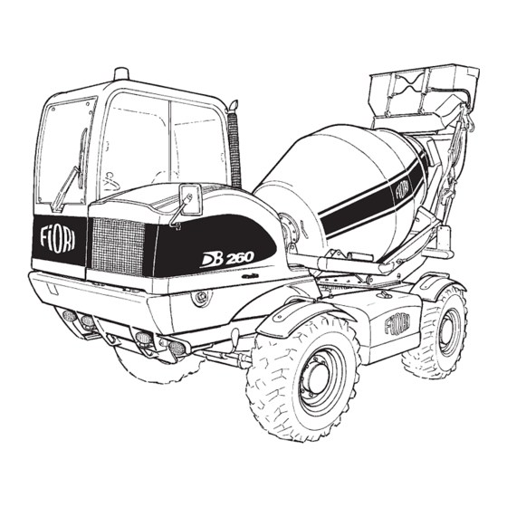
DB 260
SELF LOADING CONCRETE MIXER
USE AND MAINTENANCE MANUAL
KOHLER ENGINE Stage III B Tier 4 fi nal
RIF. 9301444206 ed. 00
FIORI GROUP S.p.A.
Via per Ferrara, 7
41034 FINALE EMILIA (Modena Italia)
Tel. +39.0535.92357 - Fax +39.0535.90960
http://www.fi origroup.com
id.:
DB 260
REV. 02
20/12/2016
Advertisement
Chapters
Table of Contents

Summary of Contents for Fiori DB 260
- Page 1 TRANSLATION FROM en_UK ORIGINAL LANGUAGE DB 260 SELF LOADING CONCRETE MIXER USE AND MAINTENANCE MANUAL KOHLER ENGINE Stage III B Tier 4 fi nal RIF. 9301444206 ed. 00 FIORI GROUP S.p.A. Via per Ferrara, 7 41034 FINALE EMILIA (Modena Italia) Tel.
- Page 3 For reasons of clarity, some illustrations in this manual show the vehicle without guards. Never use the vehicle without the guards and do not start the engine when the engine guard is open unless expressly indicated in the maintenance operations. DB 260 REV. 00 01/07/2015 id.:...
- Page 5 CONTENTS INTRODUCTION TECHNICAL FEATURES SAFETY PRECAUTIONS OPERATION AND USE MAINTENANCE OPTIONAL EQUIPMENT TECHNICAL ANNEXES DB 260 REV. 00 01/07/2015 id.:...
-
Page 7: Table Of Contents
3.1.14. CHECKS BEFORE STARTING THE VEHICLE ................30 3.1.15. STARTING THE VEHICLE ....................... 30 3.1.16. PRECAUTIONS WHILE DRIVING ....................31 3.1.17. PRECAUTIONS WHILE DRIVING IN REVERSE ................31 3.1.18. DANGEROUS WORKING CONDITIONS ..................32 DB 260 REV. 00 01/07/2015 id.:... - Page 8 OPERATION AND USE 4.0. INTRODUCTION ..........................57 4.1. REFERENCES AND DESCRIPTIONS OF THE MAIN DEVICES ..........58 4.1.1. INSTRUCTION LABELS ON THE MACHINE ................59 4.2. CONTROLS AND GAUGES ......................62 4.2.1. DRIVER’S SEAT ..........................62 DB 260 REV. 00 01/07/2015 id.:...
- Page 9 WATER FEEDING AND DISTRIBUTION CONTROLS ..............75 4.2.5. GROUND CONTROL PANEL (MIX CONTROL) ................76 4.2.6. OPERATION OF THE ELECTRONIC LITRE COUNTER AND MIX CONTROL PROGRAMMING ....................77 4.3. INSTRUCTIONS FOR USE ......................78 4.3.1. REFUELLING ........................... 78 DB 260 REV. 00 01/07/2015 id.:...
- Page 10 4.10.9.b Front unloading from chute......................104 4.10.9.c Unloading in formworks in traverse swinging mode ................105 4.10.9.d Direct unloading from hopper ......................106 4.10.9.e Concrete unloading from drum emergency door................107 4.10.10. BUCKET, DRUM AND CHUTE WASHING ..................108 DB 260 REV. 00 01/07/2015 id.:...
- Page 11 5.10.5. CHECKING AND TOPPING UP THE DRUM REDUCTION GEAR OIL LEVEL .......136 5.10.6. DRUM REDUCTION GEAR OIL CHANGE ..................136 5.10.7. REPLACING THE DRUM REDUCTION GEAR OIL .................137 5.11. ENGINE ............................138 5.11.1. CLEANING THE ENGINE AIR FILTER SEPARATOR ..............138 DB 260 REV. 00 01/07/2015 DB 260 REV. 01 05/11/2015...
- Page 12 5.13.4. CLEANING PRE-FILTER OF THE WATER PUMP ................154 OPTIONAL EQUIPMENT OPTIONAL EQUIPMENT ......................155 TECHNICAL ANNEXES ..........................165 USE AND MAINTENANCE MANUAL ENGINE PARAMETER CONTROL MONITOR ENGINE USE AND MAINTENANCE MANUAL DB 260 REV. 00 01/07/2015 DB 260 REV. 01 05/11/2015 id.:...
-
Page 13: Introduction
The Manufacturer reserves the right to make any and all modifi cations for product improvement purposes, without updating this documentation. For additional information, please feel free to contact your Dealer or the Manufacturer at your convenience. DB 260 REV. 00 01/07/2015... -
Page 14: Symbols Used In The Manual
1.4.2 WORKING PHASE (SLOW SPEED DRIVING) The driving post is turned toward the rear of the machine. Driving the machine for bucket and materials loading. Driving the machine at work sites, for approaching and manoeuvring steps to dump materials. DB 260 REV. 00 01/07/2015 id.:... -
Page 15: Intended Use
No modifi cations can be made to the machine without prior authorisation from FIORI, as they may lead to dangerous situations. It is always necessary to strictly observe the safety rules and regulations illustrated in this use and maintenance manual. -
Page 16: Driver Of The Vehicle
Prior to commencing work, the operator must check that all the safety devices are active and functioning properly: he/she is obliged to refuse to start work in the event that the requirements for safe working are not met. DB 260 REV. 00 01/07/2015... -
Page 17: Manufacturer
1.8.1 Technical Service Requests In the event of any machine failure or malfunction, it is essential to follow the instructions below: - If the trouble persists, do not try further actions or expedients. Contact the nearest authorised FIORI SERVICE CENTRE or directly: FIORI GROUP S.p.A. -
Page 18: Machine Identification
After Sales Service by means of specifi c ID numbers and letters. The following information show where the identifi cation plates and punched numbers are located, and give examples of the symbols found on the machine. DB 260 REV. 00 01/07/2015... - Page 19 The serial number is punched on the bumper side, on the right-hand side of the machine (with respect to the driving direction). CAUTION: This number must always be provided whenever requesting assistance from the FIORI After Sales Service Network. The serial number is also required to facilitate identifying the machine in the event of theft.
-
Page 20: Regulatory Provisions
- FOPS LEVEL I ISO 3449 - FOPS LEVEL II ISO 3449 (optional) QUALITY STANDARD FIORI GROUP S.p.A. is a certifi ed company: - ISO 9001 - 2008 “Quality” - ISO 14001 - 2004 “Environment” - BS OHSAS 18001 – 2007 “Safety”... -
Page 21: Declaration Of Conformity
Self loading concrete mixer Mark/Model FIORI - DB260 3, Model BF08M *BF08MB0000* Chassis number Manufacturer FIORI GROUP S.p.A. Year of manufacture 2015 is designed and manufactured in compliance with the following European Directives: Directive 2006/42/CE "Safety of machinery" Directive 2004/108/CE "Electromagnetic compatibility"... -
Page 23: Technical Features
- Front angle of attack ........................... 37° - Rear angle of attack ........................... 56° - Ground clearance under the differentials ....................370 mm - Minimum wheel radius........................1,870 mm - Minimum outside wheel radius ......................4,085 mm DB 260 REV. 00 01/07/2015 id.:... -
Page 24: Technical Data
Negative type parking brake, with internal oil-bath discs on the front axle and electro-hydraulically controlled release. STEERING Assisted by means of load-sensing power steering on 4 steering wheels; steering selection device for: 2 steer- ing wheels, 4 steering wheels - crab steering. DB 260 REV. 00 01/07/2015 DB 260 B REV. 05 01/07/2013 id.:... -
Page 25: Engine Speed Control
Closed cabin with heating system, designed in accordance with ROPS & FOPS 1st Level standards . Sliding side window 180° pivoting driving post. Anatomic seat with fl exible suspension and height adjustment, seat belts. DB 260 REV. 00 01/07/2015 id.:... - Page 26 Fuel tank in polyethylene, ........................90 litres Total hydraulic system capacity: ......................115 litres Engine oil: ............................10.35 kg WEIGHTS Operating weight: ..........................5,700 kg Max gross weight: ..........................11,700 kg load-carring capacity: .......................... 6,200 kg DB 260 REV. 00 01/07/2015 id.:...
-
Page 27: Safety Precautions
In compliance with directive 2000/14/EC the following sound power values were measured according to ISO 6394: - Sound power level measured ......................104 dB(A) - Sound power level guaranteed .......................106 dB(A) - Equivalent sound pressure level measured at the operator’s ears according to ISO 6394 ....88 dB(A) DB 260 REV. 00 01/07/2015 id.:... -
Page 28: Vibration Level
- During installation of optional components or equipment, problems may occur that put your safety at risk. Therefore, always ask FIORI for advice before installation. - FIORI is not responsible for injury, accidents or faults deriving from use of unauthorised equipment or accessories. -
Page 29: Getting On And Off The Vehicle
- After an accident, carefully inspect the protective structure, the driver’s seat, the seatbelt and all the pillars. - Replace all the parts that show any sign of damage. Original spare parts must be used as indicated in the Spare Parts Catalogue and can be ordered from FIORI. 3.1.11 ROPS (ROLL OVER PROTECTIVE STRUCTURE) - The ROPS structure serves to protect the operator and cushion the impact in the event that the vehicle overturns. -
Page 30: Fops (Falling Object Protective Structure)
- Do not try to start the engine by rolling the vehicle down a slope. - Ch eck that no one is standing within the range of action of the vehicle before starting it and using the equip- ment. - Never leave the machine with the engine on. DB 260 REV. 00 01/07/2015 id.:... -
Page 31: Precautions While Driving
- If you cannot clearly see the entire working area, ask someone to guide you with hand signals. This person must stand outside the working area and you must be able to see him or her clearly. DB 260 REV. 00 01/07/2015 id.:... -
Page 32: Dangerous Working Conditions
- Always make sure that you can clearly see the entire working or manoeuvring area. - If the cabin has windows, they must always be kept clean and intact. DB 260 REV. 00 01/07/2015 id.:... -
Page 33: Site Conditions
- Do not call out or give someone who is working a fright without good reason, and do not throw objects, not even as a joke. - Whenever you take a break, carefully check that all the controls are in NEUTRAL position and that the safety devices are locked. DB 260 REV. 00 01/07/2015 id.:... -
Page 34: Working On Slopes
- Should you make contact with an electrical line, absolutely do not leave the vehicle touching the live metal structures but wait until you have received confi rmation that the power has been cut. In addition, do not allow anyone to approach the vehicle. DB 260 REV. 00 01/07/2015... -
Page 35: Closed Environments
Hand the keys to the person in charge. Check that all the manoeuvres provided in this manual have been observed. - If you expect to work in low temperatures, check that the cooling system is fi lled with the right percentage of antifreeze. DB 260 REV. 00 01/07/2015 id.:... -
Page 36: Towing And Recovery
Securely tie the vehicle to the platform with chains or cables and block the wheels with wedges. - Ensure that the engine is off and that the windows and door (if any) are closed. DB 260 REV. 00 01/07/2015... -
Page 37: Precautions Against Residual Risks
- The conditions of the ground must be such as to allow quickly stopping the vehicle. - It is prohibited to stand underneath the working equipment. DB 260 REV. 00 01/07/2015 id.:... -
Page 38: Overturning
Make sure that the vehicle is stable and that it will not continue turning over, unfasten the seatbelt, quickly leave the vehicle trying to get off at the top to avoid being crushed by the vehicle should it continue overturning. DB 260 REV. 00 01/07/2015 id.:... -
Page 39: Tyre Bursting
Check that the cables and terminals of the electrical connections show no sign of corrosion, cracks or burns; if so, immediately contact your local FIORI dealer. In the event of an electrical fault, do not attempt to start the vehicle by running it downhill. -
Page 40: Hot And Pressurised Fluids
- Avoid inhaling or contact with the battery acids which are highly toxic and cause serious burns. - Be careful not to come into contact with cement as perspiration and other body fl uids cause an irritating alkaline reaction and in some people allergic reactions. Use protective gloves and goggles. DB 260 REV. 00 01/07/2015... -
Page 41: Fire Prevention
- Short-circuits in the electric system may cause a fi re. - Check that there are no loose or damaged parts in the system. Tighten any loose connectors or wiring terminals. If any cables or connections are corroded and/or damaged, immediately contact your local FIORI dealer. -
Page 42: Precautions During Maintenance Operations
- Signal when you are about to make a manoeuvre by voice and sounding the horn - Manoeuvre slowly - Always lock the arms or the parts that need to remain raised during the operation using external devices. DB 260 REV. 00 01/07/2015... - Page 43 - Position the vehicle on level ground, engage the parking brake and turn off the engine. - If the lubrication and greasing points require the equipment to be raised, use the special safety devices provided. IT IS DANGEROUS TO WORK UNDERNEATH THE EQUIPMENT WITHOUT THE SAFETY DEVICES. DB 260 REV. 00 01/07/2015 id.:...
- Page 44 - Unscrew the caps very slowly to release the pressure from the system before removing them completely. - Be careful during refuelling and topping up as splashes of fuel and oil may cause slipping and injury. Immediately and thoroughly clean off any soiled areas. DB 260 REV. 00 01/07/2015...
-
Page 45: Precautions During Welding Operations
Do not start the vehicle until the fault has been repaired. - No modifi cations may be made to the vehicle without prior authorisation from FIORI, as modifi cations may create risks. -
Page 46: Waste Fluid/Material Disposal
- For disposal of hazardous waste, such as oil, fuel, coolant, fi lters, batteries, and other waste materials, observe the relative laws and regulations in force. DB 260 REV. 00 01/07/2015 id.:... -
Page 47: Warning And Safety Labels (Residual Risks)
1 - Clean the labels with soap and water and dry them with a soft cloth. 2 - Replace the damaged or missing labels with original FIORI labels. 3 - If you need to replace a component bearing a safety or warning label, make sure that the new component has the same labels. - Page 48 SAFETY PRECAUTIONS VEHICLE EXTERIOR DB 260 REV. 00 01/07/2015 id.:...
-
Page 49: Meaning Of The Warning And Safety Labels
DANGER: When the vehicle is moving do not stand or allow anyone to stand in the range of action of the vehicle, especially in the arm movement areas. DB 260 REV. 00 01/07/2015 id.:... - Page 50 Using low gear on a dangerous slope: before driving on slopes with a gradient of more than about 18% engage the mechanical low gear. Shift gear when the vehicle is stationary and stable, as it is not equipped with a synchronised gearbox. DB 260 REV. 00 01/07/2015 id.:...
- Page 51 MANDATORY RULE: This symbol indicates that anti-noise protection must be used; the average exposure to noise is over 85 Lpa. Use adequate anti-noise protection in relation to your daily exposure to noise. DB 260 REV. 00 01/07/2015 id.:...
-
Page 52: Safety Devices On The Vehicle
The vehicle is automatically braked when the engine is off with the key in the “0” position. D - MECHANICAL ROTATION LOCK FOR PIVOTING DRIVING POST (fi g.1) Allows locking the driving post in the two driving positions. DB 260 REV. 00 01/07/2015... - Page 53 Designed and constructed to safeguard the operator in the event of the vehicle overturning and objects falling from heights. N - REAR VIEW MIRROR (fi g.2) The rearview mirror is essential for visibility of the rear left-hand side of the vehicle. Correctly position the mirror before starting. DB 260 REV. 00 01/07/2015 id.:...
- Page 54 Once the drum has rotated beyond 180° towards the front, the loading arms cannot be lowered. CAUTION: During front unloading, always check that the arm is raised. During front unloading never touch the arm control lever. It is advisable to engage the CONTROL LOCK (C). DB 260 REV. 00 01/07/2015...
-
Page 55: Safety Devices For Road Use
C - HAND ACCELERATOR (fi g.4) If the hand accelerator lever is not in the initial position, it is impossible to move the vehicle. D - JOYSTICK (fi g.4) Lock the joystick by inserting the locking rod D1. DB 260 REV. 00 01/07/2015 id.:... - Page 56 The unloading chute (1) must be turned crosswise and locked with the special screw pin (2). H - LOADING ARM (fi g.5) The arm (1) must be locked in a vertical position with the special steel wire (2). I - DOORS (fi g.5) Keep the doors closed while travelling. DB 260 REV. 00 01/07/2015 id.:...
-
Page 57: Operation And Use
Finally, do not rush to learn to manoeuvre the vehicle. Take your time and do things calmly and safely. CAUTION: Before starting to use or carry out maintenance on the vehicle, always read the safety regulations for the operations to be carried out as set out in Chapter 3. id.: DB 260 REV. 00 01/07/2015... -
Page 58: References And Descriptions Of The Main Devices
L - Engine assembly / hydraulic pumps M - Hydraulic oil tank N - Water system O - ROPS/ FOPS protection P - Rotary frame Q - Hydraulic bucket hatch R - Mix Control DB 260 REV. 00 01/07/2015 id.:... -
Page 59: Instruction Labels On The Machine
1 - Clean the labels with soap and water and dry them with a soft cloth. 2 - Replace the damaged or missing labels with original FIORI labels. 3 - If you need to replace a component bearing a safety or warning label, make sure that the new component has the same labels. - Page 60 The vehicle can only be moved when the lever is in the initial position (0). Indicates the three types of steering. Indicates the lever positions for chute tilting. DB 260 REV. 00 01/07/2015 id.:...
- Page 61 It stands for the exact position of the intake fi lter above the inlet joint, when the suction pipe is placed on the rotating framework to prevent it from breaking during the rotation of the same framework. id.: DB 260 REV. 00 01/07/2015...
-
Page 62: Controls And Gauges
This chapter provides all the useful information you need to quickly get to know and safely use the vehicle controls. The legend below divides this information into well-defi ned groups: - Driver’s seat - Driving post instrument panel - Operating control panel 4.2.1. DRIVER’S SEAT DB 260 REV. 00 01/07/2015 id.:... -
Page 63: Height- And Depth-Djustable Driver's Seat With Seatbelt
(see the procedure described in Chapter 4.3.9). It is prohibited to use CRAB STEERING if the driving post is facing the drum. In this position steering is inverted with respect to steering wheel rotation. id.: DB 260 REV. 00 01/07/2015... -
Page 64: G (Mechanical) Gearshift Control Lever
4.2.1 n - N - Windscreen water switch (fi g. 2). Allows you to pump the windscreen washer fl uid. 4.2.1.o - O - Rotating light switch (fi g. 2). Snap switch to turn on the rotating beacon on the cabin roof. DB 260 REV. 00 01/07/2015 id.:... -
Page 65: Short Manual
4.2.1.u - U - Fuses and Relays (fi g. 3). The fuses and relays are positioned inside the driving post. Using the key provided, open the door to access the fuses and the relays. id.: DB 260 REV. 00 01/07/2015... -
Page 66: Electronic Engine Parameter Control Monitor
(par. 4.2.2.l-H) together with the red LED. CAUTION: Refer to the user manual for further information about the instrument’s functions; the user manual is supplied separately from this document. Where necessary, ask an Authorised FIORI Service Centre for assistance. DB 260 REV. 00 01/07/2015 id.:... -
Page 67: Driving Post Instrument Panel
9 - Yellow warning light: indicates an engine fault, the amber led on the monitor also lights up. 10 - Yellow warning light: indicates that there is water in the fuel sediment bowl. 11 - Red warning light: indicates that the hydraulic oil fi lter is clogged. id.: DB 260 REV. 00 01/07/2015... -
Page 68: Water Liter Counter
17 -Display: displays the hours of operation, fuel level and litre counter. Note: if the FIORI BATCH CONTROLLER is installed on the machine, all functions of the litre counter located on the electronic dashboard are not active, as the functions are displayed on the operating panel. -
Page 69: Maintenance Schedule
In case the warning light (1) stays on, it means that it is almost time to do maintenance to the machine (the warning light indicates this event about 20 hours before the deadline set by FIORI). The preset service interval is every 500 hours. Therefore, the warning light will fl ash after 500, 1000, 1500, 2000, ... -
Page 70: Drum Rotation Switch
MIX CONTROL (see chapter 4.2.6). Note: if the FIORI BATCH CONTROLLER is installed on the machine, all functions of the litre counter located on the electronic dashboard are not active, as the functions are displayed on the operating panel. -
Page 71: Engine Starter And Stopping Switch
When the ignition key is released from the positions 2 and 3 it automatically returns to this position. 2 Position not activated 3 Starting position Activates the starter motor that turns the engine. As soon as the engine starts, the engine rpm is displayed on the parameter control monitor. id.: DB 260 REV. 00 01/07/2015... -
Page 72: Rotary Switch With Horn Push Button Direction Indicators Toggle Switch
The lights come on only if the ignition key is inserted - Position lights: turn the rotary switch (3) forward by one click - Low beams: turn the rotary switch (3) forward by 2 clicks. DB 260 REV. 00 01/07/2015 id.:... -
Page 73: Operating Control Panel
4.2.3 b - B - Drum raising lever (fi g. 9). The lever controls drum raising. Follow the instructions below: Position 1 - Drum raising. Position N - Neutral. Position 2 - Drum lowering. id.: DB 260 REV. 00 01/07/2015... -
Page 74: Unloading Chute Control Lever
Position “3” - Downward loader rotation. Press button F to close the hydraulic loader hatch. Position “4” - Upward loader rotation. Press button F to open the hydraulic loader hatch. Position “N” - Neutral. DB 260 REV. 00 01/07/2015 id.:... -
Page 75: Water Feeding And Distribution Controls
Used to wash the bucket, drum and chute and is positioned at the rear of the vehicle. To be connected to the union H of the switching valve B turning the lever to position 2. id.: DB 260 REV. 00 01/07/2015... -
Page 76: Ground Control Panel (Mix Control)
CAUTION: Before approaching the MIX CONTROL warn the operator in the cabin of your presence. Collaboration and eye contact between the various operators around the vehicle is essential for your own and others’ safety. DB 260 REV. 00 01/07/2015 id.:... -
Page 77: Operation Of The Electronic Litre Counter And Mix Control Programming
OPERATION AND USE 4.2.6 OPERATION OF THE ELECTRONIC LITRE COUNTER AND MIX CONTROL PROGRAMMING Note: if the FIORI BATCH CONTROLLER is installed on the machine, value 0000 must be set to dis- able the MIX CONTROL programming. - The litre counter indicates the litres of water pumped into the mixing drum. -
Page 78: Instructions For Use
Before checking or fi lling the fuel tank, make sure that there are no open fl ames or smoking materials in the area. Do not refuel with the engine on. Do not use matches, lighters or torches as light source. DB 260 REV. 00 01/07/2015... -
Page 79: Level Check
Check that it contains water through the suction pipe union A. If there is no water, refi t the pre-fi lter D, fi ll the pump body with water through the suction union A holding the id.: DB 260 REV. 00 01/07/2015... -
Page 80: Adjusting The Seat
CAUTION: Operation to be carried out before starting the vehicle. To adjust the fi eld of vision of the sideview mirror (1), turn it so that you can see the rear left-hand side of the vehicle as shown in the fi gure. DB 260 REV. 00 01/07/2015... -
Page 81: Driving Post Pivoting
Press the lever (1) to release the driving post, turn it in the desired direction and relock the lever (1). If the driving post is not perfectly locked, dedicated microswitches (2) will not allow vehicle movement. id.: DB 260 REV. 00 01/07/2015... -
Page 82: Starting The Engine
When the engine has started, let it run at about 1000 rpm for a few minutes to allow the oil to warm up and lubricate all the parts; this is essential in cold climates. DB 260 REV. 00 01/07/2015... -
Page 83: Engine Operation At Low Rpm
To disengage it, turn the button (1) and release it. For temporary stops on slopes or where necessary engage the parking brake by pressing the button (1). To release the brake in the event of a braking system failure, see chapter 4.5.1. id.: DB 260 REV. 00 01/07/2015... -
Page 84: Starting And Driving The Vehicle
- Check that you can safely move forward, then start depressing the accelerator pedal (D) to move the vehicle. DANGER: Steer maintaining an adequate speed and act gradually on the steering wheel, especially when you are on a slope. DB 260 REV. 00 01/07/2015 id.:... -
Page 85: Field Of Indirect Visibility Of The Rear Of The Vehicle
This allows you to safely reverse from and approach the unloading area. CAUTION: For the display (2) operation, refer to its user manual that comes with the vehicle. DANGER: Check that the display (2) is properly set for direct visibility (NO MIRROR). id.: DB 260 REV. 00 01/07/2015... -
Page 86: Stopping The Vehicle
Use the handles and steps to get off the vehicle. If you leave the vehicle, close and lock all the windows and the door (if present). Check that the fuel tank cap and the engine compartment lid are locked. DB 260 REV. 00 01/07/2015 id.:... -
Page 87: Transporting The Vehicle
- Check that the lid or other moving parts are properly closed. - Measure the maximum height of the vehicle from the ground. Inform the driver of the transport vehicle of the overall height before he sets off. id.: DB 260 REV. 00 01/07/2015... -
Page 88: Lifting The Vehicle With A Crane
- Hook the chains onto the special hooks. DANGER: During lifting, stand well away from the vehicle and do not stand under the load. Sudden movements or the chains snapping may cause injury and even death. DB 260 REV. 00 01/07/2015 id.:... -
Page 89: Towing And Recovery
- Use a towing vehicle with a towing capacity of more than 11,700 kg with full load and 5,700 kg when unladen. - When you have fi nished the towing operations, restore the negative brake (Chapter 4.5.1). id.: DB 260 REV. 00 01/07/2015... -
Page 90: Releasing The Parking Brake In The Event Of A Brake Supply System Fault
- Tighten the four screws (1) of the axles using a no. 14 wrench tightening them by one turn each one after another in sequence until they are at the end of travel mechanically releasing the brake. - To resume the brake original conditions, follow the above procedures in reverse order. DB 260 REV. 00 01/07/2015... -
Page 91: Driving On Public Roads
CAUTION: The vehicle may circulate on the road with a full load and empty according to the carrying capacity indicated on the homologation plate. CAUTION: At regular intervals, check proper functioning of the lights and immediately replace any blown bulbs. id.: DB 260 REV. 00 01/07/2015... -
Page 92: Homologation For Road Use (Italy)
- After refi lling/topping-up, run the engine for a few minutes to allow the water and antifreeze to mix well. CAUTION: To use the vehicle at low temperatures, you also need to change the lubricants and use types with an appropriate viscosity (see the RECOMMENDED LUBRICANTS AND FLUIDS TABLE). DB 260 REV. 00 01/07/2015 id.:... -
Page 93: Summer/Winter Heating System
Slacken off nut A, unscrew nut B and rotate scale C; cock D is located on the chassis under the cab, turn the lever 90° CW to close the circuit. During the winter, or when temperatures are low, open the circuit by turning the valve lever 90° CCW. id.: DB 260 REV. 00 01/07/2015... -
Page 94: Precautions In The Event Of Long Periods Of Inactivity
- Do not leave biodesel (where used) inside the engine supply circuit. - To keep the engine lubricated, let it run for at least 20 minutes no less than once a week. CAUTION: For more information, contact an AUTHORISED FIORI WORKSHOP. 4.10 WORKING PHASES CAUTION: Before proceeding, always read the safety regulations for the operations to be carried out as set out in Chapter 3. -
Page 95: Correct Use Of The Vehicle
- Always check the working area for snow, small landslips, gravel and tilled soil which may suddenly change the working conditions and vehicle stability. Maximum surmountable gradient when loaded (ramps, obstacles, jerking)........23° (41.6%) Maximum permissible gradient on steep roads during transfer: front ..............................14° (25%) Side ..............................4.6° (8%) id.: DB 260 REV. 00 01/07/2015... - Page 96 - If the fuel reserve warning light comes on while you are working on a slope, immediately refuel; given that the vehicle is inclined, the engine may take in air and stall unexpectedly, posing a grave danger to your safety. DB 260 REV. 00 01/07/2015 id.:...
-
Page 97: Concrete Composition And Batching Table
AGGREGATE WATER CEMENT SAND m GRAVEL m 0,80 0,40 STANDARD FOR FOUNDATIONS 0,80 0,40 0,80 0,40 (A) FOR OPERATIONS WITH 0,80 0,40 FORMWORKS 0,80 0,40 0,80 0,40 (A) REINFORCED CONCRETE, IRON EXCLUDED 0,80 0,40 id.: DB 260 REV. 00 01/07/2015... -
Page 98: First Filling With Mixing Water
- Wait until the tank is full (when water starts fl owing from the water inlet pipe and from the tank). - Stop the transfer pump and close the cover L. CAUTION: The pump automatically stops when the water tanks are full. DB 260 REV. 00 01/07/2015... -
Page 99: First Fi Lling With Mixing Water
- Check the quantity of water pumped in on the litre counter, which in this fi rst phase should be 80-90% of the total quantity. - Refer to the CONCRETE COMPOSITION AND BATCHING table, chapter 4.10.4, to calculate the optimal quantity of water. id.: DB 260 REV. 00 01/07/2015... -
Page 100: Cement Loading
- Raise the arm to its maximum height. - Open the unloading hatch and wait until the cement has poured into the drum through the hopper, helping it along by vigorously shaking the bucket with the arm. DB 260 REV. 00 01/07/2015... -
Page 101: Cement In Silos
- On the mechanical gearbox, select the 1st working speed (low). - Dig into the heap with the bucket and at the same time raise the arm, that way fi lling the bucket with a larger id.: DB 260 REV. 00 01/07/2015... -
Page 102: Mixing And Second Filling With Water
- Keep the drum rotating for about 2 minutes after the last aggregate loading phase. - Add the remaining amount of water, about 30% of the total, following the procedures described in chapter 4.10.5 to obtain the desired fl uidity. DB 260 REV. 00 01/07/2015... -
Page 103: Concrete Unloading
fl uidity of the concrete. - Raise the drum but not necessarily to its maximum height. - Visually inspect regular concrete unloading. id.: DB 260 REV. 00 01/07/2015... -
Page 104: Front Unloading From Chute
4.10.9.b Front unloading from chute (fi g. 38) CAUTION: During front unloading, never lower the loader arm. The new version of the FIORI concrete mixer allows front unloading from the left-hand side, directly visible by the operator in the cabin. -
Page 105: Unloading In Formworks In Traverse Swinging Mode
fl uidity of the concrete. - Visually inspect regular concrete unloading. - Drive slowly in the working direction, avoiding sudden braking or acceleration. id.: DB 260 REV. 00 01/07/2015... -
Page 106: Direct Unloading From Hopper
- Adjust the drum rotation speed. The concrete unloading speed depends on the engine speed, the drum rotation speed, the height to which the drum is raised and the fl uidity of the concrete. DB 260 REV. 00 01/07/2015... -
Page 107: Concrete Unloading From Drum Emergency Door
- Revert the drum rotation direction to mixing (clockwise). - Approach and position in the new unloading area and follow all the instructions given above. 4.10.9.e Concrete unloading from drum emergency door DANGER: This operation must be performed by Authorised FIORI Workshops qualifi ed personnel. id.: DB 260 REV. -
Page 108: Bucket, Drum And Chute Washing
- Change drum rotation from clockwise to anticlockwise. - Drain out all the water in the drum and wash the chute and the extensions. - Remove the extensions. - Lower the bucket and wash it inside and out. DB 260 REV. 00 01/07/2015 id.:... -
Page 109: Internal Cleaning Of The Mixing Drum
Having to work inside the drum to solve these problems, it is obligatory to go to an equipped workshop and dismantle the drum from the vehicle so that these operations can be carried out on the ground in safe conditions. id.: DB 260 REV. 00 01/07/2015... -
Page 111: Maintenance
MAINTENANCE 5.1 FOREWORD This manual provides all the information necessary for routine maintenance on the FIORI vehicles. This chapter addresses the persons that will physically be carrying out routine maintenance and provides the rules to follow to achieve the end result, namely, repair when necessary and help ensure functionality of the FIORI vehicle over time. -
Page 112: Visual External Inspection
5.1.2 CLEANING THE VEHICLE Clean the vehicle with water. Pay particular attention to the bottom of the vehicle. Do not let mud to deposit under the engine and the transmission. Check that the radiator grille is not clogged. DB 260 REV. 00 01/07/2015... -
Page 113: Checking For Damages
2 - no.1 double fork wrench 17 - 19 3 - no.1 double fork wrench 24 - 27 4 - no.1 oil fi lter wrench 5 - no.1 M18 T-wrench 6 - no.1 fl at-blade/cross-slotted screwdriver 7 - no.1 manual grease pump id.: DB 260 REV. 00 01/07/2015... -
Page 114: Routine Maintenance And Checks
- Engine oil cap, level gauge and fi lter - Engine accelerator cables - Starter motor and alternator - Hydraulic oil tank cap - Radiator - Engine air fi lter - Hydraulic oil fi lter. DB 260 REV. 00 01/07/2015 id.:... -
Page 115: Maintenance Schedule
- Hydraulic oil fi lter replacement - Air, oil and diesel fi lter replacement CAUTION: The instructions for engine maintenance and running-in are given by way of example. Follow the instructions given in the engine manufacturer’s instruction manual. id.: DB 260 REV. 00 01/07/2015... -
Page 116: Scheduled Maintenance Table
BRAKING SYSTEM TANK CAP BLEEDER NEGATIVE PARKING BRAKE PARKING BRAKE TEST BRAKING SYSTEM FLUID OPERATION OF THE HYRAULIC SERVICE DEVICES HYDRAULIC SYSTEM OIL HOSE RUBBING AND DAMAGE HYDRAULIC OIL TANK CAP BLEEDER HYDRAULIC OIL FILTER DB 260 REV. 00 01/07/2015 id.:... -
Page 117: Engine Maintenance Schedule
PRE-FILTER WATER TRANSFER PUMP 5.5 ENGINE MAINTENANCE SCHEDULE CAUTION: For maintenance, refer to the table on page 22 of the engine user manual, enclosed with this document. EVERY WORKING AREA 8000 HOURS DIESEL OXIDATION CATALYST (DOC) id.: DB 260 REV. 00 01/07/2015... -
Page 118: Recommended Lubricants And Fluids Table
Satisfactory engine performance is dependent on the use of a good quality fuel. The use of a good quality fuel will give the following results: long engine life and acceptable exhaust emissions levels . The fuel must meet the minimum requirements that are stated in the table. DB 260 DB 260 REV. 00 REV. - Page 119 0,05% maximum D473 D473 Gums and Resins mg/100mL 10 mg per 100 mL D381 ISO6246 maximum Lubricity corrected wear 0,52 maximum D6079 ISO12156-1 scar diameter at 60 °C (140 °F). DB 260 REV. 01 05/11/2015 id.: DB 260 REV. 00 01/07/2015...
- Page 120 BS 2869: 2010 CLASS A2 or EU equivalent “EU Off Road Diesel fuel. Acceptable from 2011 MUST have less than 10 PPM sulfur level” All the fuels must comply with the specifi cation in the table Specifi cation Distillate Diesel Fuel. DB 260 REV. 00 01/07/2015 id.: DB 260 REV.
-
Page 121: General Inspections
PIVOTING DRIVING POST AXLE HUBS TRANSMISSION SHAFT OSCILLATING CHASSIS MIXER ROTATION SAFETY STOP DEVICE DRUM LIFTING CYLINDERS ARM LIFTING CYLINDERS LOADER CONNECTING ROD AND TIE-ROD LOADER CYLINDERS MIXER ROLLERS UNLOADING CHUTE LIFTING ARM MIXER ROTATION FIFTHWHEEL id.: DB 260 REV. 00 01/07/2015... -
Page 122: Cleaning And Draining The Fuel Tank
- Turn the engine off, take the ignition key out and make certain the parking brake is on. - Lubricate pinion C with grease using a hard bristle brush. - Grease the internal rack B with the nipples. DB 260 REV. 00 01/07/2015... -
Page 123: Scraper Blade And Loading Bucket Hatch Bellows
- Check the wear and tear of the scraper blade A on the loading bucket and replace it if damaged. - Check that bellows B protecting the cylinder rods are in proper working order and replace them if damaged. id.: DB 260 REV. 00 01/07/2015... -
Page 124: Axle And Wheels
- If oil trickles from the level gauge caps (4) - (5) - (6), it is not necessary to top up; if not, top up using a funnel adding oil through the fi ller cap (2) - (3) and the level gauge cap (6) until reaching the optimal level. - Screw all the caps back on after topping up. DB 260 REV. 00 01/07/2015... -
Page 125: Replacing The Oil In The Front And Rear Axles
- Unscrew the fi ller cap (6) and (7). - Using a funnel, add the required type of oil through the fi ller cap (6) and (7) until oil trickles from the hole in the level gauges (4) and (5). id.: DB 260 REV. 00 01/07/2015... -
Page 126: Checking And Adjusting The Tyre Presure
Make sure that the fl exible air hose is properly connected to the tyre valve. CAUTION: Check and tighten the rim bolts before each work shift, alternately going from one bolt to the one diametrically opposite in the order shown in the fi gure. DB 260 REV. 00 01/07/2015... -
Page 127: Replacing The Wheels
It is prohibited to change a tyre on a slope or near canals or ditches to prevent the vehicle from overturning and causing serious injury. This operation must be performed on a solid, fl at surface. id.: DB 260 REV. 00 01/07/2015... - Page 128 fi t an adapter (fork) in the jack. Slowly jack up the vehicle until the arch rests on the chassis, then continue jacking up slowly until the defl ated tyre lifts off the ground and then proceed with repairing it. DB 260 REV. 00 01/07/2015...
- Page 129 If you want to invert a wheel, operate as shown in the fi gure; you cannot interchange the tyres crosswise, because of the type of tread. Fit the wheels with the tyre tread facing in the direction shown in the fi gure. id.: DB 260 REV. 00 01/07/2015...
-
Page 130: Brakes
FLUIDS TABLE; using unsuitable fl uids will damage the braking system. Regularly check good functioning of all the braking components. CAUTION: In the event of malfunctioning, immediately contact the nearest AUTHORISED FIORI WORKSHOP. The brake fl uid tank is installed to the side of the revolving driving post. -
Page 131: Replacing The Braking System Fluid
- Unscrew the bleeder A by half a turn and have your colleague depress the brake pedal until bubble-free fl uid fl ows from the bleeder. - Repeat the operation on all the axle bleeders A. - Regularly top up the brake fl uid tank. id.: DB 260 REV. 00 01/07/2015... -
Page 132: Efficiency Of The Hand Brake
- Ensure that the parking brake button (1) is fully pressed down. - If you notice that the vehicle moves, contact an AUTHORISED FIORI SERVICE CENTRE. CAUTION: Do not use the vehicle if the parking brake is not fully effi cient. -
Page 133: Hydraulic System
- The bleeder cap A is disposable and hence does not need to be cleaned. - Replace it only if broken or clogged with an identical one in order to keep the system adequately pressurised. id.: DB 260 REV. 00 01/07/2015... -
Page 134: Change The Hydraulic Oil Filter Cartridge
fi ller cap A back on. - It is essential to keep a stock of spare cartridges D, which can be ordered from the AUTHORISED FIORI SERVICE CENTRES or directly from FIORI SPARE PARTS DEPARTMENT. -
Page 135: Replacing The Hydraulic Oil
Once started, keep it at idle speed for a few minutes before checking proper operation of the hydraulic functions. - Bleed any air that may have formed in the system by loosening the bleeder pipe E. id.: DB 260 REV. 00 01/07/2015... -
Page 136: Checking And Topping Up The Drum Reduction Gear Oil Level
- Screw the level gauge cap back on and then turn the drum so that the level gauge hole A is in horizontal position and the fi ller cap hole B positioned at the top. - Fill with the recommended oil using a syringe. - Screw the fi ller cap B back on. DB 260 REV. 00 01/07/2015 id.:... -
Page 137: Replacing The Drum Reduction Gear Oil
- Unscrew the drain cap A and drain out all the oil into a prearranged container. - Add the specifi ed oil through the fi ller cap B using a syringe. - Screw the caps A and B back on. id.: DB 260 REV. 00 01/07/2015... -
Page 138: Engine
Limit the pressure to 2 bar according to the regulations in force. - Move the vehicle onto fl at ground, engage the parking brake, turn off the engine and remove the ignition key. DB 260 REV. 00 01/07/2015 id.:... -
Page 139: Checking And Topping Up The Coolant Level
- It is essential to keep a stock of spare cartridges B and C, which can be ordered from the AUTHORISED FIORI SERVICE CENTRES or directly from FIORI SPARE PARTS DEPARTMENT. 5.11.3 CHECKING AND TOPPING UP THE COOLANT LEVEL (fi g. 25) CAUTION: Use only coolant of the type and brand recommended by the manufacturer, as indicated in the Recommended Lubricants and Fluids table in the right WATER/ANTIFREEZE percentages. -
Page 140: Replacing The Engine Coolant
- Close the engine compartment lid. - Start the engine and let it run for a few minutes. - Let the engine cool down. - Check the fl uid level in the tank B and top up if necessary. DB 260 REV. 00 01/07/2015 id.:... -
Page 141: Checking And Adjusting The Alternator Belt Tensioning
Open the lid only with the engine off. CAUTION: If you have any doubts about the operating procedures, also refer to the instruction manual provided separately from this manual. Where necessary, ask an AUTHORISED FIORI SERVICE CENTRE or WORKSHOP for assistance. -
Page 142: Air Bleeding In The Engine Fuel Supply System
- For the operations to be carried out, refer to the engine manufacturer’s manual attached. - It is essential to keep a stock of spare fi lters, which can be ordered from the AUTHORISED FIORI SERVICE CENTRES or directly from FIORI SPARE PARTS DEPARTMENT. -
Page 143: Checking And Topping Up The Engine Oil Level
Open the lid only with the engine off. CAUTION: If you have any doubts about the operating procedures, also refer to the instruction manual provided separately from this manual. Where necessary, ask an AUTHORISED FIORI SERVICE CENTRE or WORKSHOP for assistance. -
Page 144: Replacing The Engine Oil Filter
- For the operations to be carried out, refer to the engine manufacturer’s manual attached. - It is essential to keep a stock of spare fi lters, which can be ordered from the AUTHORISED FIORI SERVICE CENTRES or directly from FIORI SPARE PARTS DEPARTMENT. -
Page 145: Engine Diagnostics
MAINTENANCE 5.11.12 ENGINE DIAGNOSTICS (fi g. 29) CAUTION: Engine diagnostics must be run by an authorised FIORI technician. - Move the vehicle onto fl at ground, engage the parking brake. - Remove the LH ABS cover A on the dashboard panel, and insert the diagnostics connector into its socket B. -
Page 146: Electric Components
COLOR POS. AMPERAGGIO COLOR blue 7,5A brown 7,5A brown blue violet beige violet blue blue 7,5A brown blue blue blue blue beige beige beige beige violet violet 7,5A brown DB 260 DB 260 REV. 02 REV. 00 01/07/2015 20/12/2016 id.:... - Page 147 20 - (F120) – Relay power supply (K110). 21 - (SPARE 1) - Spare fuse. 22 - (SPARE 2) - Spare fuse. 23 - (SPARE 3) - Spare fuse. 24 - EGR power. 25 - Diagnostics socket. id.: DB 260 REV. 00 01/07/2015...
- Page 148 04 - K104 - Micro-relais de validation démarrage avec commande au point mort. 05 - K105 - Micro-relais de validation avancement. 06 - K106 - Micro-relais a disposition. 07 - K107 - Micro-relais de coupure moteur. DB 260 DB 260 REV. 02 REV. 00...
-
Page 149: Electronic Dashboard Warning Lights
5.12.2 ELECTRONIC DASHBOARD WARNING LIGHTS (fi g. 35) In the event of malfunctioning of the electronic panel, contact the nearest AUTHORISED FIORI SERVICE CENTRE or FIORI SPARE PARTS DEPARTMENT directly. In the event of replacement, the panel is delivered already programmed. -
Page 150: Replacing The Light Bulbs
D - number plate light bulb ...................... 12V - W5W E - rotating beacon bulb ......................12V - 55W H1 F - courtesy light bulb ......................12V - C5W G - working light bulb ....................... 12V - 886 50W DB 260 REV. 00 01/07/2015 id.:... -
Page 151: Checking And Topping Up The Battery Electrolyte Level
- Regularly check that the cable terminals are properly secured and lubricated with Vaseline. - Always keep the top of the battery clean. - Before working on the terminals, disconnect the end on the earth cable. id.: DB 260 REV. 00 01/07/2015... -
Page 152: Battery Pins Contact
- Unscrew the retaining clip. - Remove the battery from its seat and replace it. - Refi t the battery following the removal operations in reverse order, and remember to grease the terminals with Vaseline grease. DB 260 REV. 00 01/07/2015 id.:... -
Page 153: Water System
- Check by means of the fl ow meter C that the water fl ow rate is higher than 250 litres/min. - Also check for leaks from the valve unions B and from the suction pipe unions A and H. - Check that the suction fi lter F is in proper working order. id.: DB 260 REV. 00 01/07/2015... -
Page 154: Water Pump Emergency Activation
Finally, reposition it inside the fi ller neck and refi t the closing cap C. CAUTION: Check that there is water inside th pump (see chapter 4.3.3 for the related procedure). DB 260 REV. 00 01/07/2015... -
Page 155: 6 Optional Equipment
6.3.1. 6.3.1. OPERATION OPERATION ....................................................162 6.3.2. 6.3.2. MAINTENANCE MAINTENANCE ..................................................163 6.3.3. 6.3.3. TECHNICAL DATA ................................................164 6.3.4. 6.3.4. SCHEDULED MAINTENANCE TABLE ....................................164 DB 260 REV. 00 02/07/2015 DB 260 REV. 01 05/11/2015 id.:... -
Page 156: Drum Closing Hatch Drum Closing Hatch
Do not climb on the machine, do not place your limbs or parts of your body in the drum opening: risk of crushing if the hatch is closed inadvertently! Do not use the arms as lifting device. DB 260 REV. 00 02/07/2015... -
Page 157: Power Jet Cleaner
Indicates that the water fi lter of the power jet cleaner system must periodically be cleaned. Indicates the positions of the lever for use of the power jet cleaner or the water suction pump. DB 260 REV. 00 02/07/2015 id.:... -
Page 158: References And Descriptions Of The Main Devices
Turn switch lever E to position “2” to trigger the switch that enables water sensor L. If the sensor detects that there is no water fl ow due to the empty tank, pump H automatically stops. DB 260 REV. 00 02/07/2015 id.:... -
Page 159: Using The Power Jet Cleaner
- When you have fi nished work, fully open the low-pressure nozzle B of the power jet cleaner. - Turn the lever of the switch E to position (1) to close the oil inlet to the pump H. DB 260 REV. 00 02/07/2015 id.:... -
Page 160: Precautions For Use In Cold Climate Conditions
CAUTION: Use only nozzles with a fan-pattern jet to clean delicate surfaces, holding the nozzle 75cm away from the surface to be cleaned. CAUTION: In the event of malfunctioning, immediately contact the nearest AUTHORISED FIORI WORKSHOP. 6.2.5. PRECAUTIONS FOR USE IN COLD CLIMATE CONDITIONS If you have to work in ambient temperatures close to 0°C, the pump has to be operated without pressure for... -
Page 161: Cleaning Or Replacing The Filter Cartridge
- Refi t the cartridge and make sure that it is properly in place. - Close the cover A. - It is essential to keep a stock of spare cartridges B, which can be ordered from the AUTHORISED FIORI SERVICE CENTRES or directly from FIORI SPARE PARTS DEPARTMENT. -
Page 162: Air-Conditioner Air-Conditioner
- Start the engine. - Adjust the fan speed as desired using the knob on the switch A. Note: the air conditioner is only activated if the fan speed is set at least to the fi rst level. DB 260 REV. 00 02/07/2015... -
Page 163: Maintenance Maintenance
- If the machine is parked in the sun for long periods of time, move the fan control (switch A and the thermostat B) to the highest level; aerate the cabin thoroughly, driving for several minutes with the windows open. - Should the system performance decrease, please contact an Authorised FIORI Service Centre or Workshop to check the quantity of refrigerant. -
Page 164: Technical Data
= Check and repair = Replace = Clean = Grease or lubricate REGULAR MAINTENANCE INTERVALS WORKING AREA EVERY EVERY EVERY EVERY 250 HOURS 500 HOURS 1200 HOURS 2000 HOURS AIR-CONDITIONER GAS AIR-CONDITIONER GAS FILTER DB 260 REV. 00 02/07/2015 id.:... -
Page 165: Technical Annexes
TECHNICAL ANNEXES CAUTION For a better consultation you can ask for the vehicle’s wiring - hydraulic diagrams in PDF format at the FIORI email address: info@fi origroup.com id.: DB 260 REV. 00 01/07/2015... - Page 166 TECHNICAL ANNEXES HYDRAULIC DIAGRAM DB 260 REV. 00 01/07/2015 id.:...
- Page 167 CHECK VALVE STEERING SELECTION DISTRIBUTOR FLOW INVERTER HYDRAULIC STEERING PRIORITY VALVE RETURN OIL COLLECTION BLOCK HEAT EXCHANGER HYDROSTATIC TRACTION MOTOR DRUM ROTATION MOTOR DRUM ROTATION PUMP HYDROSTATIC TRACTION PUMP HEAT ENGINE DOUBLE PUMP PRESSURISED FILTER id.: DB 260 REV. 00 01/07/2015...
- Page 169 Air fi lter differential pressure sensor signal too high Air fi lter differential pressure sensor signal too low Atmosphere pressure sensor signal too high Atmosphere pressure sensor signal too low Atmosphere pressure sensor signal too high Atmosphere pressure sensor signal too low id.: DB 260 REV. 00 01/07/2015...
- Page 170 Fuel temperature (w/pump) sensor signal too low Crank position (CKP) sensor no pulse Crank position (CKP) sensor performance invalid Camshaft position (CMP) sensor no pulse Camshaft position (CMP) sensor performance invalid Crank position e camshaft position sensor no pulse DB 260 REV. 00 01/07/2015 id.:...
- Page 171 Engine overrun Crank position and camshaft position sensor no pulse Engine over speed condition Crankshaft and Camshaft synchronous error Crank position (CKP) sensor no pulse Crank position (CKP) sensor performance invalid Starter switch short to BATT Starter switch short to BATT Starter relay short to battery Starter relay short to GND Clutch switch circuit malfunction (manual transmission only)
- Page 172 “COM1 Injector drive system output short to BATT Injector1 or Injector3 (4cyl engine)/Injector2 (3cyl engine) output short to BATT “ 1397 “COM1 Injector drive system output short to GND Injector1 or Injector3 (4cyl engine)/Injector2 (3cyl engine) output short to GND “ 1397 COM1 Injector drive system output open load both Injector1 and Injector4 (4cyl engine)/Injector2 (3cyl engine) open load...
- Page 173 Battery 5V reference 2 circuit high (5V power supply for sensor) 3510 Battery 5V reference 2 circuit low (5V power supply for sensor) 3510 Electric lift pump relay short to battery 4082 Electric lift pump relay short to GND 4082 Fuel fi...
- Page 175 PowerView Model PV101-C User’s Guide Version 3.2 2013-04-08 00-02-0796 Catalog Section 78...
- Page 177 Table of Contents Introduction ................1 Engine and Transmission Parameters ..............2 Faceplate Features ....................3 Navigation and Keypad Functions ................4 First Time Start Up ..............8 Main Menu Options ..............11 Go to 1-Up Display/Go to 4-Up Display ..............11 DPF Regen* ......................
- Page 178 OEM Menu ................27 MODBUS Setup ....................27 CANBUS Data Rate ....................28 Select Engine ECU ....................29 Set Source Address ....................30 Restore All Defaults ....................30 Clear Machine Hours .................... 30 Set Machine Hours ....................30 Fuel Setpoints ....................... 31 DPF Regen Menu ON/OFF ...................
- Page 179 In order to consistently bring you the highest quality, full featured products, we reserve the right to change our specifications and designs at any time. The latest version of this manual can be found at www.fwmurphy.com. Warranty - A limited warranty on materials and workmanship is given with this Enovation Controls product.
- Page 180 BEFORE BEGINNING INSTALLATION OF THIS MURPHY PRODUCT: Disconnect all electrical power to the machine. Make sure the machine cannot operate during installation. Follow all safety warnings of the machine manufacturer. Read and follow all installation instructions.
-
Page 181: Introduction
Introduction Congratulations on purchasing your PowerView display, a multifunction tool that provides a window into the many parameters and service codes of modern electronic engines and transmissions. This guide is intended to help you set up your PowerView display and identify navigation basics and product features. The display’s simple navigation and powerful features allow you to quickly master the product. -
Page 182: Engine And Transmission Parameters
Engine and Transmission Parameters The following are some of the engine and transmission parameters which can be displayed in standard or metric units as well as in English, Spanish, French, Italian or German languages (when applicable, consult engine or transmission manufacturer for SAE J1939 supported parameters): Engine RPM Transmission oil... -
Page 183: Faceplate Features
Faceplate Features 00-02-0796 - 3 - 2013-04-08... -
Page 184: Navigation And Keypad Functions
Navigation and Keypad Functions The keypad on the PowerView display is a capacitive touch sensing system. There are no mechanical switches to wear or stick. The keys on the keypad perform the following functions: Menu – Enter or exit menu screens. Left Arrow –... -
Page 185: Basic Navigation
Basic Navigation 1. When Menu is pressed, the Main menu items display. 2. Press the Arrow Keys to move the selection bar to other menu items. 00-02-0796 - 5 - 2013-04-08... - Page 186 3. Certain menus have multiple pages. Scrolling to the top or bottom item on the current page reveals other menu items on additional pages. 00-02-0796 - 6 - 2013-04-08...
- Page 187 When the desired item is highlighted by the cursor, pressing Enter selects that item and displays the corresponding screen. 00-02-0796 - 7 - 2013-04-08...
-
Page 188: First Time Start Up
First Time Start Up When power is first applied to the display, the Murphy logo is displayed. NOTE: Expect a 20-minute warm up for the display at temperatures of C/-20 00-02-0796 - 8 - 2013-04-08... - Page 189 If the Engine ECU is broadcasting a ‘Wait to Start' message, this screen will be shown. Engine manufacturers typically recommend against starting the engine while this message is broadcasted from the ECU. Once the ECU stops broadcasting this message, this screen will no longer be displayed. 00-02-0796 - 9 - 2013-04-08...
- Page 190 3. Once the engine has started, the single engine parameter is displayed with the engine RPM. Touching the Right Arrow Key displays the coolant temperature. The screen can be changed to other parameters by touching Menu. 00-02-0796 - 10 - 2013-04-08...
-
Page 191: Main Menu Options
Main Menu Options This section describes the features listed on the Main menu of the PowerView. These menu options display whenever you touch Menu. The Arrow Keys allow you to scroll through items. Enter selects the highlighted option. Go to 1-Up Display/Go to 4-Up Display If you want to go to a different display, touch Enter. - Page 192 1. AUTO DPF REGEN – This is the factory default. Select and PowerView sends a CAN message to the ECU to perform DPF Regeneration (regen) automatically whenever needed. 2. REQUEST DPF REGEN – Select this and a second screen, REQUEST DIESEL PARTICULATE FILTER REGEN, displays.
-
Page 193: Selecting A Language
The following ISO symbols indicate regen status. In each case, the symbol displays when the parameter’s lamp status is broadcast from the ECU back to the PowerView. DPF Regen ISO Symbols Icon Description High Exhaust Temperature 64892 3697 (HEST) lamp indicates regeneration in process. -
Page 194: Stored Codes
Stored Codes Select this and PowerView requests and displays stored fault codes from the engine ECU. If the engine does not support this function, a “Timeout ECU Not Responding” message displays. Engine Configuration This allows you to scroll through and view the engine’s configuration data. - Page 195 To select USE DEFAULTS, highlight the option and press Enter. A message indicating “RESTORED TO DEFAULTS” is displayed. 2. Custom Setup – In this option, select the parameters and order in which they will be displayed. The list is long; continue to scroll until you have seen all available parameters.
- Page 196 Continue to scroll and select additional parameters for the CUSTOM 1-UP DISPLAY. Touch Menu at any time to return to the CUSTOM SETUP menu. 3. Automatic Scan – (Default is OFF) Selecting the AUTOMATIC SCAN ON function will cause the 1-up display to scroll through the selected set of parameters one at a time.
-
Page 197: Setup 4-Up Display
Setup 4-Up Display There are two 4-up display screens available. Each option can place parameter data into one of four areas on the screen known as quadrants. Factory defaults for the first 4-up display include coolant temperature, engine speed, oil pressure, and battery voltage. - Page 198 4. Use the Arrow Keys to switch between the two 4-up displays. 5. To edit a 4-up display, touch Enter while that 4-up displays on screen. 6. Use the Arrow Keys to select which quadrant to edit. 7. Once you select a quadrant, press Enter and you move to a list of parameters.
- Page 199 1 = upper left 3 = upper right quadrant quadrant 2 = lower left 4 = lower right quadrant quadrant 9. Use the Arrow Keys to highlight the new parameter to be placed in the selected quadrant. Touch Enter. 10. Press Menu to return to the SETUP 4-UP CUSTOM SETUP screen.
-
Page 200: Service Reminders
Service Reminders SERVICE REMINDERS permit you to RESET REMINDERS or MODIFY REMINDERS for changing engine oil, air filters, and hydraulic oil or for servicing the engine and/or machine. NOTE: Service Reminders are internal reminders within PowerView. Once a Service Reminder is active, warnings will show SPN 916 and FMI 17. - Page 201 5. If you select Modify Reminders, use the Arrow Keys to highlight the Reminder to modify and touch Enter. 6. The Reminder name appears at top screen. The hour value displays mid-screen and allows you to set the number of hours to elapse before a Reminder prompts. Bottom screen shows Cancel and Save.
-
Page 202: Select Units
Select Units From SELECT UNITS, you may select how information is displayed: ENGLISH for Imperial units (PSI, F) METRIC KPA METRIC BAR for IS units (kPa, Bar, C). Backlight Adjustment ADJUST BACKLIGHT – Use the Arrow Keys to brighten or darken the backlight intensity. -
Page 203: Utilities Menu
Utilities Menu UTILITIES is the last item on the Main Menu. The Utilities menu provides troubleshooting features and other information about the PowerView configuration. Gage Data View data for optional connected PVA gages. When Slave Active is enabled, gage data is not available. Remove All Gages Reset the gage memory on the PowerView. -
Page 204: Fault Conversion
Fault Conversion View/Edit the J1939 fault code version. Use the Arrow Keys to move between Versions, and then touch Enter to select a version. NOTE: There are four methods for converting fault codes. The PowerView always looks for J1939-Version However, PowerView can be set to read one of three other J1939 versions, if Version 4 is not used/unavailable. -
Page 205: Analog Input
Analog Input With Analog Input highlighted, press Enter. You can select between two settings: 1) BACKLIGHT DIMMER, this is in factory default upon first use. The unit accepts an optional backlighting dimmer (0-1k potentiometer). 2) FUEL LEVEL, touch Enter to reach SET LOW FUEL LEVEL screen. - Page 206 1) From the Engine Speed Control screen, touch Enter to reach the Speed Control screen. 2) To change the setting of the engine speed via TSC1; use the right Arrow Key to increase or left Arrow key to decrease the throttle setting. 3) Once the target speed is reached, select ENABLE (Enter) to turn ON the TSC1 throttling control.
-
Page 207: Modbus Setup
OEM Menu The OEM menu is the last item on the Utilities menu. You must have a password to access the OEM menu. Once in the OEM Menu, select an item by highlighting it and touch Enter to reach additional screens. ENTER PASSWORD screen –... -
Page 208: Canbus Data Rate
1) There are four selections: Use Factory Defaults, Serial Port Setup, Slave Address Setup, and Master Active/Slave Active. You can toggle between Slave Active (which is SCADA/remote Modbus master) and Master Active (which is Auxiliary gages). Highlight your selection and touch Enter. 2) If in Slave Active, select SERIAL PORT SETUP and touch Enter. -
Page 209: Select Engine Ecu
Select Engine ECU Highlight Select Engine ECU and touch Enter. 1) The message “LISTEN TO ECU: ALL” displays as the default setting. This message indicates the PV101 is listening to all devices on the network. 2) To change the setting to a specific address, press the Arrow Keys to scroll through the selections (0- 253, and ALL). -
Page 210: Set Source Address
Set Source Address Allows setting the source claim address for the PowerView on the CAN Network. Options are Auto Claim or 0 to 253. Restore All Defaults PowerView automatically resets after the restore defaults is complete. RESTORING ALL FACTORY DEFAULTS displays when this is selected. -
Page 211: Fuel Setpoints
Fuel Setpoints Highlight and press Enter to select Fuel Setpoints. 1) Press Enter to turn Fuel Setpoints ON or OFF. 2) Choose Set Empty Setpoint, Set Fuel Setpoint, Show Fuel Setpoints, Clear Fuel Setpoints, or choose to set ¼, ½ and ¾ fuel points. Fuel Setpoints must be ON to work with a non-Murphy fuel sender. -
Page 212: Eng Spd Ctrl Menu On/Off
ENG SPD CTRL Menu ON/OFF This option must be ON in the OEM Menu for functionality to be available in the Utilities Menu. Highlight and touch Enter. The Speed Control can be Enabled (ON) or Disabled (OFF). 00-02-0796 - 32 - 2013-04-08... -
Page 213: Faults And Warnings
Faults and Warnings The PowerView provides two means for detecting faults and warnings: visual LEDs on the casing (Amber in the upper left corner, and Red in the upper right corner) and fault indicators on the display. Visual Indication Amber LED (Warning) Red LED (Derate / Shutdown) Fault Indicators 00-02-0796... -
Page 214: Auxiliary Gage Fault
Auxiliary Gage Fault Murphy PVA Gages can be attached to the PowerView. If an auxiliary gage should fail, the 1-up or 4-up display will be replaced with a fault message: GAGE NOT RESPONDING. NOTE: A fault can only be cleared by correcting the cause of the condition (See Troubleshooting in this document). -
Page 215: Derate / Shutdown Codes
Example: Active Fault Code screen Derate / Shutdown Codes When the PowerView receives a severe fault code from an engine control unit the 1-up or 4-up display is replaced with the SHUTDOWN message. 00-02-0796 - 35 - 2013-04-08... -
Page 216: Acknowledging Fault Codes
Acknowledging Fault Codes 1. To acknowledge and hide the fault and return to the 1-up or 4-up display, touch Enter. The display will return to the 1-up or 4-up display, but the display will contain the warning or shutdown icon. 2. -
Page 217: Troubleshooting
Troubleshooting WAIT TO START PREHEATING is displayed The ECU is broadcasting a 'Wait to Start' message. Engine manufacturers typically recommend against starting the engine while the ECU is broadcasting this message. Once the ECU stops broadcasting this message, this screen will no longer be displayed on the PowerView. - Page 218 NO STORED CODES is displayed The PowerView sent a request to the ECU for Stored Fault Code (DM2) information. The ECU responded: There are zero stored codes. NO GAGE DATA is displayed The PowerView has no record of gages connected to the RS485 bus.
- Page 219 DATA ERROR is displayed in place of a parameter value The ECU is sending a message that there is a data error with this parameter. Alternatively, (PV101 only) FUEL LEVEL has been selected for display, ANALOG INPUT has been set to FUEL LEVEL, but no Murphy Fuel Sender has been connected to the analog input.
- Page 220 IMPORTANT! Before returning your PV101 for Warranty, please call our Technical Support team to further trouble- shoot any issues. +1 (918) 317-4100 00-02-0796 - 40 - 2013-04-08...
- Page 221 NOTES 00-02-0796 - 41 - 2013-04-08...
- Page 222 NOTES...
- Page 223 NOTES...
- Page 224 Murphy, the Murphy logo, and PowerView are registered and/or common law trademarks of Enovation Controls, LLC. This document, including textual matter and illustrations, is copyright protected by © Enovation Controls, with all rights reserved. 2013 Enovation Controls, LLC. Other third party product or trade names referenced herein are the property of their respective owners and are used for identification purposes only.
-
Page 225: Additional Contact Information
Additional Contact Information ENOVATION ENOVATION CONTROLS – MURPHY INDUSTRIAL CONTROLS – SAN ANTONIO OFFICE PANEL DIVISION CORPORATE HQ 5757 Farinon Drive 5311 S. 122 East Ave. San Antonio, TX 78249 USA Tulsa, OK 74146 USA 5311 S. 122 East Ave. Phone: +1 210 495 9772 Phone:+1 918 317 4100 Tulsa, OK 74146 USA... - Page 226 www.fwmurphy.com/PV101...
Need help?
Do you have a question about the DB 260 and is the answer not in the manual?
Questions and answers
What should I do if the engine starts and the machine don't move?
If the Fiori DB 260 engine starts but the machine does not move, possible causes include:
1. The parking brake is engaged.
2. The steering mode is not properly selected, preventing wheel alignment and movement.
3. There may be a fault indicated by a diagnostic code, which can be checked on the parameter control monitor.
Ensure the parking brake is released, the steering is correctly set, and check for fault codes if necessary.
This answer is automatically generated
What should I do if the engine starts and the wheels don't move? fiori db 260 concrete mixer
If the engine starts but the wheels do not move on a Fiori DB 260 concrete mixer, check the following:
1. Ensure the pivoting driving post is properly greased and functional.
2. Inspect the axle hubs for proper lubrication and condition.
3. Check the transmission shaft for damage or lack of lubrication.
4. Verify that the oscillating chassis is not obstructed or damaged.
5. Make sure the parking brake is fully released.
Regular maintenance, including greasing these components, is necessary for proper operation.
This answer is automatically generated
Air in all hydraulic system . The machine can't move
To remove air from the hydraulic system of a Fiori DB 260 and restore movement, follow these steps:
1. Turn off the engine to ensure safety.
2. Discharge all cylinders and release hydraulic pressure to avoid injury or fluid spray.
3. Ensure all hydraulic controls are in the neutral position before starting any work.
4. Loosen unions carefully while keeping your face and hands away, and wear protective goggles.
5. Check for fluid leaks and repair them immediately if found.
6. Once leaks are fixed and connections are secure, restart the system and operate the controls to circulate fluid and purge air from the lines.
Always carry out the procedure with proper training and safety precautions.
This answer is automatically generated