Table of Contents

Summary of Contents for IBS Batching Master 110
- Page 1 Batch controller Batching Master 110 Installation Guide Revision 12 IBS BatchControl GmbH Im Sträßchen 2–4 Tel.: ++49 2441 9199 801 53925 Kall Fax.: ++49 2441 9199 871 Germany Internet: www.ibs-batchcontrol.com IG_BM110_120_EN 06.04.2016...
- Page 2 These Installation and Operating Instructions apply to all Batching Master 110 • models. Your IBS agent will be able to give you information about any improvements or • modifications. The manufacturer is not responsible for damage caused by incorrect or unauthorised •...
-
Page 3: Table Of Contents
System Description......................4 1.1 Type Codes.........................4 1.2 Areas of Application....................4 1.3 Block diagram......................5 Fitting and Installation....................6 2.1 Fitting the Batching Master 110..................6 2.2 Protection class IP65....................6 2.3 Temperature range.....................6 2.4 Cable gland and PE....................7 2.5 Terminal connection....................8 2.5.1 Power supply 1 and 2.....................8 2.5.2 Pulse inputs......................8... -
Page 4: System Description
The Batching Master can be configured and controlled via a serial interface (Modbus) with RS485. Access to the various program levels can be protected by a numerical code. The Batching Master 110 is supplied in a field housing (IP65) with external dimen- sions of 240 mm x 240 mm. -
Page 5: Block Diagram
System Description 1.3 Block diagram... -
Page 6: Fitting And Installation
This information in this section is important and must be observed during fitting and installation. 2.1 Fitting the Batching Master 110 The Batching Master 110 has external dimensions of 240 mm x 240 mm. There are fixing straps on the rear for wall mounting. Cable entry is from below. 274 mm... -
Page 7: Cable Gland And Pe
Fitting and Installation 2.4 Cable gland and PE Only shielded cable may be used. The shield must be connected in the EMC gland. The PE must be connected to the PE terminal on the side of the housing. The glands are suitable for cable diameters from 7.5 to 13 mm. The cable end must be stripped as shown in the drawing below. -
Page 8: Terminal Connection
Fitting and Installation 2.5 Terminal connection The technical data must be observed at all times. 2.5.1 Power supply 1 and 2 The power supply 1 provides power for the electronics, the analogue output and the digital inputs and outputs. The power supply 2 provides power for the optional back light of the LCD. Terminal 1 (+) Terminal 2 (-) Terminal 3 (+) Terminal 4 (-) Voltage U... -
Page 9: Analogue Output
Fitting and Installation 2.5.4 Analogue output The Batching Master has an analogue output (4–20 mA) for the controlling of a valve. The analogue output is not electrically isolated. The minus is at ground potential. The maximum load that can be connected depends on the valve control module that sup- plies the Batching Master. -
Page 10: Digital Outputs
Fitting and Installation 2.5.6 Digital outputs The Batching Master has five digital outputs. The digital outputs can be assigned a wide range of functions via the software. Digital outputs 1 to 3 are switched off when the OFF switch is operated. These contacts then open. The control outputs are electrically isolated and passive. -
Page 11: Rs485 Interfaces
Fitting and Installation 2.5.9 RS485 interfaces A higher level system can be connected to the interface. The protocol is Modbus RTU or ASCII. Interface 1: Terminal 39 (B) Terminal 40 (GND) Terminal 41 (A) Interface 2: Terminal 42 (B) Terminal 43 (GND) Terminal 44 (A) The first and the last device in the Modbus system must be terminated. -
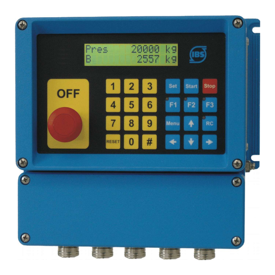
Page 12: Operating And Display Elements
Operating and display elements 3 Operating and display elements 3.1 Display The LCD display has two lines of 16 characters each. The character height is approx. 10 mm. An LCD back-light is available in version –SB. The upper LCD indicates the preselected quantity. The lower LCD indicates the cur- rent quantity batched. -
Page 13: Operation
Operation 4 Operation The upper line of the display indicates the preset quantity. In programming mode, the function to be executed is displayed. The lower line indicates the quantity batched. In programming mode, the value of the function or setting is shown. You can switch the lower display to flow indication with the [#] key. -
Page 14: Batching With The Batching Master
Operation 4.2 Batching with the Batching Master You must press the [Reset] key before the first batching process. The last preselec- tion is reset. Enter the preselected quantity using the numeric keys [1 to 9]. A decimal point will be displayed in a fixed position. - Page 15 Operation Lower Display Upper Display Fault No. Fault Type ERR M.-range mA2 Preselected Analogue input 2 altern. with batched quantity quantity measurement range violation ERR M.-range mA3 Preselected Analogue input 3 altern. with batched quantity quantity measurement range violation ERR MIN. FLOW Preselected 1024 Flow-rate lower than...
-
Page 16: Programming
Operation 4.4 Programming To enter the programming level, press the Menu key. The Batching Master displays the current software version and the instrument number. A checksum has to be gen- erated to check the certification data. If a sub-menu is selected, you can access the next level using the key. A code is requested if one has been entered. -
Page 17: Terminal Assignment
Terminal assignment 5 Terminal assignment Terminal Function Remark Page Power supply 1 + Power supply 1 - Power supply 2 + not usesd Power supply 2 - not used Pulse input 1 + Pulse input 1 - Pulse input 2 + Pulse input 2 - 4/20 mA analoge input 1+ 4/20 mA analoge input 1-... - Page 18 Interface RS485 1 GND Interface RS485 1 A - Interface RS485 2 B + Interface RS485 2 GND Interface RS485 2 A - Digital output „OFF pressed“ only for Batching Master 110 Digital output „OFF pressed“ only for Batching Master 110...
Need help?
Do you have a question about the Batching Master 110 and is the answer not in the manual?
Questions and answers