
Related Manuals for Voltech DC1000A

Summary of Contents for Voltech DC1000A
- Page 1 VOLTECH INSTRUMENTS DC1000A Precision DC Bias Current Source User Manual DC1000A User Manual (98-102 issue 3)
- Page 2 This DC current source should give you many years of reliable use. Should you experience any difficulty during the set up or use of your Voltech product, please do not hesitate to contact either your local supplier or one of our main offices.
-
Page 3: Table Of Contents
ETER WITH 3.4. LCR M GPIB DC1000A RS232 ..........43 ONNECTING A ONTROL ETER WITH WITH USING THE DC1000A WITH AN ATI TRANSFORMER TESTER ..............44 4.1. DC1000A PC) ....................44 ONNECTING THE WITH AN 4.2. DC1000A PC) ..................45 ONNECTING... - Page 4 YSTEM 5.2. DC1000A’ AT5600 ............. 47 ONNECTING ULTIPLE S WITH AN AFETY YSTEM USING THE DC1000A WITH A VOLTECH AT5600 OR ATI AND PC .............. 50 6.1. DC1000A AT5600 PC................50 ONNECTING THE WITH AN I AND 6.2. AT C ............................
- Page 5 DC1000A User Manual (98-102 issue 3)
-
Page 6: Introduction
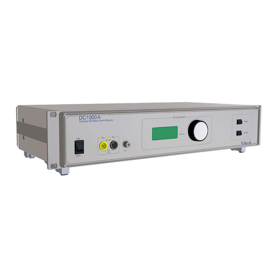
1. Introduction 1.1. What is the DC1000A? The DC1000A is a DC Bias current source that can generate between 0 and 25A. Up to twenty (20) DC1000A’s can simply be joined together in parallel to produce up to 500A. The DC1000A can be used with almost any LCR meter and with the AT-series transformer testers –... -
Page 7: Warranty
Customer and that for a period of one year (12 months) from such time Voltech will repair or replace any Product which does not comply with this warranty PROVIDED ALWAYS THAT the Company’s liability under this... -
Page 8: Limitation Of Warranty
It shall be deemed to exclude all other warranties and conditions whether express or implied and whether arising by common law statute or otherwise. Voltech reserve the right to waive this benefit in any event where it is clear upon inspection that the cause of the failure is due to customer misuse. -
Page 9: Health & Safety
CHECK YOUR LINE INPUT VOLTAGE SETTING BEFORE CONNECTING TO SUPPLY. A Use a flat-headed screwdriver to pull the fuse drawer out. B: Rotate the gray voltage selector to select the correct voltage for your location DC1000A User Manual (98-102 issue 3) -
Page 10: Hygiène Et Sécurité - Français
Toutefois, le fabricant se réserve le droit de modifier le contenu, les caractéristiques du produit ainsi que les critères de performance sans préavis. Voltech décline toute responsabilité quant à l'installation inappropriée, négligente ou incorrecte de l'instrument par l'utilisateur, par des moyens manuels ou automatisés. -
Page 11: Gesundheit Und Sicherheit - Deutsch
Benutzer (manuell oder automatisch) wird keine Haftung übernommen. PRÜFEN SIE VOR DEM ANSCHLUSS AN DEN NETZSTROM DIE SPANNUNGSEINSTELLUNG FÜR IHREN LEITUNGSEINGANG. A: Die Sicherungsschublade mit einem Flachklingen- Schraubendreher herausziehen. B: Den grauen Spannungswähler auf die richtige Spannung für Ihren Standort drehen. DC1000A User Manual (98-102 issue 3) -
Page 12: Salud Y Seguridad - Español
DE CONECTAR EL EQUIPO A LA RED. A Use un atornillador de punta plana para extraer la caja del fusible. B: Gire el reloj gris selector de voltaje apuntando al voltaje correcto de su red local. DC1000A User Manual (98-102 issue 3) -
Page 13: Salute E Sicurezza - Italiano
PROPRIA LINEA ELETTRICA PRIMA DI COLLEGARE L’APPARECCHIO. Usare un cacciavite a punta piatta per estrarre il cassettino dei fusibili. B. Ruotare il selettore grigio della tensione per selezionare la tensione corretta in base alla linea elettrica usata. DC1000A User Manual (98-102 issue 3) -
Page 14: Gezondheid En Veiligheid - Nederlands
CONTROLEER DE INSTELLING VAN UW LIJNINGANGSSPANNING VOORDAT DE VOEDING WORDT AANGESLOTEN. A: Gebruik een schroevendraaier met platte kop om de zekeringlade uit te trekken. B: Draai de grijze spanningkeuzeschakelaar om de juiste spanning voor uw locatie te selecteren. DC1000A User Manual (98-102 issue 3) -
Page 15: Sundhed Og Sikkerhed - Dansk
KONTROLLÉR DIN LINJEUDGANGENS INDSTILLINGER FOR INDGANGSSPÆNDING FØR TILSLUTNING TIL FORSYNINGEN. A: Brug en kærvskruetrækker til at trække sikringsskuffen ud. B: Drej den grå spændingsvælger for at vælge den korrekte spænding for din placering DC1000A User Manual (98-102 issue 3) -
Page 16: Hälsa Och Säkerhet - Svenska
KONTROLLERA SPÄNNINGSINSTÄLLNINGEN FÖR INGÅNGSLINJEN INNAN DU ANSLUTER TILL ELFÖRSÖRJNINGEN. A: Använd en skruvmejsel för att dra ut säkringslocket. B: Vrid den grå spänningsomkopplaren för att välja rätt spänning för din plats. DC1000A User Manual (98-102 issue 3) -
Page 17: Terveys Ja Turvallisuus - Suomi
Valmistaja ei ole millään tavoin korvausvelvollinen laitteen sopimattomasta, huolimattomasta tai virheellisestä käytöstä käyttäjän toimesta manuaalisesti tai automaattisesti. TARKISTA LINJAN TULOLIITÄNNÄN JÄNNITEASETUS ENNEN LIITTÄMISTÄ VERKKOVIRTAAN. A: Vedä sulakekotelo esiin käyttämällä tasapäistä ruuvitalttaa. B: Kierrä harmaata jännitteenvalitsinta ja valitse alueella käytössä oleva jännite. DC1000A User Manual (98-102 issue 3) -
Page 18: Zdraví A Bezpečnost - Čeština
či pomocí automatizovaných prostředků) neneseme žádnou odpovědnost. PŘED PŘIPOJENÍM ZDROJE NAPÁJENÍ ZKONTROLUJTE NASTAVENÍ VSTUPNÍHO NAPĚTÍ. A: Pomocí plochého šroubováku vytáhněte pojistkovou zásuvku. B: Otočte šedým voličem napětí na správnou hodnotu napětí pro vaši oblast. DC1000A User Manual (98-102 issue 3) -
Page 19: Munkavédelem - Magyar
HÁLÓZATBA VALÓ BEKÖTÉS ELŐTT ELLENŐRIZZE A HÁLÓZATI TÁPFESZÜLTSÉGET. A: Lapos csavarhúzóval húzza ki a helyéről a biztosítót. B: Fordítsa el a szürke feszültség választó kapcsolót a helyi megfelelő feszültség kiválasztására DC1000A User Manual (98-102 issue 3) -
Page 20: Bezpieczeństwo I Higiena Pracy - Polski
PRZED PODŁĄCZENIEM DO ZASILANIA NALEŻY SPRAWDZIĆ USTAWIENIE NAPIĘCIA WEJŚCIOWEGO LINII. A: Użyć płaskiego śrubokręta do wyciągnięcia oprawy bezpiecznika. B: Obrócić szary wybierak napięcia w celu wyboru prawidłowego napięcia dla lokalizacji użytkownika. DC1000A User Manual (98-102 issue 3) -
Page 21: Sağlık Ve Güvenlik Bilgileri - Türkçe
üretici ve satıcıya hiçbir sorumluluk doğurmayacaktır. ELEKTRİK KAYNAĞINA BAĞLAMADAN ÖNCE HATTINIZIN GİRİŞ VOLTAJ AYARINI KONTROL EDİNİZ. A: Düz başlı bir tornavida kullanarak sigortayı dışarı çıkarınız. B: Gri voltaj seçiciyi kullanarak cihazınızı kullandığın yerdeki voltaja ayarlayınız. DC1000A User Manual (98-102 issue 3) -
Page 22: Safety Precautions
ONLY. This ensures the safety of the instrument and the user when normal precautions are followed. This product can be used with a safety system and the Voltech series of AT testers (see Chapter 5 for details). It is the responsibility of the user to ensure that satisfactory risk assessments have been carried out and that the safety equipment is fit for purpose and in good working order. -
Page 23: Sicherheitsvorkehrungen - Deutsch
1.5.3 Sicherheitsvorkehrungen – Deutsch Im Inneren der DC1000A befinden sich keine vom Benutzer wartbaren Teile. Im Reparaturfall bringen Sie das Gerät bitte zu einem von Voltech autorisierten Servicecenter. Nur träge Feinsicherungen (5 x 20 mm, 3,15 A (66-024)) verwenden ... -
Page 24: Precauzioni Di Sicurezza - Italiano
Questo prodotto può essere usato con un sistema di sicurezza e con i tester Voltech Serie AT (v. Capitolo 5 per maggiori informazioni). Spetta all’utilizzatore la responsabilità di garantire che siano condotte valutazioni soddisfacenti in termini di sicurezza e idoneità... -
Page 25: Sikkerhedsforanstaltninger - Dansk
1.5.7 Sikkerhedsforanstaltninger - dansk Der er ingen dele inden i DC1000A, som kan serviceres af brugeren. Send enheden tilbage til et Voltech-godkendt servicecenter for eventuelle nødvendige reparationer. Brug kun sikringer af typen og effekten 3.15AT 5X20 OVERSPÆNDING (66-024) ... -
Page 26: Varotoimenpiteet - Suomi
1.5.9 Varotoimenpiteet – suomi DC1000A:n sisällä ei ole käyttäjän huollettavissa olevia osia. Jos laite tarvitsee korjausta, palauta se Voltechin hyväksymään huoltoliikkeeseen. Käytä vain sulakkeita, joiden tyyppi ja luokitus on 3,15 AT 5 × 20 VIRTAPIIKKISUOJAUS (66-024) DC1000A on valmistettu standardin EN61010-1, saastumisaste 2 ja asennusluokka II mukaisesti: VAIN SISÄKÄYTTÖÖN. -
Page 27: Biztonsági Óvintézkedések - Magyar
Ez biztosítja a berendezés és a felhasználó biztonságát a szokásos óvintézkedések betartása mellett. E termék együtt használható a biztonsági rendszerrel és a Voltech AT sorozatú vizsgálókészülékekkel (lásd a részleteket az 5. fejezetben). A felhasználónak kell biztosítania a megfelelő kockázatértékelések elvégzését és azt, hogy a biztonsági berendezés megfeleljen a rendeltetésének és jó... -
Page 28: Güvenlik Tedbirleri - Türkçe
Bu ürün, bir güvenlik sistemiyle ve Voltech serisi AT test cihazlarıyla (ayrıntılı bilgi için 5. Bölüme bakınız) birlikte kullanılabilir. Gerekli ve yeterli risk değerlendirmelerini yapmak ve güvenlik cihazının iş... -
Page 29: Package Contents
Also given are the Voltech part numbers (xx- xxx), in case you’d like to order spares. 1 x DC1000A CD (88-297) – Which contains the demo DC1000 PC software and an electronic version of the user manual. -
Page 30: Accessories
The Voltech Part number for the RS232 cable supplied with your AT Product that is used to interface with your DC1000A is 77-015 (9way-9way F-F Editor Cable). If you are using the DC1000A with a Voltech AT5600 then please contact Voltech for a “Y” cable (250-031) for easy connection to Safety System and AT5600. - Page 31 DC1000A User Manual (98-102 issue 3)
-
Page 32: Getting Started
The DC1000A is designed with ease of use and speed of testing in mind. The following is a description of the functions on both the front and rear panels of the DC1000A, to help you familiarize yourself with the basic operation of the instrument. - Page 33 Rotate to set the output current of the DC1000A. 7. Output Enable Button/LED Momentary button used to enable or disable the output current of the DC1000A. A green LED indicates the status of the output. The LED lights to indicate that the output is turned 8.
-
Page 34: Rear Panel Description
RS232 OUT port of another DC1000A. 2. RS232 OUT This serial port is used to connect to the RS232 IN port of another DC1000A, or a PC used for controlling an AT series transformer tester and DC1000A combination. - Page 35 DC1000A User Manual (98-102 issue 3)
-
Page 36: Using The Dc1000A With A Lcr Meter
Open circuit (OC) compensation: i) Short Amp Hi from the DC1000A with the LCR Hi. Short Amp Lo from the DC1000A with the LCR Lo. These are shorted separately. See Figure 4 below. - Page 37 DC1000A (3) is connected with Hi side of LCR meter (1) For the opposite side of device under test connect Lo side of DC1000A (4) to Lo side of LCR meter (2). Connect the (Earth) from the DC1000A (Front Panel) to the LCR meter earth terminal with a cable length of 600mm or shorter.
- Page 38 G. Adjustments can be made to the DC1000A current while the output is enabled, using the rotary encoder. It is also important to note that you should not disconnect the energized device under test. Disconnection while energized could cause damage.
-
Page 39: Connecting Multiple Dc1000A S With Alcr Meter
You can generate up to 500A as a maximum by connecting up to 20 DC1000As together in parallel. Either the first DC1000A or a PC can be used to control all the other DC1000As in the chain – automatically adjusting their output current to allow you to easily achieve the results you require. - Page 40 Connect the 9-Way RS232 cable (77-046) between the RS232 OUT of the first DC1000A in your chain and the RS232 IN of the second DC1000A, using the cable provided with your DC1000A. Then, if you have more than two DC1000A’s, connect the RS232 OUT of the second DC1000A in your chain to the RS232 IN of the third.
-
Page 41: Factors To Consider To Insure Proper Measurements With Adc1000A And Lcr Meter
To obtain accurate measurements with an LCR meter, measurement compensation must always be performed to reduce the effects of adding the DC1000A and cabling in parallel with the part under test. With most LCR meters there are two different types of compensation: Open Circuit and Short Circuit. -
Page 42: Connecting Apc To Control Adc1000A And Lcr Meter With Rs232
D. When connecting a LCR meter and DC1000A to the device under test, be sure the Hi side of DC1000A 9 is connected with Hi side of LCR meter 7 and use the opposite side of device under test to connect Lo side of DC1000A 10 to Lo side of LCR meter 8. -
Page 43: Connecting Apc To Control Lcr Meter With Gpib And Dc1000A With Rs232
C. Use the IEEE-488 cable to connect PC IEEE-488 port 5 to LCR meter IEEE-488 port 6. D. When connecting a LCR meter and DC1000A to the device under test, be sure Hi side of DC1000A 9 is connected with Hi side of LCR meter 7 and use opposite side of device under test to connect Lo side of DC1000A 10 to Lo side of LCR meter 8. -
Page 44: Using The Dc1000A With An Ati Transformer Tester
4. Using the DC1000A with an ATi Transformer Tester 4.1. Connecting the DC1000A with an ATi (no PC) When an ATi and DC1000A are used in combination this easily allows you to automate your production testing. Setup with an ATi and DC1000A is quick and easy. -
Page 45: Connecting Multiple Dc1000As With An Ati (No Pc)
4.2. Connecting Multiple DC1000As with an ATi (No PC) When you connect up to 20 DC1000A(s) in parallel you are able to test up to 500A. Everything you need to connect multiple DC1000As is provided in the box. Please reference Figure 12 for connection details. -
Page 46: Using The Dc1000A With An At5600 And Safety System
When using your DC1000A(s) with a Voltech AT5600 series transformer tester, a Safety Interlock Y splitter lead (250-031) must be used on the safety system with the AT connected on the AT side of the Y, with the second Y going to the DC1000A safety interlock IN. -
Page 47: Connecting Multiple Dc1000A's With An At5600 And Safety System
B. Use a 9way-9way M-F straight-through lead (77-046) to connect Safety Interlock OUT (port 4) of DC1000A # 1 to the Safety Interlock IN (port 5) of DC1000A #2. C. Use a 9way-9way M-F straight-through lead (77-046) to connect AT5600 Aux (Port 6) toRS232 In (port 7) of DC1000A #1. - Page 48 For optimum safety, ease of use and test speed, Voltech recommends the use of a safety light curtain. Voltech can provide a “Y” cable (250-031) for connection between a light curtain and the DC1000A and the AT5600 transformer tester. The cable has been optimized for use with the safety light curtain.
- Page 49 DC1000A User Manual (98-102 issue 3)
-
Page 50: Using The Dc1000A With A Voltech At5600 Or Ati And Pc
Voltech AT5600 or ATi and PC 6.1. Connecting the DC1000A with an AT5600 or ATi and A PC can be used to control the AT5600 or ATi and DC1000A(s) with any communications software you use. (E.g. Voltech AT Editor Software, or Voltech DC1000 PC Software). -
Page 51: At Compensation
LSBX, and ZBX) must be installed on the AT being used. As with all Voltech AT tests, these are provided on a per AT basis – so no matter how many DC1000As you have connected, one test purchase will cover all DC1000As attached to your AT. -
Page 52: Using Ir, Hpdc, Hpac, Dcrt, Acrt, Dcvb, Acvb T
Figure 16a illustrates this setup. In this example the fixture and test program should be constructed so that the Ahi and ALo connections from the DC1000A are hard wired to Nodes 3 & 4, which are then used as LO in Hi Pot testing. -
Page 53: Sing Ilk, Surg, Magi, Strw, Watt, Voc Tests
2 pole safety isolation relay, controlled by the User Port. The relays should be selected with suitable isolation to safely isolate the DC1000A from any voltages you wish to apply using these tests. -
Page 54: Programming The At Tests Using The At Editor
The measured voltage is divided by the current to obtain a complex impedance and the inductance is calculated. On selecting ‘LSBX Inductance with External Bias (Series Circuit)’ from the ‘Available Tests’ window, a dialogue box will be displayed. Fig 17 DC1000A User Manual (98-102 issue 3) - Page 55 Enter a nominal value and then the limits as negative and positive values. >< Enter minimum and maximum values. > Enter just a minimum value. < Enter just a maximum value. 5. Select OK. The test specification will then be displayed in the program window. DC1000A User Manual (98-102 issue 3)
-
Page 56: Lpbx - Inductance With External Bias (Parallel Circuit)
The measured voltage is divided by the current to obtain a complex impedance and the inductance is calculated. On selecting ‘LPBX Inductance with External Bias (Parallel Circuit) from the ‘Available Tests’ window, a dialogue box will be displayed. Fig 18 DC1000A User Manual (98-102 issue 3) - Page 57 Enter a nominal value and then the limits as negative and positive values. >< Enter minimum and maximum values. > Enter just a minimum value. < Enter just a maximum value. 5. Select OK. The test specification will then be displayed in the program window. DC1000A User Manual (98-102 issue 3)
-
Page 58: Zbx - Impedance With External Bias
6.5.3. ZBX – Impedance with External Bias The Winding Impedance with External Bias test measures the impedance of a selected winding while applying a DC current from the DC1000A through the winding. An AC voltage is also applied across the winding from the AT. - Page 59 Enter a nominal value and then the limits as negative and positive values. >< Enter minimum and maximum values. > Enter just a minimum value. < Enter just a maximum value. 5. Select OK. The test specification will then be displayed in the program window. DC1000A User Manual (98-102 issue 3)
-
Page 60: Editor - High Terminal Conflict
Any program downloaded with this configuration will be cancelled, and error message will appear: - To correct this, the ATP test program should be changed so that the DC tests (LSBX, LPBX and ZBX) are always on the LO side of any HV tests. DC1000A User Manual (98-102 issue 3) -
Page 61: Rs232 Communication
For your convenience, listed below are the RS232 commands you can use to control the DC1000A remotely. The baud rate that you should use to communicate with the DC1000A is 9600, with 8 data bits, parity is none, 1 stop bit, and there is hardware flow control. - Page 62 The unit will respond with “D_STAT,0,status <cr> <lf>” where status is a single integer indicating the status of the unit and any other unit attached. If everything is OK, 0 or 1 will be returned. If not, then a status number will be returned. DC1000A User Manual (98-102 issue 3)
- Page 63 Messages returned The following will be returned; Serialnumber <cr> <lf> where serialnumber is the serial number of the DC1000A (Serial number returned will always be 12 digits, if the queried unit’s serial number has less characters, then spaces will fill it out to 12.
- Page 64 DC1000A User Manual (98-102 issue 3)
-
Page 65: Status Codes
8.2. Correcting Status Code Errors Status Code Example You enable the output of the DC1000A and the number E257 is shown on the display. The only combination to create this number is 256 + 1 (bits 8 and 0) so this number is signally “on and all OK”... - Page 66 (it should be blowing loudly at high temperatures) and that all ventilation areas are free from obstructions. The DC1000A must not be operated in ambient temperatures above 40C. If the problem persists then contact Voltech for servicing information.
-
Page 67: Specifications
Accuracy on Supplied Current: ±0.5% of reading ±25mA. Compliance voltage: 5V pk. The above graph (red line) shows the error current expected per DC1000A, per Volt applied by the LCR meter. This assumes the LCR meter has been compensated to remove any errors caused by connections and fixturing. -
Page 68: Power Supply Voltage
DC1000A simultaneously. 9.6. Safety Interlock Protection for operators from back EMF when interlock connected to safety system. 9.7. Variable Speed Cooling Fan Runs fan at variable speed dependent on load and temperature for minimal noise. DC1000A User Manual (98-102 issue 3) -
Page 69: Service And Calibration
To confirm the accuracy of your product, a calibration check should be carried out every 12 months. Calibration adjustment is carried out using OEM Test Equipment and DC1000A Calibration Software. Adjustment can only be performed by an authorized Voltech service center. -
Page 70: Appendix
Short Circuit compensation (see Section 3, Figure 5 for connections): 1. Press “Measure Setup”, using soft key select “Correction”. 2. Move the cursor using the arrow button to highlight “Short” 3. Press the soft key to turn on. DC1000A User Manual (98-102 issue 3) - Page 71 Preferably use a fixture system where the part under test can be inserted and removed without moving any cabling. Any movement in the wiring will affect the measured values due to changes in the capacitance and mutual inductance between the cables DC1000A User Manual (98-102 issue 3)
-
Page 72: The Dc1000A - How It Works
To guarantee the quality and performance of such a component it must be tested at real working conditions, including DC bias current, during manufacture. The revolutionary design of the DC1000A eliminates the need for bulky and inflexible DC Bias Supplies that are tied to a particular LCR meter and restrict test performance. - Page 73 In practice all transistors show a slope of the shown “real” characteristic. Even with constant base current, the collector current will tend to change with changing collector-emitter voltage. (See fig 2B). DC1000A User Manual (98-102 issue 3)
- Page 74 DC current and LCR meter signal level is very difficult if not impossible. Until now, DC Bias supplies were restricted to a particular manufacturer's LCR model number in an attempt to minimize these errors. DC1000A User Manual (98-102 issue 3)
-
Page 75: The Solution
11.2.3. The Solution With the DC1000A's correction circuit, these errors are essentially eliminated by the use of an inductor placed inside an AC control loop. A sense winding on the inductor produces a voltage proportional to the AC voltage across it. - Page 76 The below graph demonstrates the massive reduction in error current, by comparing the error current caused by the DC1000A both with and without the correction circuit operating. Fig 4 Effect of DC1000A correction circuit on error current.
-
Page 77: Advantages
3. Now open and short compensation can be applied by the LCR meter as usual to make measurements free from all stray effects. 4. The DC1000A requires no special connection to the LCR meter, or knowledge of its settings, making it suitable for use with any LCR meter. -
Page 78: Safety And Emc Compliance
The product herewith complies with the requirements of the EMC Directives 2004/108/EC and the Low Voltage Directive 2006/95/EC Signed for on behalf of Voltech Instruments Ltd. Dr John Ford, Managing Director 16 June 2016 DC1000A User Manual (98-102 issue 3) - Page 79 Voltech Instruments, Inc. has an intensive program of design and development that may alter product specification. Voltech Instruments, Inc. reserves the right to change the product specification at any time, and without notice. No part of this publication may be produced or...
Need help?
Do you have a question about the DC1000A and is the answer not in the manual?
Questions and answers