Table of Contents
Advertisement
Quick Links
Advertisement
Table of Contents

Subscribe to Our Youtube Channel
Related Manuals for Leica Geosystems CS10


Summary of Contents for Leica Geosystems CS10
- Page 1 Leica CS10/CS15 User Manual Version 4.0 English...
- Page 2 The type and serial number of your product are indicated on the type plate. tion Enter the type and serial number in your manual and always refer to this information when you need to contact your agency or Leica Geosystems authorised service work- shop. Type: _______________ Serial No.:...
- Page 3 Important paragraphs which must be adhered to in practice as they enable the product to be used in a technically correct and efficient manner. CS10/CS15, Introduction...
- Page 4 SD is a trademark of the SD Card Association All other trademarks are the property of their respective owners. Validity of this This manual applies to the CS10 and CS15 field controllers. Differences between the manual various models are marked and described.
- Page 5 Included are detailed descriptions of Reference special software/hardware settings and software/hard- Manual ware functions intended for technical specialists. Refer to the following resources for all CS10/CS15 documentation/software: • the Leica Viva Series DVD • https://myworld.leica-geosystems.com myWorld@Leica Geosystems (https://myworld.leica-geosystems.com) offers a wide range of services, information and training material.
- Page 6 Service Description myProducts Simply add all Leica Geosystems products that you and your company own. View detailed information on your products, buy additional options or Customer Care Packages (CCPs), update your products with the latest software and keep up-to-date with the latest documentation.
-
Page 7: Table Of Contents
Page Description of the System Overview Terminology System Concept 1.3.1 Software Concept 1.3.2 Power Concept 1.3.3 Data Storage Concept CS Components 1.4.1 CS10 1.4.2 CS15 Docking Station Components User Interface Keyboard Operating Principles Operation Equipment Setup CS10/CS15, Table of Contents... -
Page 8: Cs10/Cs15, Table Of Contents
Power Functions Batteries 3.3.1 Operating Principles 3.3.2 Changing the Battery 3.3.3 Charging the Battery Working with the Memory Device LED Indicators on CS10 /CS15 LED Indicators on CTR16 LED Indicators on GS08 /GS12 Using the Digital Camera Care and Transport Transport... - Page 9 General Introduction Intended Use Limits of Use Responsibilities Hazards of Use Electromagnetic Compatibility EMC FCC Statement, Applicable in U.S. Technical Data CS10 /CS15 Technical Data GS05 /GS06 Technical Data 6.2.1 Tracking Characteristics 6.2.2 Accuracy 6.2.3 Technical Data CTR16 Technical Data GS08 /GS12 Technical Data 6.4.1...
- Page 10 CS10/CS15, Table of Contents 6.4.3 Technical Data Antennas Technical Data Conformity to National Regulations 6.6.1 CS10 6.6.2 CS15 6.6.3 CTR16 6.6.4 GS08 6.6.5 GS12 International Limited Warranty, Software Licence Agreement Appendix A Pin Assignments and Sockets CS10 /CS15 GS08 /GS12...
-
Page 11: Description Of The System
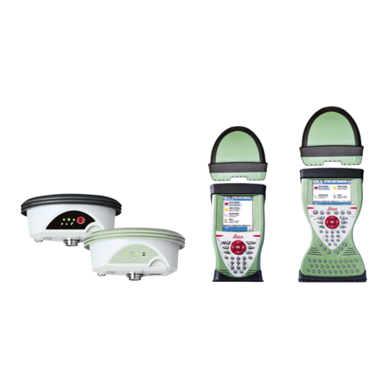
Description of the System Overview System compo- nents CTR16 GS08 GS06 GS05 CS10 CS15 GS12 CS_028 CS10/CS15, Description of the System... -
Page 12: Terminology
CS10/CS15, Description of the System Terminology CS general descrip- CS is a collective term describing the various models (CS10/CS15) of the multi- tion purpose field controller which is used with GNSS and TPS instruments. CS available models Basic (CS10/CS15) Radio (CS10/CS15) 3.5G (CS10/CS15) - Page 13 Field controller with an integrated radio modem. This field controller has a colour display. CS15 Field controller with an integrated radio modem. This field controller has a colour display. All devices contain the same spread spectrum transceiver radio modem. CS10/CS15, Description of the System...
-
Page 14: System Concept
CS10/CS15, Description of the System System Concept 1.3.1 Software Concept Software for all CS Software type Description models CS firmware This software includes: (CS_xx.fw) - The language-specific version of Windows CE. - The basic functionality of the CS. Software for the... - Page 15 • A message will appear when the upload is complete. Ensure that a Leica SD card or a Leica CF card is inserted into the CS field controller before starting the upload. CS10/CS15, Description of the System...
- Page 16 CS10/CS15, Description of the System Software for Description GS05/GS06 The software is stored in the flash RAM of the GS05/GS06. GS firmware update instructions • Download the most recent GS firmware file from https://myworld.leica-geosystems.com. Refer to "Intro- duction". • Connect the CS field controller to your PC. Refer to "3.1.8 Connecting to a Personal Computer".
- Page 17 Refer to the Leica Viva TechRef (Connections.. - GPS connection wizard). • Start the upload. Refer to the Leica Viva GNSS Getting Started Guide (Appendix B Uploading System Files). • A message will appear when the upload is complete. CS10/CS15, Description of the System...
-
Page 18: Power Concept
CS10/CS15, Description of the System 1.3.2 Power Concept General Use the Leica Geosystems batteries, chargers and accessories or accessories recom- mended by Leica Geosystems to ensure the correct functionality of the instrument. Power options Model Power supply all CS models... - Page 19 Model Power supply If an external power supply is connected and the internal battery is inserted, then the external power is used. CS10/CS15, Description of the System...
-
Page 20: Data Storage Concept
All CS field controllers have an internal memory fitted as standard. Available capacity: 1 GB. While other SD cards or CompactFlash cards can be used, Leica Geosystems recommends to only use Leica SD cards or Leica CompactFlash cards and is not responsible for data loss or any other error that can occur while using a non-Leica card. - Page 21 Data can be transferred in various ways. Refer to "3.1.8 Connecting to a Personal Computer". CompactFlash cards and SD cards can directly be used in an OMNI drive as supplied by Leica Geosystems. Other PC card drives can require an adaptor. CS10/CS15, Description of the System...
-
Page 22: Cs Components
CS10/CS15, Description of the System CS Components 1.4.1 CS10 Upside of CS10 a) Slot Cover b) Screen c) Keyboard d) Port cover e) Power socket USB A Host port g) Docking station contacts h) LEMO port (USB and serial) USB Mini port... - Page 23 Hand strap bottom clips b) Hand strap c) Battery compartment d) Digital camera e) Hand strap top clips Slots g) Slot cover h) Stylus GS05 contacts CompactFlash card slot k) SIM card slot SD card slot CS_008 CS10/CS15, Description of the System...
-
Page 24: Cs15
CS10/CS15, Description of the System 1.4.2 CS15 Upside of CS15 a) Slot cover b) Screen c) Keyboard d) Port cover e) Power socket USB A Host port g) Docking station contacts h) LEMO port (USB and serial) USB Mini port... - Page 25 Hand strap bottom clips b) Hand strap c) Battery compartment d) Digital camera e) Hand strap top clips Slots g) Slot cover h) Stylus GS06 contacts CompactFlash card slot k) SIM card slot SD card slot CS_007 CS10/CS15, Description of the System...
-
Page 26: Docking Station Components
CS10/CS15, Description of the System Docking Station Components Docking station a) Power socket b) USB port c) Docking station bracket d) Docking station contacts e) GEV223 data cable CS_020... -
Page 27: User Interface
User Interface Keyboard Keyboard display CS10 a) Home b) ON/OFF c) Arrow keys, OK d) Fn e) ± key Brightness g) Keyboard illumination h) Favourites Enter PQRS WXYZ k) Backspace Volume m) Numeric keys CS_005 CS10/CS15, User Interface... - Page 28 CS10/CS15, User Interface Keyboard display a) Home CS15 b) Arrow keys, OK c) ON/OFF d) Fn e) ± key Numeric keys g) Brightness h) Keyboard illumination Function keys F7 - F12 CAPS Lock k) Function keys F1 - F6 Favourites...
- Page 29 Clears all entry at the beginning of user input. Clears the last character during user input. Leaves the current screen without storing any changes. Switches between the first and second level of func- tion keys. Space Enters a blank. CS10/CS15, User Interface...
- Page 30 Starts the edit mode for editable fields. Opens a selectable list. ON/OFF If CS10/CS15 already off: Turns on CS10/CS15 when held for 2 s. If CS10/CS15 in stand-by mode: Turns on CS10/CS15 when held < 2 s. If CS10/CS15 already on: •...
- Page 31 Function Arrow keys Move the focus on the screen. Selects the highlighted line and leads to the next logical menu/ dialog. Starts the edit mode for editable fields. Opens a selectable list. CS10/CS15, User Interface...
- Page 32 CS10/CS15, User Interface Key combinations Function Hold Fn while pressing 4. Increase the screen bright- ness. Hold Fn while pressing 7. Decrease the screen bright- ness. Hold Fn while pressing 6. Increase the volume for acoustic warning signals, beeps and keypresses on the CS field controller.
-
Page 33: Operating Principles
To accept data entered into an editable Tap on the screen outside of the editable field and exit the edit mode field. To open a context-sensitive menu Tap on the item and hold for 2 s. CS10/CS15, User Interface... -
Page 34: Operation Equipment Setup
CS10/CS15, Operation Operation Equipment Setup 3.1.1 Fixing the Display Foil to the CS Fixing the display foil to the CS step- by-step CS_029 Step Description Ensure that the display of the CS is free of dust and grease. The non-reflecting display foil has a silver-coloured sticker to peel away the carrier foil from the actual display foil. - Page 35 Peel away the carrier foil bit by bit and smooth it out slowly onto the display. Potential air bubbles between display and display foil have to be smoothed out using the included microfibre cloth. Do not use sharp objects! CS10/CS15, Operation...
-
Page 36: Fixing A Hand Strap To The Cs
CS10/CS15, Operation 3.1.2 Fixing a Hand Strap to the CS Fixing the CS to a hand strap step- by-step CS_009 Step Description Turn the CS field controller over. Take the end of the hand strap and clip it to the base of CS field controller. - Page 37 Step Description Adjust the length of the hand strap. CS10/CS15, Operation...
-
Page 38: Fixing The Slot Cover To The Cs
CS10/CS15, Operation 3.1.3 Fixing the Slot Cover to the CS Fixing the slot cover to the CS step-by-step CS_016 Step Description Press the screwdriver end of the supplied stylus on the quarter-turn screws and loosen them. Remove the slot cover. -
Page 39: Inserting And Removing A Sim Card
CS_019 Description The SIM card is inserted into a slot inside the top of the CS10/CS15. Loosen the screws inside the slot cover on top of the CS10/CS15 using the screwdriver end of the stylus. Detach the slot cover from the CS10/CS15. - Page 40 Attach the slot cover and tighten the screws. To remove the card, detach the slot cover of the CS10/CS15. Gently press the top of the card to release it from the slot. Remove the SIM card and attach the slot cover.
-
Page 41: Setting Up The Docking Station
Step Description Hold the docking station bracket as shown in the illustration in relation to the docking station rack. Slightly press the holder into the docking station rack. A click can be felt when the holder is secure. CS10/CS15, Operation... -
Page 42: Setting Up As Handheld Gnss
Attaching the GS05 to the CS10 step- by-step CS_011 Step Description Detach the slot cover from the CS10. Refer to "3.1.3 Fixing the Slot Cover to the CS". Check the position of the contacts in the inner surface of the GS05. - Page 43 Step Description Attach the GS05 to the CS10. Press the screwdriver end of the supplied stylus on the quarter-turn screws and tighten them. To achieve the optimal satellite tracking performance, mount the AS05 (external GNSS antenna) on the GS05. CS10/CS15, Operation...
-
Page 44: Setting Up As Robotic
CS10/CS15, Operation 3.1.7 Setting up as Robotic Attaching the CTR16 to the CS15 step-by-step CS_031 Step Description Detach the slot cover from the CS15. Refer to "3.1.3 Fixing the Slot Cover to the CS". Check the position of the contacts in the inner surface of the CTR16. -
Page 45: Connecting To A Personal Computer
Leica Viva devices. Depending on the version (32bit or 64bit) of the oper- ating system on your PC, you have to select between the three setup files following: • SetupViva&GR_USB_32bit.exe • SetupViva&GR_USB_64bit.exe • SetupViva&GR_USB_64bit_itanium.exe The setup has to be run only once for all Leica Viva devices. CS10/CS15, Operation... - Page 46 CS10/CS15, Operation Step Description The Welcome to InstallShield Wizard for Leica Viva & GR USB drivers window appears. Ensure that all Leica Viva devices are disconnected from your PC before you continue! Next>. The Ready to Install the Program window appears.
- Page 47 For CS field controllers with DSUB9 connector, the GEV223 cable has to be used. Turn on the CS field controller. Plug the GEV234 cable into the USB port of the PC. The Found New Hard- ware Wizard starts up automatically. Check Yes, this time only. Next>. CS10/CS15, Operation...
- Page 48 CS10/CS15, Operation Step Description Check Install the software automatically (Recommended). Next>. The software for Remote NDIS based LGS CS Device will be installed on your Finish. The Found New Hardware Wizard starts up automatically a second time. Check Yes, this time only. Next>.
- Page 49 Plug the GEV234 cable into the USB port of the PC. For PCs with Windows XP operating system: ActiveSync starts up automatically. If does not start automatically, start ActiveSync. If not already installed, run the ActiveSync instal- lation program. CS10/CS15, Operation...
- Page 50 CS10/CS15, Operation Step Description Allow USB connections inside the Connection Settings window of Active- Sync. Click Explore in ActiveySync. The folders on the CS field controller are displayed under Mobile Devices. The folders of the data storage device can be found in StorageCard.
-
Page 51: Power Functions
Turn CS field controller off. Stand-by Put CS field controller into stand-by mode. In stand-by mode, CS field controller shuts down and reduces power consumption. Rebooting from stand-by mode is quicker than a cold start after turning off. CS10/CS15, Operation... - Page 52 CS10/CS15, Operation Option Description Lock keyboard Lock the keyboard. Option turns to Unlock keyboard. Turn off touch screen Disable touch screen. Option turns to Turn on touch screen. Reset... Perform one of the following options: • Restart (restarts Windows CE) •...
-
Page 53: Batteries
+10°C to +20°C/+50°F to +68°F if possible. • It is normal for the battery to become warm during charging. Using the chargers recommended by Leica Geosystems, it is not possible to charge the battery if the temperature is too high. •... -
Page 54: Changing The Battery
CS10/CS15, Operation 3.3.2 Changing the Battery Insert and remove the battery on the CS field controller step-by-step CS_010 Step Description Turn CS field controller over to gain access to the battery compartment. Push the slide fastener in the direction of the arrow with the open-lock symbol. - Page 55 Turn GS08/GS12 over to gain access to the battery compartment. Open the battery compartment by pushing the slide fastener in the direc- tion of the arrow with the open-lock symbol. Pull out the battery housing. The battery is attached to the housing. CS10/CS15, Operation...
- Page 56 CS10/CS15, Operation Step Description Hold the battery housing and pull the battery from the battery housing. A polarity of the battery is displayed inside the battery housing. This is a visual aid to assist in placing the battery correctly. Place the battery onto the battery housing, ensuring that the contacts are facing outward.
-
Page 57: Charging The Battery
(A) or the docking station (B) and an A/C plug. The power LED on the CS field controller switches on. When CS field controller’s battery is fully charged the LED switches off again. Refer to "LED indicators" for information about the power LED. CS10/CS15, Operation... - Page 58 Using the product after incorrect attempts were made to carry out repairs Precautions: Do not open the product. Only Leica Geosystems authorised service workshops are entitled to repair these products. The following advice is only valid for batteries, power adapter or docking station.
-
Page 59: Working With The Memory Device
Use it only within the specified temperature range. • Do not bend the card. • Protect the card from direct impacts. Failure to follow these instructions could result in data loss and/or permanent damage to the card. Insert and remove a CompactFlash card step-by-step CS_017 CS10/CS15, Operation... - Page 60 The CompactFlash card is inserted into a slot inside the top of the CS10/CS15. Refer to "Fixing the slot cover to the CS step-by-step". Loosen the screws inside the slot cover on top of the CS10/CS15 using the screwdriver end of the stylus. Detach the slot cover from the CS10/CS15.
- Page 61 Step Description The SD card is inserted into a slot inside the top of the CS10/CS15. Refer to "Fixing the slot cover to the CS step-by-step". Loosen the screws inside the slot cover on top of the CS10/CS15 using the screwdriver end of the stylus.
- Page 62 Description Attach the slot cover and tighten the screws. To remove the card, detach the slot cover of the CS10/CS15. Gently press the top of the card to release it from the slot. Remove the SD card and attach the slot cover.
-
Page 63: Led Indicators On Cs10/Cs15
LED Indicators on CS10/CS15 LED indicators Description The CS field controller has Light Emitting Diode indicators. They indicate the basic field controller status. Diagram a) Bluetooth LED b) Power LED CS_023 CS10/CS15, Operation... - Page 64 CS10/CS15, Operation Description of the LEDs IF the THEN Bluetooth green Bluetooth is in data mode and ready for connecting. purple Bluetooth is connecting. blue Bluetooth has connected. flashing blue data is being transferred Power LED power is off. green power is okay.
- Page 65 IF the THEN flashing red power is very low. The battery is being charged. CS10/CS15, Operation...
-
Page 66: Led Indicators On Ctr16
CS10/CS15, Operation LED Indicators on CTR16 LED indicators Description The CTR16 has a Light Emitting Diode indicator. It indicates the basic radio status. Diagram a) TPS radio LED CS_033 Description of the LEDs IF the THEN TPS radio LED green radio is in data mode and ready for connecting. - Page 67 IF the THEN purple radio is connecting. blue radio has connected. flashing blue data is being transferred. the CTR16 is not ready to be used. CS10/CS15, Operation...
-
Page 68: Led Indicators On Gs08/Gs12
CS10/CS15, Operation LED Indicators on GS08/GS12 LED indicators Description The GS08/GS12 instrument has Light Emitting Diode indicators. They indicate the basic instrument status. Diagram a b c Tracking LED (TRK) BT - Bluetooth LED (BT) Power LED (PWR) GS_120... - Page 69 Data is being transferred. PWR LED Power is off. green Power is okay. flashing green Power is low. The remaining time for which enough power is available depends on the type of survey, the temperature and the age of the battery. CS10/CS15, Operation...
-
Page 70: Using The Digital Camera
CS10/CS15, Operation Using the Digital Camera Overview Both CS field controllers are equipped with a digital camera located at the underside (refer to "1.4 CS Components"). If a hand strap or pole holder plate is mounted, the camera view is not limited. The camera application can be started from the desktop icon Camera or from the Start menu Start - Programs - Camera. - Page 71 Browse to the desired folder or create a new one. Name the picture. Press OK to save it and return to the camera view. Press Cancel to reject the picture and to return to the camera view without saving the picture. CS10/CS15, Operation...
-
Page 72: Care And Transport
Always carry the product in its transport container and secure it. Shipping When transporting the product by rail, air or sea, always use the complete original Leica Geosystems packaging, transport container and cardboard box, or its equiva- lent, to protect against shock and vibration. Shipping, transport... -
Page 73: Storage
Protect batteries from damp and wetness. Wet or damp batteries must be dried before storing or use. • A storage temperature range of -20°C to +30°C/-4°F to 86°F in a dry environ- ment is recommended to minimise self-discharging of the battery. CS10/CS15, Care and Transport... -
Page 74: Cleaning And Drying
CS10/CS15, Care and Transport Cleaning and Drying Product and acces- • Use only a clean, soft, lint-free cloth for cleaning. If necessary, moisten the cloth sories with water or pure alcohol. Do not use other liquids; these may attack the polymer components. - Page 75 Cables and plugs Keep plugs clean and dry. Blow away any dirt lodged in the plugs of the connecting cables. Connectors with Wet connectors must be dry before attaching the dust cap. dust caps CS10/CS15, Care and Transport...
-
Page 76: Safety Directions
CS10/CS15, Safety Directions Safety Directions General Introduction Description The following directions enable the person responsible for the product, and the person who actually uses the equipment, to anticipate and avoid operational hazards. The person responsible for the product must ensure that all users understand these... -
Page 77: Intended Use
Use after misappropriation. • Use of products with recognisable damages or defects. • Use with accessories from other manufacturers without the prior explicit approval of Leica Geosystems. • Inadequate safeguards at the working site, for example when measuring on roads. •... - Page 78 CS10/CS15, Safety Directions Warning Adverse use can lead to injury, malfunction and damage. It is the task of the person responsible for the equipment to inform the user about hazards and how to counteract them. The product is not to be operated until the user...
-
Page 79: Limits Of Use
The following advice is only valid for battery charger, power adapter and car adapter. Environment Suitable for use in dry environments only and not under adverse conditions. CS10/CS15, Safety Directions... -
Page 80: Responsibilities
Manufacturers of The manufacturers of non Leica Geosystems accessories for the product are respon- non Leica Geosys- sible for developing, implementing and communicating safety concepts for their... - Page 81 The person responsible for the product must ensure that it is used in accordance with the instructions. This person is also accountable for the training and the deployment of personnel who use the product and for the safety of the equipment in use. CS10/CS15, Safety Directions...
-
Page 82: Hazards Of Use
CS10/CS15, Safety Directions Hazards of Use Warning The absence of instruction, or the inadequate imparting of instruction, can lead to incorrect or adverse use, and can cause accidents with far-reaching human, material, financial and environmental consequences. Precautions: All users must follow the safety directions given by the manufacturer and the direc- tions of the person responsible for the product. - Page 83 Warning If computers intended for use indoors are used in the field there is a danger of elec- tric shock. Precautions: Adhere to the instructions given by the computer manufacturer regarding field use with Leica Geosystems products. CS10/CS15, Safety Directions...
- Page 84 Precautions: Do not use the product in a thunderstorm. Warning Using a battery charger not recommended by Leica Geosystems can destroy the batteries. This can cause fire or explosions. Precautions: Only use chargers recommended by Leica Geosystems to charge the batteries.
- Page 85 If battery terminals come in contact with jewellery, keys, metallised paper or other metals, short circuited battery terminals can overheat and cause injury or fire, for example by storing or transporting in pockets. Precautions: Make sure that the battery terminals do not come into contact with metallic objects. CS10/CS15, Safety Directions...
- Page 86 Using the product after incorrect attempts were made to carry out repairs Precautions: Do not open the product. Only Leica Geosystems authorised service workshops are entitled to repair these products. The following advice is only valid for batteries, power adapter or docking station.
- Page 87 Product-specific treatment and waste management information can be downloaded from the Leica Geosystems home page at http://www.leica- geosystems.com/treatment or received from your Leica Geosystems dealer. Warning Only Leica Geosystems authorised service workshops are entitled to repair these products. CS10/CS15, Safety Directions...
-
Page 88: Electromagnetic Compatibility Emc
Electromagnetic radiation can cause disturbances in other equipment. Although the product meets the strict regulations and standards which are in force in this respect, Leica Geosystems cannot completely exclude the possibility that other equipment may be disturbed. The product is a class A product when operated with the internal batteries. In a domestic environment this product may cause radio interference in which case the user may be required to take adequate measures. - Page 89 Although the product meets the strict regulations and standards which are in force in this respect, Leica Geosystems cannot completely exclude the possibility that the product may be disturbed by intense electromagnetic radiation, for example, near radio transmitters, two-way radios or diesel generators.
- Page 90 Precautions: Although the product meets the strict regulations and standards which are in force in this respect, Leica Geosystems cannot completely exclude the possibility that other equipment can be disturbed or that humans or animals can be affected. •...
-
Page 91: Fcc Statement, Applicable In U
Increase the separation between the equipment and the receiver. • Connect the equipment into an outlet on a circuit different from that to which the receiver is connected. • Consult the dealer or an experienced radio/TV technician for help. CS10/CS15, Safety Directions... - Page 92 CS10/CS15, Safety Directions Warning Changes or modifications not expressly approved by Leica Geosystems for compli- ance could void the user's authority to operate the equipment. Labelling CS10 CS_014 Labelling CS15 CS_015...
- Page 93 Labelling CTR16 CS_032 Labelling GS05, GS06 CS_012 CS10/CS15, Safety Directions...
- Page 94 CS10/CS15, Safety Directions Labelling GS08, GS12 This device complies with part 15 of the FCC Rules. Operation is subject to the following two conditions: (1) This device may not cause harm- ful interference, and (2) this device must accept any interference received, including inter- ference that may cause undesired operation.
- Page 95 SAR compliance for body-worn operating configurations is limited to specific belt- clips, holsters or similar accessory configurations that have no metallic component in the assembly providing at least 1.0 cm separation distance between the device and the body of the user. CS10/CS15, Safety Directions...
-
Page 96: Technical Data
CS10/CS15, Technical Data Technical Data CS10/CS15 Technical Data Design Glass reinforced polymer housing with optional integrated battery and radio modem. Control unit CS10 Display: VGA (480 x 640 pixels), graphics capable LCD, illumination, touch screen, colour Keyboard: 26 keys, illumination... - Page 97 0.245 0.125 0.045 Weight Type Weight [kg]/[lbs] CS10, with battery, internal radio and WLAN 0.720/1.587 CS15, with battery, internal radio and WLAN 0.870/1.918 Recording Data can be recorded on the SD card, CompactFlash card, USB stick or in the internal memory.
- Page 98 CS10/CS15, Technical Data Internal battery Type Battery Voltage Capacity Operating time, typical CS10/CS15 Li-Ion 7.4 V GEB212: 2.6 Ah 10 h * Operating time depends on use of wireless communication devices. Environmental Temperature specifications Type Operating temperature [°C] Storage temperature [°C]...
- Page 99 Humidity Type Protection CS10/CS15 Up to 100 % The effects of condensation are to be effectively counteracted by periodically drying out CS10/CS15. Interfaces Type RS232 USB Host USB OTG Bluetooth WLAN CS10/CS15 LEMO port or LEMO port or LEMO port, Class 2 802.11b/g...
- Page 100 CS10/CS15, Technical Data Ports Type 8 pin LEMO-1 DSUB9 USB A USB Mini Docking Host station contacts CS10/CS15 For power and/or For communication For power communication and/or commu- nication...
-
Page 101: Gs05/Gs06 Technical Data
Instrument chan- channels continuous tracking on L1 (GLONASS); one channel nels tracking SBAS. Depending on the satellite systems and signals configured, a maximum number of 14 channels is allocated. Supported codes and phases Type GS05/GS06 Carrier phase, C/A-code CS10/CS15, Technical Data... - Page 102 CS10/CS15, Technical Data GLONASS Type GS05/GS06 Carrier phase, C/A-code Carrier phase and code measurements on L1 (GPS) are fully independent with AS on or off. GS05/GS06: Up to 14 simultaneously on L1 (GPS) + up to 14 simultaneously Satellites tracked...
-
Page 103: Accuracy
40 cm. The measurement of accuracy is compliant with ISO 17123-8. Differential phase Static Kinematic in post-processing Horizontal Vertical Horizontal Vertical 5 mm + 0.5 ppm 10 mm + 0.5 ppm 10 mm + 1 ppm 20 mm + 1 ppm CS10/CS15, Technical Data... -
Page 104: Technical Data
Technical Data Description and The table gives a description and the intended use of the GS05/GS06. Type Description GS05 L1 GPS, GLONASS SmartTrack+ With CS10 field controller. antenna. GS06 L1 GPS, GLONASS SmartTrack+ With CS15 field controller. antenna. Dimensions Type... - Page 105 Weight Type Weight [kg]/[lbs] GS05 with CS10 0.750/1.653 GS06 with CS15 0.910/2.006 Power Power consumption: 0.5 W typically, 45 mA External supply voltage: Nominal 12 V DC ( ), voltage range 5 V-28 V DC Electrical data Type GS05/GS06 Voltage...
- Page 106 CS10/CS15, Technical Data Environmental Temperature specifications Operating temperature [°C] Storage temperature [°C] -30 to +60 -40 to +80 Protection against water, dust and sand Protection IP67 (IEC 60529) Dust tight Protected against water jets Waterproof to 1 m temporary immersion...
-
Page 107: Ctr16 Technical Data
Length [m] Width [m] Thickness [m] CTR16 0.131 0.069 0.053 Connector 5 pin interface port Weight 0.155 kg / 0.342 lbs Power Type CTR16 Power consumption 100 mA nominal (5 V), 200 mA max. Power supply From instrument CS10/CS15, Technical Data... - Page 108 CS10/CS15, Technical Data Environmental Temperature specifications Operating temperature [°C] Storage temperature [°C] -30 to +60 -40 to +80 Protection against water, dust and sand Protection IP67 (IEC 60529) Dust tight Protected against water jets Waterproof to 1 m temporary immersion...
-
Page 109: Gs08/Gs12 Technical Data
14 channels continuous tracking on E1, E5a, E5b and Alt- BOC (Galileo); four channels tracking SBAS (EGNOS, WAAS, MSAS, GAGAN). Depending on the satellite systems and signals configured, a maximum number of 72 (GS08) or 120 (GS12) channels is allocated. CS10/CS15, Technical Data... - Page 110 CS10/CS15, Technical Data Supported codes and phases Type GS08 Carrier phase, C/A- Carrier phase, C code code (L2C) and P2-code GS12 Carrier phase, C/A- Carrier phase, C code Carrier phase, code code (L2C) and P2-code GLONASS Type GS08 Carrier phase, C/A-code...
- Page 111 Up to 16 simultaneously on L1, L2 and L5 (GPS) + up to 14 simultaneously on L1 and L2 (GLONASS) + up to 14 simultane- ously on E1, E5a, E5b and Alt-BOC (Galileo) + up to four SBAS (EGNOS, WAAS, MSAS, GAGAN) CS10/CS15, Technical Data...
-
Page 112: Accuracy
CS10/CS15, Technical Data 6.4.2 Accuracy Accuracy is dependent upon various factors including the number of satellites tracked, constellation geometry, observation time, ephemeris accuracy, ionospheric disturbance, multipath and resolved ambiguities. The following accuracies, given as root mean square, are based on measurements processed using LGO and on real-time measurements. - Page 113 3.5 mm + 0.4 ppm (GS12) (GS12) Differential phase Static Kinematic in real-time Horizontal Vertical Horizontal Vertical 5 mm + 0.5 ppm 10 mm + 0.5 ppm 10 mm + 1 ppm 20 mm + 1 ppm CS10/CS15, Technical Data...
- Page 114 The table gives a description and the intended use of the GS08/GS12. Type Description GS08 L1, L2 GPS, GLONASS SmartTrack+ With CS10 field controller. antenna. GS12 L1, L2, L5 GPS, GLONASS, Galileo Smart- With CS10 or CS15 field Track+ antenna. controller. Dimensions Height: 0.089 m Diameter: 0.186 m Connector •...
- Page 115 25°C. Operating times will be shorter when working in cold weather. Electrical data Type GS08 GS12 Frequency GPS L1 1575.42 MHz GPS L2 1227.60 MHz GPS L5 1176.45 MHz GLONASS L1 1602.5625-1611.5 MHz GLONASS L2 1246.4375-1254.3 MHz Galileo E1 1575.42 MHz Galileo E5a 1176.45 MHz CS10/CS15, Technical Data...
- Page 116 CS10/CS15, Technical Data Type GS08 GS12 Galileo E5b 1207.14 MHz Galileo Alt-BOC 1191.795 MHz Gain Typically 27 dBi Typically 27 dBi Noise Figure Typically < 2 dBi Typically < 2 dBi Environmental Temperature specifications Operating temperature [°C] Storage temperature [°C]...
- Page 117 Humidity Protection Up to 100 % The effects of condensation are to be effectively counteracted by periodically drying out the antenna. CS10/CS15, Technical Data...
- Page 118 CS10/CS15, Technical Data Antennas Technical Data Description and The table gives a description and the intended use of the antenna. Type Description AS05 L1 GPS, GLONASS SmartTrack+ With CS10/GS05, CS15/GS06. antenna with built-in ground plane. Dimensions Type AS05 Height 6.2 cm Diameter 17.0 cm...
- Page 119 < 2 dBi Environmental Temperature specifications Type Operating temperature [°C] Storage temperature [°C] AS05 -40 to +70 -55 to +85 Protection against water, dust and sand Type Protection AS05 IP67 (IEC 60529) Dust tight Protected against water jets CS10/CS15, Technical Data...
- Page 120 CS10/CS15, Technical Data Type Protection Waterproof to 1 m temporary immersion Humidity Type Protection AS05 Up to 100 % The effects of condensation are to be effectively counter- acted by periodically drying out the antenna. Cable length Separation distance to antenna Supplied cable lengths [m] from instrument ...
- Page 121 • FCC Part 15 (applicable in US) Conformity to • Hereby, Leica Geosystems AG, declares that the product CS10 is in compliance national regula- with the essential requirements and other relevant provisions of Directive tions 1999/5/EC. The declaration of conformity can be consulted at http://www.leica- geosystems.com/ce.
- Page 122 CS10/CS15, Technical Data Class 2 equipment according European Directive 1999/5/EC (R&TTE) for which following EEA Member States apply restrictions on the placing on the market or on the putting into service or require authorisation for use: • France • Italy •...
- Page 123 CS10, 3.5G GSM/UMTS EGSM850/900 CS10, 3.5G GSM/UMTS GSM1800/1900 CS10, 3.5G GSM/UMTS UMTS2100 0.25 CS10, 3.5G GSM/UMTS EDGE850/900 CS10, 3.5G GSM/UMTS EDGE1800/1900 CS10, WLAN (802.11b) CS10, WLAN (802.11g) 6 Mbit/s-36 Mbit/s CS10, WLAN (802.11b) 48 Mbit/s-56 Mbit/s 31.6 Antenna Type Antenna Gain...
- Page 124 CS10/CS15, Technical Data Type Antenna Gain Connector Frequency [dBi] band [MHz] CS10, RCS Integrated antenna CS10, 3.5G GSM/UMTS Integrated antenna CS10, WLAN Integrated antenna GS05 Internal GNSS antenna element (receive only)
- Page 125 • FCC Part 15 (applicable in US) Conformity to • Hereby, Leica Geosystems AG, declares that the product CS15 is in compliance national regula- with the essential requirements and other relevant provisions of Directive tions 1999/5/EC. The declaration of conformity can be consulted at http://www.leica- geosystems.com/ce.
- Page 126 CS10/CS15, Technical Data Type Frequency band [MHz] CS15, 3.5G GSM/UMTS UMTS/HSDPA (WCDMA/FDD) 850 / 1900 / 2100 Quad-Band EGSM 850 / 900 / 1800 / 1900 GPRS multi-slot class 12 EDGE multi-slot class 12 CS15, WLAN 2400 - 2484 Output power...
- Page 127 CS15, WLAN (802.11b) 48 Mbit/s-56 Mbit/s 31.6 Antenna Type Antenna Gain Connector Frequency [dBi] band [MHz] CS15, Bluetooth Integrated antenna CS15, RCS Integrated antenna CS15, 3.5G GSM/UMTS Integrated antenna CS15, WLAN Integrated antenna GS06 Internal GNSS antenna element (receive only) CS10/CS15, Technical Data...
- Page 128 FCC Part 15 (applicable in US) national regula- • Hereby, Leica Geosystems AG, declares that the CTR16 is in compliance with the essential requirements and other relevant provisions of Directive 1999/5/EC. The tions declaration of conformity may be consulted at http://www.leica-geosys- tems.com/ce.
- Page 129 Output power < 100 mW (e. i. r. p.) λ/2 antenna Type: Antenna Gain: 2. dBi maximal Connector: None (internal) CS10/CS15, Technical Data...
- Page 130 FCC Part 15, 22 and 24 (applicable in US) national regula- • Hereby, Leica Geosystems AG, declares that the product GS08 is in compliance with the essential requirements and other relevant provisions of Directive tions 1999/5/EC. The declaration of conformity can be consulted at http://www.leica- geosystems.com/ce.
- Page 131 Output power Type Output power [mW] GNSS Receive only Bluetooth 5 (Class 1) Antenna GNSS Internal GNSS antenna element (receive only) Bluetooth Type: Internal Microstrip antenna Gain: 1.5 dBi CS10/CS15, Technical Data...
- Page 132 FCC Part 15, 22 and 24 (applicable in US) national regula- • Hereby, Leica Geosystems AG, declares that the product GS12 is in compliance with the essential requirements and other relevant provisions of Directive tions 1999/5/EC. The declaration of conformity can be consulted at http://www.leica- geosystems.com/ce.
- Page 133 Type Frequency band [MHz] Bluetooth 2402 - 2480 Output power Type Output power [mW] GNSS Receive only Bluetooth 5 (Class 1) GNSS Internal GNSS antenna element (receive only) Antenna Bluetooth Type: Internal Microstrip antenna Gain: 1.5 dBi CS10/CS15, Technical Data...
- Page 134 Leica Geosystems. Such software is protected by copy- right and other laws and its use is defined and regulated by the Leica Geosystems Software Licence Agreement, which covers aspects such as, but not limited to, Scope of the Licence, Warranty, Intellectual Property Rights, Limitation of Liability, Exclusion of other Assurances, Governing Law and Place of Jurisdiction.
- Page 135 You must not install or use the software unless you have read and accepted the terms and conditions of the Leica Geosystems Software Licence Agreement. Installa- tion or use of the software or any part thereof, is deemed to be an acceptance of all the terms and conditions of such Licence Agreement.
- Page 136 CS10/CS15 Description Some applications require knowledge of the pin assignments for the CS10/CS15 ports. In this chapter, the pin assignments and sockets for the ports of the CS10/CS15 are explained. Ports at the instru- ment bottom panel - DSUB9 connector...
- Page 137 RS232, clear to send Not connected Pin assignments Signal Name Function Direction for 8 pin LEMO-1 USB_D+ USB data line In or out USB_D- USB data line In or out Signal ground RS232, receive data PIN_001 CS10/CS15, Pin Assignments and Sockets...
- Page 138 CS10/CS15, Pin Assignments and Sockets Signal Name Function Direction RS232, transmit data Identification pin In or out Power input, 10.5 V-28 V TRM_ON/USB_ID RS232, general purpose signal In or out Sockets 9 pin RS232: RS232, 9 pin, DE9 8 pin LEMO-1:...
- Page 139 In this chapter, the pin assignments and sockets for the ports of the GS08/GS12 are explained. Ports at the instru- ment underside a) Clip on contacts (only GS12) b) Lemo port (USB and serial) GS_122 CS10/CS15, Pin Assignments and Sockets...
- Page 140 CS10/CS15, Pin Assignments and Sockets Pin assignments Signal Name Function Direction for 8 pin LEMO-1 USB_D+ USB data line In or out USB_D- USB data line In or out Signal ground RS232, receive data PIN_001 RS232, transmit data Identification pin In or out Power input, 10.5 V-28 V...
- Page 141 Memory device ..........20 Type ............118 Remove ............59 Connector GS05 ............104, 107 Batteries GS06 ............104, 107 Charge in CS10/CS15 ........57 GS08 ............114 Charging, first-time use ......... 53 GS12 ............114 Operation, Discharging ........53 Connector, antennas .........118 Battery Change in CS10/CS15 ........54 Available models ..........12...
- Page 142 CS10/CS15, Index Lock keyboard ..........52 Description of the system ........11 Operating principles ........33 Digital Camera .............70 Power Options menu ........51 Dimensions Stand-by mode ..........51 Antennas .............118 System components ........11 GS08 ............114 Unlock keyboard ..........52 GS12 ............114...
- Page 143 GS08 ............130 Hand strap ............36 GS12 ............132 Handheld GNSS ...........42 Frequency Band CTR16 ............128 Indicators, LED CS10 ..............63 GEB211 (internal battery) CS15 ..............63 Operating temperature ........98 CTR16 ............66 GEB212 (internal battery) GS08 ..............68 Operating temperature ........98 GS12 ..............68...
- Page 144 Numeric keys ..........29 OK ..............31 Key combinations ON/OFF ............30 Description of ..........32 SPACE key ............29 Keyboard CS10 Graphical overview ........ 27 CS15 Graphical overview ........ 28 Labelling Operating principles ........33 CS10 ..............92 Keyboard illumination CS15 ..............92 Turn off ............32 CTR16 ............93...
- Page 145 GS12, description .......... 69 GEB212 (internal battery) .......98 Light Emitting Diode GS05 ............106 CS10 .............. 63 GS06 ............106 CS15 .............. 63 GS08 ............116 CTR16 ............66 GS12 ............116 GS08 ............. 68 Output power GS12 ............. 68 GS08 ............131 Li-Ion battery ............ 115 GS12 ............133...
- Page 146 Reset CTR16 ............108 Options ............52 GS05 ............106 Responsibilities ........... 80 GS06 ............106 Robotic setup ............. 44 Status, CS10 ............63 Status, CS15 ............63 Status, CTR16 .............66 Safety Directions ..........76 Status, GS08 ............68 Satellite reception ..........109 Status, GS12 ............68...
- Page 147 Antennas ............. 119 Turn off ............52 Turn on ............52 Touch Screen, operating principles ......33 Technical Data TPS radio LED on CTR15 ........66 CS10 .............. 96 Tracking LED CS15 .............. 96 GS08 ..............68 CTR16 ............107 GS12 ..............68 Dimensions ............ 97 Transfer data ............21...
- Page 148 CS10/CS15, Index Increase ............32 Weight Antennas ............. 118 GS05 ............105 GS06 ............105 GS08 ............114 GS12 ............114 Windows CE Reset registry ..........52 Restart ............52 Windows Mobile Device Center ......45 WLAN ..............12...
- Page 149 CS10/CS15, Index...
- Page 150 International Standards of Quality Management and Quality Systems (ISO standard 9001) and Environmental Management Systems (ISO standard 14001). Ask your local Leica Geosystems dealer for more information about our TQM program. Leica Geosystems AG Heinrich-Wild-Strasse...
Need help?
Do you have a question about the CS10 and is the answer not in the manual?
Questions and answers