Table of Contents
Troubleshooting

Subscribe to Our Youtube Channel
Related Manuals for HP Enterprise Aruba 2540


Summary of Contents for HP Enterprise Aruba 2540
-
Page 1: Installation And Getting Started Guide
Aruba 2540 Switches Installation and Getting Started Guide Abstract This document contains information on installing the Aruba 2540 switches and performing initial switch configuration. Part Number: 5200-2084 Published: October 2016 Edition: 1... - Page 2 Microsoft® and Windows® are trademarks of the Microsoft group of companies. Applicable Products Aruba 2540 24G 4SFP+ Switch JL354A Aruba 2540 48G 4SFP+ Switch JL355A Aruba 2540 24G PoE+ 4SFP+ Switch JL356A Aruba 2540 48G PoE+ 4SFP+ Switch JL357A Hewlett Packard Enterprise 3000 Hanover Street Palo Alto, CA 94304 http://www.hpe.com/networking...
-
Page 3: Table Of Contents
2. Verify the switch passes self test ....................... 18 LED Behavior ........................... 19 3. Mount the switch ..........................19 Mounting an Aruba 2540 switch ....................... 19 Rack mount option: ........................19 Horizontal surface mount option: ....................21 4. Installing or removing SFP/SFP+ transceivers .................. 21 Installing transceivers: ........................ - Page 4 Diagnostic tips: ........................... 36 LED patterns for PoE troubleshooting ..................... 37 Diagnostic Tips: ......................... 38 Proactive networking ..........................38 Hardware diagnostic tests ........................38 Testing the switch by resetting it ...................... 38 Checking the switch LEDs ....................... 39 Checking console messages ......................39 Testing twisted-pair cabling ......................
- Page 5 Index ........................53 Contents...
-
Page 6: Introducing The 2540 Switches
1 Introducing the 2540 switches The Aruba 2540 are multiport switches that can be used to build high-performance switched networks. These switches are store-and-forward devices offering low latency for high-speed networking. The 2540 switches also support Power over Ethernet (PoE/PoE+) technologies and full network management capabilities. -
Page 7: Network Ports
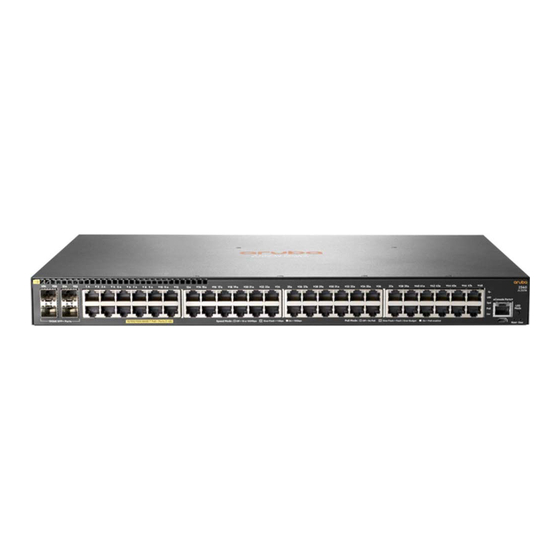
Table 1 Front of all the 2540 switches (continued) Label Description Aruba 2540 24G PoE+ 4SFP+ Switch (JL356A) Aruba 2540 48G PoE+ 4SFP+ Switch (JL357A) Figure 2 Example of the Front of the 2540 switches labels and descriptions Table 2 Front of the 2540 switches labels and descriptions... -
Page 8: Management Ports
These products also support optional network connectivity: Table 4 Optional network connectivity, speeds and technologies Transceiver form-factor and connector Speed Technology Cabling ("mini-GBIC") SFP+ connector Connector 100-FX Fiber 100 Mbps (multimode) 1000-T Copper RJ-45 (twisted-pair) 1000-SX Fiber (multimode) 1000-LX Fiber (multimode 1000 Mbps or single mode) 1000-LH... - Page 9 Figure 3 Chassis LEDs for the 2540 switches Table 5 Switch chassis LEDs Label Description Switch port LEDs Global status LED Unit identification LED Speed LED PoE LED* LED Mode button Usr LED * PoE Mode LED is present only on switch models that support PoE. Table 6 Front of switch status and mode LED behavior Switch LEDs Function...
- Page 10 Table 6 Front of switch status and mode LED behavior (continued) Switch LEDs Function State Meaning UID (Unit Identification) The Unit Identification LED On or slow flash* The "chassislocate" is used to help you to identify command allows you to blink a particular unit in a rack or or turn on the LED for a collection of products.
-
Page 11: Led Mode Select Button And Indicator Leds
Table 7 Port LEDs and mode behavior (continued) Switch LEDs Function State/Mode Meaning Activity/Link mode selected Port LEDs are displaying link Half-bright green The port is enabled and status and network activity receiving a link indication information simultaneously. from the connected device. Activity/Link mode is the Activity flicker green The percentage of time that... -
Page 12: Reset And Clear Buttons
Reset and Clear buttons The Reset and Clear buttons are recessed from the front panel (to protect them from being pushed accidentally) and are accessible through small holes on the top of the front panel. Use pointed objects, such as unbent paper clips, to push them. The Reset and Clear buttons are used singly or in combination, as follows: To accomplish this: Do this:... -
Page 13: Power Connector
Power connector The 2540 switches do not have a power switch; they are powered on when connected to an active AC power source. The switches automatically adjust to any voltage between 100-127 and 200-240 volts and either 50 or 60 Hz. There are no voltage range settings required. Switch features The features of the 2540 Switches include: •... - Page 14 • To download product updates, go to either of the following: ◦ Hewlett Packard Enterprise Support Center Get connected with updates page: www.hpe.com/support/e-updates ◦ HPE Networking Software: www.hpe.com/networking/software ◦ To view and update your entitlements, and to link your contracts and warranties with your profile, go to the Hewlett Packard Enterprise Support Center More Information on Access to Support Materials page: www.hpe.com/support/AccessToSupportMaterials...
-
Page 15: Installing The Switch
Hewlett Packard Enterprise representative. NOTE: If an Aruba 2540 switch is to be shipped in a rack, it can be mounted and shipped in a Hewlett Packard Enterprise 10K rack using the HPE X410 Universal Rack Mounting Kit (J9583A). -
Page 16: Installation Procedures
Installation procedures Summary 1. Prepare the installation site (“1. Prepare the installation site” (page 17)). Ensure the physical environment into which you will be installing the switch is properly prepared, including having the correct network cabling ready to connect to the switch and having an appropriate location for the switch. -
Page 17: Installation Precautions
Installation precautions WARNING! • The rack or cabinet should be adequately secured to prevent it from becoming unstable and/ or falling over. • Devices installed in a rack or cabinet should be mounted as low as possible, with the heaviest devices at the bottom and progressively lighter devices installed above. -
Page 18: Verify The Switch Passes Self Test
1. Connect the power cord supplied with the switch to the power connector on the back of the switch, and then into a properly grounded electrical outlet. Figure 5 Connecting the power cord on the Aruba 2540 switches NOTE: The 2540 switches do not have a power switch. They are powered on when the power cord is connected to the switch and to a power source. -
Page 19: Led Behavior
NOTE: If an Aruba 2540 switch is to be shipped in a rack, it can be mounted and shipped in a Hewlett Packard Enterprise 10K rack using the HPE X410 Universal Rack Mounting Kit (J9583A). Additionally, it can also be mounted in any four post rack using the HPE X410 Universal Rack Mounting Kit (J9583A). - Page 20 WARNING! For safe operation, please read the mounting precautions in “Installation precautions” (page 17), before mounting a switch. EQUIPMENT CABINET NOTE: The 12-24 screws supplied with the switch are the correct threading for standard EIA/TIA open 19-inch racks. If installing the switch in an equipment cabinet such as a server cabinet, use the clips and screws that came with the cabinet in place of the 12- 24 screws that are supplied with the switch.
-
Page 21: Horizontal Surface Mount Option
Figure 8 Mounting the 2540 switches in a rack Horizontal surface mount option: Place the switch on a table or other horizontal surface. The switch comes with rubber feet in the accessory kit that can be used to help keep the switch from sliding on the surface. Attach the rubber feet to the four corners on the bottom of the switch within the embossed angled lines. -
Page 22: Installing Transceivers
Installing transceivers: Hold the transceiver by its sides and gently insert it into either of the slots on the switch until it clicks into place. When a transceiver is inserted the switch authenticates it. This can take 1-3 seconds, with the worst case being 5 seconds. If the transceiver is removed before the authentication completes a self test failure will be reported. -
Page 23: Optional) Connect A Management Console
Figure 11 Connecting the power cord 2. Re-check the LEDs during self test. See “LED Behavior” (page 19). 3. Use the included cable tie to secure the power cord to the switch. Figure 12 Using the cable tie on the 2540 switches 6. -
Page 24: Terminal Configuration
There is also the option of using a USB cable (not supplied) to connect the switch’s Micro USB Console Port to a PC. To use the USB Console Port, you must first download a USB driver to the PC. See the Note on page 24 for more information. -
Page 25: Console Cable Pinouts
To use the USB Console Port, you must first download a USB driver to the PC. See the Note on page 24 for more information. Figure 13 Connecting a console cable 2. Turn on the terminal or PC’s power and, if using a PC, start the PC terminal program. 3. -
Page 26: Connect The Network Cables
Table 10 Mapping of RJ-45 to DB-9 (Continued) RJ-45 (Signal reference from Chassis) DB-9 (Signal reference from PC) Reserved 7. Connect the network cables Connect the network cables, described under “Cabling Infrastructure” (“1. Prepare the installation site” (page 17)), from the network devices or your patch panels to the fixed RJ-45 ports on the switch or to any SFPs you have installed in the switch. - Page 27 Figure 16 Connecting cable to a transceiver 7. Connect the network cables...
-
Page 28: Sample Network Topologies
Sample network topologies This section shows a few sample network topologies in which the Aruba 2540 switches are implemented. For more topology information, visit the product’s website at www.hpe.com/ networking/support. As a desktop switch implementing PoE The switch is designed to be used primarily as a desktop switch to which end nodes, printers and other peripherals, and servers are directly connected, as shown in the following illustration. -
Page 29: As A Segment Switch Implementing Poe
As a segment switch implementing PoE Figure 18 Segment network configuration with PoE switches The Aruba 2540 switch also works well as a segment switch. That is, with its high performance, it can be used for interconnecting network segments—simply connect the network devices that form those segments to the switch, or you can also connect other switches. -
Page 30: Getting Started With Switch Configuration
3 Getting started with switch configuration This chapter is a guide for using the console Switch Setup screen to quickly assign an IP (Internet Protocol) address and subnet mask to the switch, set a Manager password, and, optionally, configure other basic features. For more information on using the switch console, see the Basic Operation Guide and the Management and Configuration Guide for your switch at www.hpe.com/networking/... - Page 31 Figure 19 Example console setup screen Aruba-2540-24G-PoEP-4SFPP 6-Aug-2016 8:23:16 ==========================- CONSOLE - MANAGER MODE -========================== Switch Setup System Name : Aruba-2540-24G-4SFPP System Contact : Manager Password : **************** Confirm Password : **************** Logon Default : CLI Time Zone [0] : 0 Community Name : public Spanning Tree Enabled [No] : No Default Gateway :...
-
Page 32: Where To Go From Here
Table 11 Default parameters (continued) Parameter Default IP Config (DHCP/ DHCP/Bootp Set to Manual unless a DHCP/Bootp server is used on your network Bootp) to configure IP addressing. IP Address xxx.xxx.xxx.xxx Recommended; If you set IP Config to Manual, then enter an IP address compatible with your network. -
Page 33: Starting A Web Browser Session
Starting a web browser session The Aruba 2540 switches can be managed through a graphical interface that you can access from any PC or workstation on the network by running your web browser and typing in the switch’s IP address as the URL. No additional software installation is required to make this interface available;... -
Page 34: Troubleshooting
• Restoring the factory default configuration (see “Restoring the factory default configuration” (page 39)) • Downloading new software to the Aruba 2540 switches (see “Downloading new switch software” (page 40)) • Hewlett Packard Enterprise Customer Support Services (see “Hewlett Packard Enterprise Customer Support Services”... -
Page 35: Diagnosing With The Leds
information” (page 43) for pinouts and correct cable wiring. A category 5 cable tester is a recommended tool for every 100BASE-TX and 1000BASE-T network installation. • Improper network topologies. It is important to make sure you have a valid network topology. Common topology faults include excessive cable length and excessive repeater delays between end nodes. -
Page 36: Diagnostic Tips
Table 12 LED error indicators (continued) LED Pattern Indicating Problems Global Status Port LED Diagnostic Tip Solid green On, but the port is not communicating The flashing behavior is an on/off cycle once every 1.6 seconds, approximately. Diagnostic tips: Problem Solution The switch is not plugged Verify the power cord is plugged into an active power source and to the switch. -
Page 37: Led Patterns For Poe Troubleshooting
Problem Solution The network connection Try the following procedures: is not working properly. For the indicated port, verify that both ends of the cabling, at the switch and the connected device, are connected properly. Verify the connected device and switch are both powered on and operating correctly. Verify you have used the correct cable type for the connection: For twisted-pair connections to the fixed 10/100/1000 ports, if the port is configured to “Auto”... -
Page 38: Diagnostic Tips
If a hardware failure is confirmed, replace the switch. power delivery has failed. Proactive networking The Aruba 2540 switch has built-in management capabilities that proactively help you manage your network including: • finding and helping you fix the most common network error conditions (for example, faulty network cabling, and non-standard network topologies) •... -
Page 39: Checking The Switch Leds
• reboot the switch via the management console’s boot system command. Power cycling the switch and pressing the Reset button both cause the switch to perform its power- on self test. These reset processes also cause any network traffic counters to be reset to zero, and cause the System Up Time timer to reset to zero. -
Page 40: Downloading New Switch Software
event log, resets the network counters to zero, performs a complete self test, and reboots the switch into its factory default configuration including deleting the IP address, if one is configured. NOTE: This process removes all switch configuration changes that you have made from the factory default settings. -
Page 41: Specifications
Aruba 2540 48G 4SFP+ Switch (JL355A) 200-240 volts 0.6 A 100-127 volts 4.9 A 50/60 Hz Aruba 2540 24G PoE+ 4SFP+ Switch (JL356A) 200-240 volts 2.4 A 100-127 volts 5.1 A 50/60 Hz Aruba 2540 48G PoE+ 4SFP+ Switch (JL357A) 200-240 volts 2.5 A... -
Page 42: Safety
Aruba 2540 24G PoE+ 4SFP+ Switch (JL356A) Sound Power (LWAd) 5.4 Bel Sound Pressure (LpAm) (Bystander) 40.6 dB Aruba 2540 48G PoE+ 4SFP+ Switch (JL357A) Sound Power (LWAd) 5.6 Bel Sound Pressure (LpAm) (Bystander) 41.7 dB Safety • EN60950-1:2006+A11:2009+A1:2010+A12:2011+A2:2013 •... -
Page 43: Cabling And Technology Information
6 Cabling and technology information This appendix includes switch connector information and network cable information for cables that should be used with the Hewlett Packard Enterprise switches. NOTE: Incorrectly wired cabling is a common cause of problems for LAN communications. Hewlett Packard Enterprise recommends that you work with a qualified LAN cable installer for assistance with your cabling requirements. -
Page 44: Technology Distance Specifications
Technology distance specifications Table 16 Technology distance specifications Technology Supported cable type Multimode fiber Supported distances modal bandwidth 100-FX multimode fiber up to 2,000 meters twisted-pair copper up to 100 meters 1000-T 1000-SX multimode fiber 160 MHz*km 2 - 220 meters 200 MHz*km 2 - 275 meters 400 MHz*km... -
Page 45: Installing The Patch Cord
MDI-X ports, the Aruba 2540 Switch port automatically operates as an MDI port. If you connect it to an end node, such as a server or PC, which typically have MDI ports, the Aruba 2540 Switch port operates as an MDI-X port. In all cases, you can use standard straight-through cables or crossover cables. -
Page 46: Other Wiring Rules
Other wiring rules: • All twisted-pair wires used for 10 Mbps, and 100 Mbps operation must be twisted through the entire length of the cable. The wiring sequence must conform to EIA/TIA 568-B (not USOC). See “Twisted-Pair Cable Pin Assignments” later in this appendix for a listing of the signals used on each pin. -
Page 47: Pin Assignments
Pin assignments Switch end (MDI-X) Computer, transceiver, or other end Signal Pins Pins Signal receive + transmit + receive - transmit - transmit + receive + transmit - receive - Crossover twisted-pair cable for 10 Mbps or 100 Mbps network connection The Auto-MDIX operation of the 10/100 ports on the switch also allows you to use crossover cables for all network connections, to PCs, servers or other end nodes, or to hubs or other switches. -
Page 48: Cable Diagram
Cable diagram NOTE: Pins 1 and 2 on connector “A” must be wired as a twisted pair to pins 1 and 2 on connector “B”. Pins 3 and 6 on connector “A” must be wired as a twisted pair to pins 3 and 6 on connector “B”. Pins 4 and 5 on connector “A”... -
Page 49: Support And Other Resources
7 Support and other resources Accessing Hewlett Packard Enterprise support • For live assistance, go to the Contact Hewlett Packard Enterprise Worldwide Support website: www.hpe.com/assistance • To access documentation and support services, go to the Hewlett Packard Enterprise Support Center website: www.hpe.com/support/hpesc Information to collect •... -
Page 50: Websites
www.hpe.com/support/e-updates • To view and update your entitlements, and to link your contracts, Care Packs, and warranties with your profile, go to the Hewlett Packard Enterprise Support Center More Information on Access to HP Support Materials page: www.hpe.com/support/AccessToSupportMaterials IMPORTANT: Access to some updates might require product entitlement when accessed through the Hewlett Packard Enterprise Support Center. -
Page 51: Documentation Feedback
Documentation feedback Hewlett Packard Enterprise is committed to providing documentation that meets your needs. To help us improve the documentation, send any errors, suggestions, or comments to DocumentationFeedback (docsfeedback@hpe.com). When submitting your feedback, include the document title, part number, edition, and publication date located on the front cover of the document. -
Page 52: Warranty And Regulatory Information
8 Warranty and regulatory information For important safety, environmental, and regulatory information, see Safety and Compliance Information for Server, Storage, Power, Networking, and Rack Products, available at www.hpe.com/support/Safety-Compliance-EnterpriseProducts. Warranty information HPE networking products www.hpe.com/support/Networking-Warranties Regulatory information Turkey RoHS material content declaration Türkiye Cumhuriyeti: EEE Yönetmeliğine Uygundur. - Page 53 Index Numerics Switch Setup screen 30 connecting the switch to a power source 22 1000Base-BX 44 console fiber-optic cable specifications 44 checking messages during troubleshooting 39 1000Base-LH 44 displaying the CLI prompt 25 fiber-optic cable specifications 44 features 23 1000Base-T how to connect in-band 24 1000Base-T how to connect out-of-band 23...
- Page 54 precautions 17 diagnostics with 38 site preparation 17 IP address rack configuring 31 mounting precautions 17 IP telephones 28 Reset button restoring factory default configuration 40 LEDs resetting the switch checking during troubleshooting 39 factory default reset 39 error indications 35 troubleshooting procedure 38 link test 39 RJ-45 console pinouts 25...
- Page 55 checking the console messages 39 checking the LEDs 39 common network problems 34 connecting to fixed full-duplex devices 34 diagnostic tests 38 effects of improper topology 35 effects of non-standard cables 34 link test 39 Ping test 39 Proactive Network tools 38 restoring factory default configuration 39 testing connections to other devices 39 testing end-to-end communications 39...
Need help?
Do you have a question about the Aruba 2540 and is the answer not in the manual?
Questions and answers