Table of Contents
Advertisement
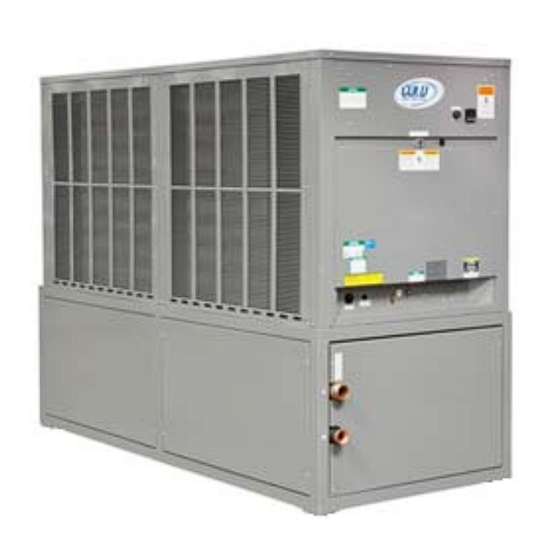
INSTALLATION, OPERATION, AND
MAINTENANCE INSTRUCTIONS
(ACWC-240-E model shown)
AIR-COOLED WATER CHILLERS
ACWC-120 through - 240 MODELS
Model#: ACWC-180-EM-DR-LT-0-5
Marrone & Co., Inc.
2730 Maximilian Dr., Houston, Texas 77032 • Phone (800) 473-9178, (281) 227-8400
Fax (800) 473-9175, (281) 227-8404 • www.waterchillers.com
Advertisement
Table of Contents

Related Manuals for Cold Shot Chillers ACWC-180-EM-DR-LT-0-5


Summary of Contents for Cold Shot Chillers ACWC-180-EM-DR-LT-0-5
- Page 1 INSTALLATION, OPERATION, AND MAINTENANCE INSTRUCTIONS (ACWC-240-E model shown) AIR-COOLED WATER CHILLERS ACWC-120 through - 240 MODELS Model#: ACWC-180-EM-DR-LT-0-5 Marrone & Co., Inc. 2730 Maximilian Dr., Houston, Texas 77032 • Phone (800) 473-9178, (281) 227-8400 Fax (800) 473-9175, (281) 227-8404 • www.waterchillers.com...
-
Page 2: Table Of Contents
MODEL NUMBER NOMENCLATURE Example Model#: ACWC Position: Position-Description 1. Model Type: ACWC=AirCooledWaterChiller, WCWC=WaterCooledWaterChiller, etc. 2. Nominal Capacity in kBtu/hr 3. Series System: various 4. Flow Design: (_=Portable, ST=Stationary, RF=ReverseFlow, EXCH=HeatExchanger, DP=DualPump, DR=DualReturn) 5. Leaving Fluid Temperature (_=Standard, LT=LowTemperature-specify lowest temperature in °F) 6. -
Page 3: Important
Inspect carton’s exterior for evidence of rough handling in shipment. Carefully remove protective wrap and all banding to uncrate, for inspection; if damage is found, report immediately to the transportation agency and Cold Shot Chillers. Provide a report and photographs (highly recommended), if possible. -
Page 4: Installation
II. INSTALLATION A. MOVEMENT/RIGGING 1. The preferred method for movement of the chiller while on the pallet is with forklift or pallet jack. 2. For rigging, overhead rigging with spreader bars above the unit is preferred. Protect unit from being crushed. CAUTION! All panels must be in place when rigging. -
Page 5: Split Systems (Remote Condenser Or Condensing Unit)
National Electrical Code (NEC), Section 440-14. b) Verify electrical power on the Cold Shot Chillers label plate with actual voltage. c) Connect line power supply to terminal block or as noted in machine; typically, connect power leads to terminals L1, L2 and L3 on compressor contactor. -
Page 6: Freeze Protection
FIRST CONTACTING COLD SHOT CHILLERS. ANY MODIFICATIONS OF THE CHILLER SYSTEM FROM THE MANUFACTURER’S DESIGN WILL REQUIRE PRIOR WRITTEN APPROVAL FROM COLD SHOT CHILLERS, OTHERWISE ALL WARRANTIES WILL BECOME VOID. G. GLYCOL 1. Glycol and water mixtures are common methods to change a fluid’s freezing point but may reduce the cooling performance of the chiller. -
Page 7: Performance
3. Glycol concentrations affect cooling performance. As the temperature reduces, the fluid becomes thicker which may reduce heat transfer capabilities and reduces the circulating pump performance. IMPORTANT!! DAMAGE CAUSED BY FLUIDS WITH INADEQUATE FREEZE POINT PROTECTION IS NOT CONSIDERED FAILURE DUE TO PRODUCT OR WORKMANSHIP AND IS NOT COVERED BY WARRANTY. -
Page 8: Pre-Startup
III. PRE-STARTUP 1. STARTUP CHECKLIST - Review and use. (Typically located at end of this manual.) 2. COMPRESSOR MOUNTS a) As shipped, the compressor(s) is held down by mounting bolts with vibration rubber grommets. b) Verify bolts are tight to base and that the compressor is able to move on the rubber grommets. (1) Single Compressor units: Verify that the shipping spacers (if installed) are removed from between the compressor bottom (or compressor plate) and the base of the unit. -
Page 9: Startup
IV. STARTUP 1. Verify installation is complete and all Pre-Startup steps are completed. 2. STARTUP CHECKLIST - Review and use. (Typically, located at end of this manual) 3. Attach refrigerant gauges to the appropriate service ports. 4. PUMP ONLY: Turn switch to Pump Only (or use local system pump) and operate for at least 15 minutes. -
Page 10: System Components: (See Your Chiller's Specification For Details.)
(4) Returning fluid temperature should not exceed 80°F on standard units or the chiller will cycle off on high head pressure and not run. Should this occur, allow water to cool down and restarting chiller once water is below 80°F. d) SUPERHEAT: Verify or set the expansion valve (TXV) superheat to approximately 10 to 12°F immediately downstream of the TXV or approximately 12 to 14°F as measured 6 to 12 inches from the compressor on the suction line. - Page 11 6. FILTER/DRIER a) Monitors the pressure of the refrigerant For system cleanliness and moisture capture. suction line and will automatically open Every unit will have a filter drier factory when the pressure drops below the set installed. point and will automatically reset when 7.
- Page 12 21. REMOTE OPERATION CONTROLS (OPTION) levels depending on design such as: Various designs (contact Cold Shot Chillers for a) Safety – to stop the operation of options) something such as the chiller or 22.
-
Page 13: Maintenance (Basic Guide)
If any questions regarding the equipment, please contact Cold Shot Chillers for assistance. NOTE: Not performing the following will cause early unit failure and considered abuse which is not covered by warranty. - Page 14 Refer to the necessary to adjust the offset in the controller chiller’s electrical schematics or the motor parameters. Contact Cold Shot Chillers for nameplate for proper amp draws. Log assistance. readings.
-
Page 15: Troubleshooting (Basic Guide)
VII. TROUBLESHOOTING (BASIC GUIDE) • The Troubleshooting Guide below is to be used as a guide only. All work should be performed by a trained technician and only with proper understanding of the system. Contact manufacturer for further assistance. • Prior to resetting any safety devices, ensure that the issue is resolved or use care in operating the system until the cause is determined. - Page 16 SYMPTOM AND PROBABLE CAUSE PROBABLE REMEDY UNIT OPERATES TOO LONG OR CONTINUOUSLY 9. Low refrigerant charge. 9. Add refrigerant. 10. Control contacts fused. 10. Replace control. 11. Air in system. 11. Purge and evacuate system. SYSTEM IS NOISY 1. Piping vibration. 1.
- Page 17 7. Motor defective. 7. Check motor winding for open or short. Replace motor/pump, if necessary. VOLTAGE IMBALANCE 1. Voltage Imbalance over 2% - Incoming Power 1. Main Incoming Voltage – - (Check Voltage at front and backside of each - A voltage imbalance may be an indication of loose contactor during operation.) wires/cable connections or faulty contactors.
-
Page 18: Appendix
VIII. APPENDIX A. Temperature Controller Information B. Technical Specification C. Physical/Installation Drawings D. Electrical Drawings Component Technical (Pump, options, etc, when available) Parts Warranty G. Labor Warranty (if included) H. Startup Checklist - 18 - MNL_Standard-Basic_ACWC-24to240-E-(IN PROGRESS)_(0815).docx... -
Page 19: Sequence Of Operation
If the value is above or below the limits of the controller, the SV will go to the closest limit value. Do not adjust any settings other that SV without contacting Cold Shot Chillers. IMPORTANT! Continuous restarting of the system with a fault is considered abuse and will void all warranties. -
Page 20: Fault Codes
(1) If temperature is decreasing, then the second compressor will not start. (a) The High Deviation fault condition is bypassed as long as temperature is decreasing. (2) If temperature is increasing, then the second compressor will start. (a) If the temperature is above the High Deviation and temperature is increasing, then a timer starts, which if temperature does not lower within the time, then a High Deviation fault will occur. - Page 21 Loss of Communications between Temperature Controller and PLC 9 8 2 0 Loss of Communications between Temperature Controller and Temperature Sensor/Thermocouple If further assistance is needed regarding the Contact Cold Shot Chillers with any concerns or issues, as needed. Example of Temperatures of Operation Typical Values...
- Page 22 DTB4848 Series Temperature Controller Settings ABA Setup Initial Settings Mode Value Set Codes ACTUAL SETTINGS Code Description CnPt Input Type tPUn Temperature Unit tP-H Scale Range Upper Limit (or default) 999.9 tP-L Scale Range Lower Limit (or default) -99.9 CtRL Control Mode onoF S-HC...
- Page 23 Liquid Flow Switch PT # LIFS-000-100-0-1 2730 Maximilian Drive, Houston, Texas 77032 Phone (800) 473-9178, (281) 227-8400 Fax (800) 473- 9175, (281) 227-8404 www.waterchillers.com...
- Page 24 - No underline indicates normally open (NO) contact, Underline indicates normally closed (NC) contact. Power Supply Run Capacitor 7. All intellectual property, including designs and programming logic are the property of Cold Shot Chillers and is not to be Selector Switch (Pump/Off/Cooling) copied or used without permission from Cold Shot Chillers.
- Page 25 P266 Series Single-Phase Condenser Fan Speed Control Abbreviated Version Installation Instructions P266xxx-x Part No. 24-7664-2705, Rev. B Issued April 29, 2009 Supersedes January 21, 2009 Application IMPORTANT: Use this P266 Single-Phase Condenser Fan Speed Control only as an operating control. Where failure or malfunction of the P266 fan speed control could lead to personal injury or property damage to the controlled equipment or other property, additional precautions must be...
-
Page 26: Technical Specifications
Refer to the P499 Series Electronic Pressure P266 Electronic Pressure Transducers P266 controls are designed to reference either one or Transducers Product/Technical Bulletin (LIT-12011190) for information on installing P266 transducers. two Johnson Controls P266 Electronic Pressure Transducers to monitor condenser pressure. Table 3: P266SNR Electronic Pressure Transducers P266 transducers are specialized versions of the... - Page 27 TECHNICAL SPECIFICATION Model: ACWC-180-EM-DR Description: Two stage portable air-cooled water chiller system. To provide approximately 180,000 Btu/hr of cooling capacity with a leaving fluid temperature of 50°F with an ambient air temperature of 95°F. CAPACITY 180,000 BTU /HR ±5% AT 50° LCWT / 95°F AMBIENT COMPRESSOR / REFRIGERANT TANDEM HERMETIC SCROLL / R410A CONDENSER FANS / AIRFLOW...
- Page 28 • Reference the chiller serial number when ordering parts for specific supplied pump. COLD SHOT CHILLERS / Marrone & Co., Inc. 2730 Maximilian Drive, Houston, Texas 77032 • Phone (800) 473-9178, (281) 227-8400 Fax (800) 473- 9175, (281) 227-8404 • www.waterchillers.com...
- Page 29 8' clear air space above the unit Condenser Fans - Dimensions are approximate. (inches) - Casters (Optional) - All specifications subject to change without notice. COLD SHOT CHILLERS SIZE VIEW DWG NO INSTALLATION DRAWING Front-Back-Left-Right-Top...
- Page 30 Tandem Compressor Models only Compressor Low Pressure Switch Flow Safety Thermostat Air Cooled Condenser Suction Service Valve Compressor Sensing Bulb Tube Suction Accumulator* External Low Side Additional Evaporator Service Fitting Fans* CHILLER Condenser Coils (Fluid System) Hot Gas Bypass Valve High Pressure (Optional) Sensing Bulb Tube...
- Page 31 (OUT) GLOBE VALVE (Optional) CHILLER DRAIN PUMP TEMPERATURE SENSOR (Temperature Controller) COLD SHOT CHILLERS SIZE FSCM NO DWG NO CHILL WATER CIRCUIT – TYPICAL ENGINEERING DRAWN E - “Portable - Dual Return with Globe Valve and Flow Switch” 05/2011 ISSUED...
- Page 32 6. Design, specifications, and components are subject to change without notice. Tank Level Switch – High 7. All intellectual property, including designs and programming logic are the property of Cold Shot Chillers and is not Tank Level Switch – Low FILE: DWG_Electrical-DeltaControl-SeriesA120_081915.vsd...
- Page 33 - No underline indicates normally open (NO) contact, Underline indicates normally closed (NC) contact. Power Supply Run Capacitor 7. All intellectual property, including designs and programming logic are the property of Cold Shot Chillers and is not to be Selector Switch (Pump/Off/Cooling) copied or used without permission from Cold Shot Chillers.
- Page 34 - No underline indicates normally open (NO) contact, Underline indicates normally closed (NC) contact. Power Supply Run Capacitor 7. All intellectual property, including designs and programming logic are the property of Cold Shot Chillers and is not to be Selector Switch (Pump/Off/Cooling) copied or used without permission from Cold Shot Chillers.
- Page 35 Notes...
- Page 36 MAINTENANCE RECORD DATE PROCEDURE PERFORMED...
- Page 37 TYPICAL START-UP CHECK LIST EQUIPMENT MODEL# SERIAL# OWNER NAME PHONE# ADDRESS CITY STATE INSTALLING CONTRACTOR PHONE# ADDRESS CITY STATE START-UP PERFORMED BY PHONE# * Designates Pre-Startup items. To be performed before Startup of system. 1. *Manual referred to for details on installation and startup (IMPORTANT). 2.
- Page 38 COMMENTS: __________________________________________________________________________________________________ __________________________________________________________________________________________________ __________________________________________________________________________________________________ __________________________________________________________________________________________________ __________________________________________________________________________________________________ __________________________________________________________________________________________________ __________________________________________________________________________________________________ __________________________________________________________________________________________________ __________________________________________________________________________________________________ __________________________________________________________________________________________________ __________________________________________________________________________________________________ __________________________________________________________________________________________________ __________________________________________________________________________________________________ __________________________________________________________________________________________________ __________________________________________________________________________________________________ __________________________________________________________________________________________________ __________________________________________________________________________________________________ __________________________________________________________________________________________________ SIGNATURES: START UP CUSTOMER TECHNICIAN ____________________________ REPRESENTATIVE _______________________ DATE _____________________________ DATE ________________________ Marrone & Co., Inc. 2730 Maximilian Drive, Houston, Texas 77032 • Phone (800) 473-9178, (281) 227-8400 Fax (800) 473- 9175, (281) 227-8404 •...
Need help?
Do you have a question about the ACWC-180-EM-DR-LT-0-5 and is the answer not in the manual?
Questions and answers
Motor and puma is neceser
The Cold Shot Chillers ACWC-180-EM-DR-LT-0-5 requires a 3-Hp, 3-phase (3Ø) motor with an ODP (Open Drip Proof) enclosure.
This answer is automatically generated
I need pump and motor
The manual mentions that the pump base is not supplied with footed motors and advises referencing the chiller serial number when ordering parts for the specific supplied pump. However, it does not specify the exact pump and motor models compatible with the Cold Shot Chillers ACWC-180-EM-DR-LT-0-5.
This answer is automatically generated