Table of Contents
Advertisement
Quick Links
1250 2D/3D/3DV
Wheel Balancers
See
¨Balancing Your
First Tire
on page 1.
1601 J. P. Hennessy Drive, LaVergne, TN USA 37086-3565 615/641-7533 800/688-6359 www.ammcoats.com
HENNESSY INDUSTRIES INC. Manufacturer of AMMCO
Installation Instructions
Operating Instructions
Safety Instructions
Maintenance Instructions
READ these instructions before placing unit in
service KEEP these and other materials delivered
with the unit in a binder near the machine for
ease of reference by supervisors and operators.
, COATS
and BADA
Automotive Service Equipment and Tools.
®
®
®
®
Manual Part No.: 8114307 13
Revision:
6/13
Advertisement
Table of Contents

Summary of Contents for HENNESSY INDUSTRIES coats 1250 2D
- Page 1 1601 J. P. Hennessy Drive, LaVergne, TN USA 37086-3565 615/641-7533 800/688-6359 www.ammcoats.com Manual Part No.: 8114307 13 HENNESSY INDUSTRIES INC. Manufacturer of AMMCO , COATS and BADA Automotive Service Equipment and Tools.
- Page 2 IMPORTANT SAFETY INSTRUCTIONS READ ALL INSTRUCTIONS 10. Wear proper clothing. Safety toe, non-slip 1. Eye and face protection recommendations: footwear and protective hair covering to contain “ Protective eye and face equipment is required to hair is recommended. Do not wear jewelry, loose be used where there is a reasonable probability of clothing, neckties, or gloves when operating the injury that can be prevented by the use of such...
-
Page 3: Operator Protective Equipment
Safety Owner’ s Responsibility Definitions of Hazard Levels To maintain machine and user safety, the responsibil- Identify the hazard levels used in this manual with the ity of the owner is to read and follow these instruc- following definitions and signal words: tions: DANGER •... -
Page 4: Safety Notices And Decals
For additional copies of either, or further information, con- tact: Hennessy Industries, Inc. CAUTION 1601 J.P. Hennessy Drive LaVergne, TN 37086-3565 (615) 641-7533 or (800) 688-6359 Use of controls, adjustments or perform- www.ammcoats.com... -
Page 5: Standard Safety Devices
Standard Safety Devices • STOP key for stopping the wheel under emergency conditions. • A hood guard of high impact plastic that is designed to prevent the counterweights from flying out in any direction except towards the floor. • A hood switch interlock system that prevents the machine from starting if the guard is not lowered and stops the wheel whenever the guard is raised. -
Page 6: Table Of Contents
Table of Contents Installation Instructions ....20 Important Safety Instructions ... . .ii Receiving ....... .20 Owner’... -
Page 7: Balancing Your First Tire
¨Balancing Your First Tire 1. Turn the machine OFF then ON 8. Inboard center bar blinks. (resets machine). Note: If an inboard corrective weight is not Note: The machine wakes up using standard clip- required, the wheel will stop at the outboard on wheel weight locations (Clip 1 &... -
Page 8: Principle Operating Parts
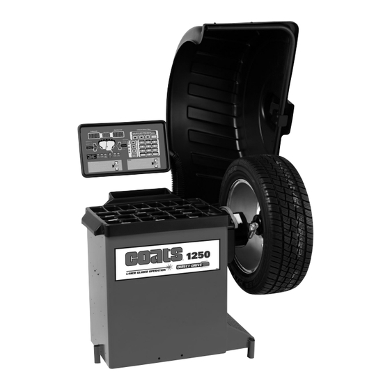
Principle Operating Parts 1250 Non-video Shown Do It Now! Now is a good time to fill out the Owner’ s Registry Card. 2 • Important: Always read and follow the information box instructions. -
Page 9: Know Your Unit
Know Your Unit Power Switch Compare this illustration with the unit before placing The ON/OFF decal (figure 4) indicates the ON/OFF it into service. Maximum performance and safety will switch location at the back of the balancer. be obtained only when all persons using the unit are fully trained in its parts and operation. - Page 10 When prompted by balance r instructions, use the off- Note: The T2 - Tape Direct Select™ Weight position is set arm (figure 6A) to enter A & D measurements auto- the only mode that requires the A2 & D2 dimension matically.
-
Page 11: Using The Laser Locator
Using The Line Laser If the T2 - Tape (hidden Tape-A-Weight ) location is ® selected, use the line laser to align the offset arm with the laser locator dot (figures 8 & 7B); entering A2 & D2 measurements automatically. Grasp arm at the line laser and pull out and up to the wheel flange (figure 6B). -
Page 12: Laser Guided Operation™ System
Laser Guided Operation™ System 9. Respin tire/wheel to check balance. The operator must select T2 - Tape Laser Locator to activate the Laser Guided Operation™ feature, see page 8 for the button selection. This Direct Select™ weight location is used when placing hidden adhesive weights at the inner area of the wheel and is the required weight location selection for the Behind Spoke mode. -
Page 13: Setting Wheel Dimensions (Dim)
Setting Wheel Dimensions (DIM) Basic Wheel Data Entry 1. Select the Clip 1 or T1 -Tape weight location and Before a wheel can be balanced, wheel dimensions the T3 - Tape or Clip 2 weight location. must be entered into the computer. 2. -
Page 14: Control Panel Function And Review
Control Panel Function and Review If you select/press … Then … a Direct Select Weight key (Clip 1, on the Wheel Cross-section diagram, the activated weight location illumi- T1-Tape, Patch Static, T2-Tape, T3- nates. Tape, or Clip 2) the T2-Tape key the laser indicator illuminates;... - Page 15 Figure 14A - 1250 Video Control Panel Feature Reference Figure 14B - 1250 Non-video Control Panel Feature Reference Important: Always read and follow the information box instructions. • 9...
-
Page 16: Control Panel Quick Reference
Control Panel Quick Reference Mode Indicators Screen Saver Mode (Video) The mode indicator will show whether the mode is activated. Modes are as follows: By default, the 1250 video version wheel balancer is shipped with the screen saver mode set to dim the dis- Operator A or Operator B - when illuminated, indi- play back light after a period of inactivity (20 minutes). -
Page 17: Direct Select™ Weight Placement Location
Direct Select™ Weight Placement Location Information Box Before spinning the wheel, use direct select to indi- Displays A, W, and D values, functions, and instruc- cate weight placement locations as follows: tions for the operator. Error messages will also be shown in this display. -
Page 18: Balancing Using Direct Select
Balancing Using Direct Select™ Static Balancing Choose a static balance for wheel assemblies that A variety of wheel configurations can be balanced are not possible to balance dynamically or for narrow using this wheel balancer. Read through this section, it wheels. - Page 19 Begin by following the Laser Guided Operation™ pro- Patch Weight Balance - Use a static patch weight bal- cedure, steps 1 through 4 on page 6. ance when there is a very large unbalance in a tire assembly or if a very large tire has a large unbalance. A 1.
-
Page 20: Mounting Wheel On Spindle Shaft
Mounting Wheel on Spindle Standard Back Cone Mounting Shaft Most original equipment and steel wheels can be mounted properly using this method. The wheel is centered on a cone from the inner side of the hub. CAUTION 1. Place the cone spring onto the shaft with the large end towards the faceplate. -
Page 21: Standard Front Cone Mounting
Standard Front Cone Mounting Alternate Mounting A wheel should be centered by the outer side of the If the wheel has a protruding outer hub which will not hub only when the inner surface will not provide an permit the use of the pressure cup, or the cup will not accurate surface to center on. -
Page 22: Match Balance (Optimization)
Match Balance (Optimization) 5. Using a tire changer, rotate the tire 180 degrees on the rim. The Match Balance (Tire/Rim Weight Optimization) 6. Remount wheel assembly on the balancer. Press 2 procedure is used to determine the best mating of tire and rim that will result in the least amount of total on the control panel;... -
Page 23: Calibration
Calibration Important: It is critical that the inner weight be placed accurately to achieve proper calibration. If the Machine Calibration calibration weight is not moved from the outside Important: Be sure to use the correct calibration flange directly across to the inside flange, an inner weight amount: a 4-ounce calibration weight in ounce weight placement error will occur. -
Page 24: Maintenance Instructions
3. Bring the tip edge of the arm precisely to the outer buildup will cause inaccurate balancing and premature edge of the faceplate and hold it there while pressing wear. Clean these items at least once a day with a the NEXT key. -
Page 25: Diagnostic Procedures
Diagnostic Procedures Error Messages - One of the following error mes- sages, shown in the information box display, may After Balance Vibration Problems appear indicating a problem with the balancer. If vibration is still present after balancing the wheels Note: Always EXIT error message and repeat func- and driving the vehicle on smooth pavement, remove tion to see if error is eliminated. - Page 26 Installation Instructions Setup Receiving CAUTION The shipment should be thoroughly inspected as soon as it is received. The signed bill of lading is Do not use the control panel, control panel acknowledgement, for the carrier, of receipt in good base, accessory storage, faceplate, hood or condition of the shipment covered by our invoice.
- Page 27 Specifications Features Wheel Diameter Range • Automatic Data Entry for Offset and Diameter - 8 - 30 inches Manual Entry Backup on all Parameters • Static-on-Screen™ Wheel Width Range 2 - 20 inches • Four Fixed Function Keys, Seven Program Keys for user Friendly Operation Maximum Outside Tire Diameter Up to 44 inches...
- Page 28 8114307 13 6/13 © Copyright 2005 Hennessy Industries and COATS All Rights Reserved Printed in USA...
Need help?
Do you have a question about the coats 1250 2D and is the answer not in the manual?
Questions and answers