
Related Manuals for Cheetah 64NE

Summary of Contents for Cheetah 64NE
- Page 1 ANUAL 64NE, 64XE, & 64WE IDEO ATRIX WITCHERS Publication: 81-9059-0577-0, Rev. E www.PESA.com July 2012...
- Page 2 81-9059-0577-0 Rev. E Thank You !! for purchasing your new Cheetah signal routing equipment from PESA. We appreciate your confidence in our products. PESA produces quality, state-of-the-art equipment designed to deliver our users the highest degree of performance, dependability and versatility available anywhere.
-
Page 3: Table Of Contents
HEETAH HASSIS EVEL ODES TROBES 5.5.1 Cheetah 64NE Chassis Strobe Switch Location and Settings.........5-4 5.5.2 Cheetah 64XE and 64WE Chassis Strobe Switches Location and Settings.....5-5 5.5.3 Cheetah 64 Series Chassis Strobe Switch Functions............5-6 64NE, 64XE, 64WE C ..5-7 HEETAH HASSIS... - Page 4 ................8-1 HEETAH ERIES OWER UPPLIES 8.1.1 Cheetah Series Power Supply Information..............8-1 8.1.2 Cheetah Series Chassis Power Supplies Locations and Allocations.......8-2 8.1.3 LED Indicators and Test Points..................8-3 8.1.4 +28V Test Points......................8-3 8.1.5 Installing the Power Supplies ..................8-4 8.1.6 Removing the Power Supplies..................8-4 ....................8-5...
- Page 5 MAINTENANCE AND REPAIR ................9-1 ......................9-1 AINTENANCE 9.1.1 Maintenance Overview....................9-1 9.1.2 Air Filter........................9-1 9.1.3 Fan Replacement Sequences..................9-2 9.1.4 Cheetah 64 Series Fan Replacements ................9-3 .....................9-4 ROUBLE SHOOTING 9.2.1 Troubleshooting Overview....................9-4 9.2.2 Subassembly LEDs .......................9-4 9.2.3 Unresolved Troubleshooting Problems .................9-9 ........................9-10 EPAIR 9.3.1...
- Page 6 TROBE WITCH OCATION AND ETTINGS 5-3 C 64NE, 64XE, 64WE C .....5-7 IGURE HEETAH HASSIS ATRIX ACKPLANE WITCHES 5-4 64NE, 64XE, 64WE C IGURE HASSIS YSTEM NTERFACE ONNECTOR OCATIONS AND ) ......................5-8 ESCRIPTIONS 5-5 C 64 S )......5-9 IGURE HEETAH...
- Page 7 64 S HEETAH ERIES ABLES 81-9059-0577-0 Rev. E IST OF ABLES 3-1 C 64 S .............3-2 ABLE HEETAH ERIES CTIVE OMPONENTS ATRIX 3-2 C 64 S ..........3-3 ABLE HEETAH ERIES HASSIS OMPONENT UMBERS 5-1 STROBE SWITCH FUNCTIONS ..................5-6 ABLE 6-1 AC P ......................6-4 ABLE OWER...
-
Page 8: Warning
VERVIEW This manual provides detailed instructions for the installation, operation, and maintenance of the PESA Cheetah Series Switchers. It is the responsibility of all personnel involved in the installation, operation, and maintenance of the equipment to know all the applicable safety regulations for the areas they will be working in. -
Page 9: Cheetah 64 Series Introduction
64WE) will accept analog matrix and I/O cards. Cheetah 64 series system configurations will allow partitioning for either all analog or all digital cards to reside in the same frame in blocks of 64x64 and 64x128. The 64NE, 64XE, and 64WE frames can be configured for either all digital or all analog. -
Page 10: Cheetah 64 Series Switchers Features
2.3.1 Cheetah 64 Series Switchers Features Overview All Cheetah 64 series (64NE, XE, and WE) video matrix switchers offer alarm support, switch confirmation, block checking, and power-out-of-range indicators. A key feature of the 64NE and 64WE switchers is the Matrix Watchdog™ redundant crosspoint (matrix) option. For critical routing requirements of live, on-air situations or other critical distribution facilities, a redundant crosspoint can be added to automatically swap over in case of failure. - Page 11 – C HEETAH ERIES WITCHERS HAPTER 81-9059-0577-0 Rev. E • Supported signal types: SD/HD/3G Multirate from 143Mbs up to 3.0Gbs SDI and ASI Composite Analog Video AES 75Ω Audio ASI/EBU • Compatible with SMPTE 259M, 292M, 372M and 424M TV standards •...
- Page 12 ERIES ONFIGURATION ATRIX VERVIEW This section includes a list of all of the major components for the Cheetah 64NE, 64XE, and 64WE Video Matrix Switchers chassis/frames (models). When discussing output options and expandable outputs, the meanings are as follows: •...
-
Page 13: Cheetah 64 Series Chassis Configurations
* = Matrix “Crosspoint” Card ** = Dependant upon configuration (64x64, 64x80, 64x96, 64x112, or 64x128) The basic configuration features of the three Cheetah Series models are as follows: • 64NE: non-expandable outputs, no output options, and redundant crosspoints (matrix cards). -
Page 14: Cheetah 64 Series Chassis Component Part Numbers
ERIES HAPTER 81-9059-0577-0 Rev. E 64 S HEETAH ERIES HASSIS OMPONENT UMBERS Refer to Table 3-2. 3-2 Cheetah 64 Series Chassis Component Part Numbers ABLE TANDARD AINFRAME OMPONENTS 81906526750 64NE Mainframe Assembly 81906526900 64WE Mainframe Assembly 81906526760 64XE Mainframe Assembly... -
Page 15: Table 3-2 Cheetah 64 Series Chassis Component Part Numbers
64 S – C HEETAH ERIES HAPTER 81-9059-0577-0 Rev. E Table 3-2 Cheetah 64 Series Chassis Component Part Numbers (Cont.) UTPUT ARDS 81906523150 Cheetah Output Combiner SD BNC 81906526250 Cheetah Output Combiner HD-MR BNC 81906524930 Cheetah Output Combiner Composite Video... -
Page 16: Cheetah 64Ne Frame Views
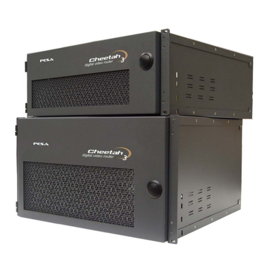
There are two chassis’ sizes that house the Cheetah 64 Series switchers, which are the 6RU and 4RU chassis. The 64XE and the 64WE are housed in a 6RU chassis and the 64NE is housed in the 4RU chassis. This section will pictorially display the internal layouts of the switchers, depict the connections, and list the system specifications. - Page 17 Com #2 PRC Loop System Control Alarm Output RCP Panel Port #1 Frame Control Alarm Output RCP Panel Port #2 Reference Input #2 Reference Input #1 Frame Controller Ethernet 4-2 Cheetah 64NE Rear View IGURE Proprietary Information of PESA Switching Systems...
- Page 18 – C HEETAH ERIES HAPTER 81-9059-0577-0 Rev. E 64XE 64WE F HEETAH RAME IEWS (For the Cheetah 64XE and 64WE frame views, see Figures 4-3 through 4-5). Power Supplies Frame SOMETRIC Controllers Matrix (Crosspoint) Cards System Controllers RONT 4-3 Cheetah 64XE and 64WE Frame (Front Views)
- Page 19 81 thru 96, 97 thru 112, and 113 thru 128 output BNC connectors are in place for the 64XE Switcher. The 64WE switcher can be configured with blank panels or option cards as per customer configuration request. 4-4 Cheetah 64XE and 64WE Inputs/Outputs IGURE Proprietary Information of PESA Switching Systems...
- Page 20 System Control Alarm Output RCP Panel Port #1 Frame Control Alarm Output RCP Panel Port #2 Reference Input #2 Reference Input #1 Frame Controller Ethernet 4-5 Cheetah 64XE and 64WE Rear Connector View IGURE Proprietary Information of PESA Switching Systems...
-
Page 21: Cheetah 64Ne, 64Xe, And 64We Specifications
81-9059-0577-0 Rev. E 64NE, 64XE, 64WE S HEETAH PECIFICATIONS Physical RUs:...................4 (64NE) & 6 (64XE and 64WE) Height: ........................7.0” & 10.50" Width: ............................. 19" Depth: ............................. 20" Weight: .......................60 - 90 lbs. (40.82 kg) (Nominal depending on the configuration) Supply Power Requirements Operating voltage: .................. - Page 22 HEETAH ERIES HAPTER 81-9059-0577-0 Rev. E Cheetah 64NE, 64XE, and 64WE Specifications (cont.) Optical Signals (Fiber Optics) for Outputs (Transmitters) Connector Type:..............SFF modules w/LC-type (fiber card) Data Rates:....................1.0 Mbps to 1.485 Gbps Optical Output Wavelength ............Single Mode, 1310 nm, ±20 nm Output Power ....................-11dBm to -3dBm...
- Page 23 64 S – C HEETAH ERIES HAPTER 81-9059-0577-0 Rev. E Cheetah 64NE, 64XE, and 64WE Specifications (cont.) Environmental Operating Temperature:....................0-40 °C Operating Humidity:................10-90% non-condensing Standard Analog Video Input Characteristics Level:..................1.0V P-P nominal, 2.0V P-P max....................(Without obvious distortion) Impedance:....................
- Page 24 64 S – C HEETAH ERIES HAPTER 81-9059-0577-0 Rev. E Cheetah 64NE, 64XE, and 64WE Specifications (cont.) Standard Analog Video Chrominance/Luminance Gain Inequity: ......................±1.0% max. Delay Inequity:........................±1.0 ns Standard Analog Video Non-Linear Distortions Note: All tests: 10 to 90% @ 3.58MHz or 12.5 to 87.5% @ 4.43Mhz.
- Page 25 64 S – C HEETAH ERIES HAPTER 81-9059-0577-0 Rev. E Cheetah 64NE, 64XE, and 64WE Specifications (cont.) High-Level Analog Video Gain Characteristics Gain: ............................ Unity Gain Stability: ........................ <±0.1 dB Gain Adjust Range: ......................±0.5 dB High-Level Analog Video Linear Distortion Frequency Response:..................±0.1 dB to 10 MHz...
-
Page 26: Npacking And Nspection
The physical size of each Cheetah Series Switcher chassis is determined by the chassis input/output capabilities (i.e., the 64NE chassis is the smallest while the 64XE and 64WE chassis are the largest). If specified when ordered, each Cheetah Switcher will be configured for the intended system at the factory. -
Page 27: Mounting A Cheetah 64Ne, 64Xe, And 64We Chassis In An Equipment Rack
QUIPMENT The mounting configurations for each chassis differ slightly because of physical size and weight. The 64NE chassis is 4-Rack Units (RU) in height while the 64XE and 64WE chassis are 6RU in height. The weight of a fully loaded 64NE chassis is 60 lbs nominal while the 64XE and 64WE chassis weigh 90 lbs nominal (dependant on the configuration). -
Page 28: Etting Heetah 64Ne, 64Xe, And 64We Chassis Evel Odes Trobes )
Set the level codes (strobes) BEFORE installing the matrix frame controller card. To set the level codes for all Cheetah Series chassis, use the rotary switches to define a hexadecimal number. Use the settings in the LSB row (lower row) first. For example, to set the Level Strobe to 12, set the LSB Level Strobe switch to C. -
Page 29: Cheetah 64Ne Chassis Strobe Switch Location And Settings
Cheetah 64NE Chassis Strobe Switch Location and Settings Prior to adjusting any of the chassis strobe switches, it is strongly recommended that you contact PESA’s Customer Service Department for assistance. For the 64NE chassis Strobe Switch location and settings, see Figure 5-1. Level Output S1 =... -
Page 30: Cheetah 64Xe And 64We Chassis Strobe Switches Location And Settings
S6 = S7 = Not Used or S7 = Not Used or Frame Installed Installed 64XE S8 = S8 = Frame 64WE 5-2 Cheetah 64XE and 64WE Chassis Strobe Switch Location and Settings IGURE Proprietary Information of PESA Switching Systems... -
Page 31: Cheetah 64 Series Chassis Strobe Switch Functions
– C HEETAH ERIES HAPTER 81-9059-0577-0 Rev. E 5.5.3 Cheetah 64 Series Chassis Strobe Switch Functions Table 5-1 describes the functions of the various strobe switches for the Cheetah systems: 5-1 STROBE SWITCH FUNCTIONS ABLE OTARY ESCRIPTION WITCH Most Significant Bit The level code identifies the matrix level of the router. -
Page 32: Cheetah 64Ne, 64Xe, And 64We Chassis Power Supply Backplane Switches
HAPTER 81-9059-0577-0 Rev. E 64NE, 64XE, 64WE C HEETAH HASSIS OWER UPPLY ACKPLANE WITCHES There are no Power Supply backplane switches in the Cheetah 64NE, 64XE, and 64WE chassis configurations. 64NE, 64XE, 64WE C HEETAH HASSIS NPUT UTPUT ACKPLANE WITCHES There are no Chassis Input/Output Backplane dipswitch settings required for the Cheetah 64NE, 64XE, and 64WE chassis configurations. - Page 33 RCP Panel Port #1 Frame Control Alarm Output RCP Panel Port #2 Reference Input #2 Reference Input #1 Frame Controller Ethernet 5-4 64NE, 64XE, and 64WE Chassis System Interface Connector Locations and Descriptions IGURE (Rear View) Proprietary Information of PESA Switching Systems...
- Page 34 Input Cheetah 64XE and 64WE I/O Connections = Slots are used for either option cards (i.e., 64WE chassis) or expansion cards (i.e., 64XE chassis). 5-5 Cheetah 64 Series Input/Output Signal Connectors (rear views) IGURE Proprietary Information of PESA Switching Systems...
- Page 35 SSIGNMENTS All circuit protection devices (i.e., fuses, current monitoring semiconductors, and temperature circuitry) for the various cards that are installed in the 64NE, 64XE, and 64WE chassis are located on each card and are non-serviceable by the user. Proprietary Information of PESA Switching Systems...
-
Page 36: Connecting Equipment Cables
64 S – C HEETAH ERIES HAPTER 81-9059-0577-0 Rev. E Chapter 6 C 64 S HEETAH ERIES ABLE NSTALLATION AND OWER ONNECTIONS ONNECTING QUIPMENT ABLES Use the following guidelines when connecting equipment cables: 1. Install the equipment in the rack before connecting cables. 2. -
Page 37: Connection Guide Checklist
COM 2 Connector. 3. If additional Cheetah Switchers are to be utilized as part of the switching matrix, connect the PRC Loop jack on the primary Cheetah Switcher to PRC Loop jack on the other Cheetah Switcher using 5-pin ribbon cables. -
Page 38: Cheetah 64 Series Chassis Supply Power
OWER ONNECTIONS All Cheetah frames have two AC receptacle power inputs. As depicted in Figure 6-2, each AC power input is filtered, full-wave bridge rectified, and then fed to the power supply to be diode OR’d with the other rectified power inputs to the system supply. -
Page 39: Cheetah Chassis International Power Requirements
6.3.2 Cheetah Chassis International Power Requirements All Cheetah frames have two AC Main power feeds, which are isolated from each another. All international power requirements are pre-configured at the factory and commercially available, prefabricated power cords designed for the power source that the equipment will be operating are supplied with each unit. -
Page 40: System Startup
A system pre-start verification checklist includes a visual inspection to account for basic setup functions that, if incorrect, could result in immediate system startup malfunctions. The following basic checks should be performed prior to energizing any Cheetah chassis: 1. Verify the main power source is OFF (de-energized). - Page 41 On each of the Input and Output modules, the Power LED is illuminated (green). e. PERC2000 Series System Controller module(s) only. If one or two PERC2000 cards are installed in the Cheetah chassis, verify on each system controller card that the following conditions exist: 1) Both the PWR IN and REGS OK LEDs are lit.
-
Page 42: Frame Control Verification
7.3.1 Frame Control Verification Overview Frame control verification is required to verify Cheetah chassis component operations and isolate abnormalities prior to connecting peripheral equipment to the system. To assist the user, this verification sequence uses a graphic user interface (GUI) that is communicating directly with the chassis Matrix Frame Controller (MFC) for the diagnostic portion of the sequence. - Page 43 MFC configuration (single or dual) is correct as per your specification. b) Under the Cheetah directory, click on Inputs. Verify there are no errors and the input module (card) configuration is correct as per your specification.
-
Page 44: System Control
This subsection addresses the initial user communication setup, the onboard firmware configuration, and initial settings for the specific Cheetah Series chassis system(s) that will be placed in service. Additional reference materials for this section are included in the following documents: •... -
Page 45: System Control Verification Procedure
64 S – C HEETAH ERIES HAPTER 81-9059-0577-0 Rev. E 7.4.2 System Control Verification Procedure Perform the following sequence (hot-swap): 1. Perform the pre-start sequences as outlined in Sections 7.1, 7.2, and 7.3 of this Chapter. 2. Remove the 3500 Series card(s) and verify the S1 dipswitch (see Figure 7-1) settings are correct for the baud rate that you are going to use. - Page 46 64 S – C HEETAH ERIES HAPTER 81-9059-0577-0 Rev. E 4. Connect the Null modem cable to the chassis’ COM1 port and the PC’s (that has the 3500 Series software installed) serial port. If any one of the following steps in this sequence cannot be verified and/or performed correctly, you must complete a troubleshooting sequence to correct the problem before proceeding to the next step.
-
Page 47: Cheetah Series Power Supplies
The Cheetah Power Supply is designed to operate automatically with input AC line voltage ranges from 95-240 VAC and with AC line frequencies of 50/60 Hz. All Cheetah power supplies have built-in, over-current protection circuitry. When two supplies are used, each supply is electrically connected to a common/dedicated buss within the chassis and from there, to the fuse block for overcurrent protection and distribution. -
Page 48: Cheetah Series Chassis Power Supplies Locations And Allocations
The power supplies are located on the front of the frame as shown in Figure 8-1. 64NE Chassis Power Supplies 64XE and 64WE Chassis Power Supplies 8-1 Cheetah 64 Series Chassis Power Supply Locations (Front Views) IGURE Proprietary Information of PESA Switching Systems... -
Page 49: Led Indicators And Test Points
64 S – C HEETAH ERIES HAPTER 81-9059-0577-0 Rev. E 8.1.3 LED Indicators and Test Points Three LED indicators and two test points are located on the front of the power supply, as illustrated in Figure 8-2. The LED indicators are described in Table 8-1. Test Point (not labeled on the panel) 8-2 Power Supply LED Indicators and Test Points IGURE... -
Page 50: Installing The Power Supplies
8.1.6 Removing the Power Supplies To remove a power supply, follow these steps (you may remove power supplies while the Cheetah system is operational [energized], which is called hot-swapping): Make sure you will still have the minimum number of power supplies installed before removing power supplies. -
Page 51: I Bc
64 S – C HEETAH ERIES HAPTER 81-9059-0577-0 Rev. E 3. Once the latch is pushed upward and held, use the unit handle and carefully pull the power supply out of the equipment chassis (the unit is held in place by connector plugs and requires a slight forceful-pulling motion to separate it from the connectors). -
Page 52: Output Combiner Card Led Indicators
64 S – C HEETAH ERIES HAPTER 81-9059-0577-0 Rev. E 8.3.2 Output Combiner Card LED Indicators Two LED indicators are located on the Output Combiner card. These LEDs are described in Table 8-3. 8-3 Output Combiner Card Led Indicators ABLE OLOR TATUS ESCRIPTION... - Page 53 64 S – C HEETAH ERIES HAPTER 81-9059-0577-0 Rev. E 5. Reverse the order for removal of the card. Dipswitch settings (for information only) are detailed in the specific Chapter for the chassis configuration that you have. These dip switches are set at the factory. Do not change the settings! Proprietary Information of PESA Switching Systems...
-
Page 54: 3500 Series System Controller Cards
ONTROLLER ARDS The Cheetah may contain up to two 3500 Series System Controllers (see Figure 8-4). If the primary controller fails, the secondary controller automatically resumes all of the primary controller functions. The System Controller, working in conjunction with the 3500 Series Control System software, enables users to configure and operate a switcher system from a standard IBM compatible PC. -
Page 55: Leds
64 S – C HEETAH ERIES HAPTER 81-9059-0577-0 Rev. E 8.5.7 LEDs The 3500 Series System Controller board has three LEDs, which are described in Table 8-4: 8-4 3500 Series System Controller LEDs ABLE OLOR ANEL ORMAL ROUBLESHOOTING EGEND TATE LED1 None Controller board is in RESET state or is in program... -
Page 56: Ideo Rosspoint Atrix Ard
64 S – C HEETAH ERIES HAPTER 81-9059-0577-0 Rev. E 64 V IDEO ROSSPOINT ATRIX 8.6.1 64x64 Video Crosspoint Matrix Card Overview The 64x64 Video Matrix Card selects one of 64 inputs to each of 64 outputs. Input signals from the input buffer card are buffered to the input of a high-speed matrix. -
Page 57: 64X64 Video Crosspoint Matrix Card Led Indicators
64 S – C HEETAH ERIES HAPTER 81-9059-0577-0 Rev. E 8.6.2 64x64 Video Crosspoint Matrix Card LED Indicators Five LED indicators are located on the 64x64 matrix card faceplate, as illustrated in Figure 8-6 and described in Table 8-5. +28V Green +3.3V +2.5V... - Page 58 64 S – C HEETAH ERIES HAPTER 81-9059-0577-0 Rev. E Table 8-5 (cont.) OLOR TATUS ESCRIPTION Indicates that a control error has occurred, or that a loss of receive clock from frame controller has been detected. A control error includes a bad CRC of the received data, incorrect number of words in the message being received, or corrupted data in the message being received.
-
Page 59: Matrix Frame Controller (Mfc)
64 S – C HEETAH ERIES HAPTER 81-9059-0577-0 Rev. E (MFC) ATRIX RAME ONTROLLER The matrix frame controller, located on the right front of the unit, is illustrated in Figure 8-7. For every frame type, at least one Matrix Frame Controller (MFC) is required. The function of the frame controller is to determine frame size, level, input offsets, output offsets, plus other physical characteristics of the frame hardware. -
Page 60: Mfc Led Indicators
64 S – C HEETAH ERIES HAPTER 81-9059-0577-0 Rev. E 8.7.1 MFC LED Indicators The matrix frame controller LED indicators are described in Table 8-6. 8-6 Matrix Frame Controller LED Indicators ABLE OLOR TATUS ESCRIPTION Indicates that the +28V power is stable and within normal Green operating parameters. -
Page 61: Mfc 8-Character Display
64 S – C HEETAH ERIES HAPTER 81-9059-0577-0 Rev. E 8.7.2 MFC 8-Character Display An eight-character display (see Figure 8-8) is located on the front of the matrix frame controller. Page number 88888888 Message display 8-8 8-Character Display IGURE The display is divided into two fields. The first character on the far left is the first field indicating the page number of the information being displayed. - Page 62 64 S – C HEETAH ERIES HAPTER 81-9059-0577-0 Rev. E TABLE 8-7 8-Character Display Messages (cont.) ESSAGE ESCRIPTION PRC NO Describes whether the system is communicating via the PRC bus. If so, it PRC OK indicates whether it has detected any errors on the PRC communication bus. PRC BAD NET NO Describes whether the system is communicating via the Network Communication.
-
Page 63: Mfc Switch Locations And Settings (S1 And S2)
64 S – C HEETAH ERIES HAPTER 81-9059-0577-0 Rev. E 8.7.3 MFC Switch Locations and Settings (S1 and S2) S1 and S2 are eight-position, slide-style dipswitches consisting of eight, single-pole single-throw (SPST) switches numbered 1 through 8, located on the face of the matrix frame controller card, as illustrated in Figure 8-9. -
Page 64: Ear Pc
64 S – C HEETAH ERIES HAPTER 81-9059-0577-0 Rev. E ANEL ONNECTORS 8.8.1 RS-232 Control Connectors COM 1 and COM 2 COM 1 and COM 2 (see Figure 8-10) are DB-9 Male connectors that provide RS-232 serial communication interfaces. Pin-outs are shown in Table 8-8. Pin 9 Pin 1 COM 1... -
Page 65: Control Connectors Com3/Prc
64 S – C HEETAH ERIES HAPTER 81-9059-0577-0 Rev. E • COM 2 is a secondary RS-232 CPU Link, which may also be connected to a PC or an external control device. COM 2 may be used with either of the protocols shown in Table 8-9 and may operate at either 9600 or 38,400 baud. -
Page 66: System Control Alarm Connector
64 S – C HEETAH ERIES HAPTER 81-9059-0577-0 Rev. E 8.8.3 System Control Alarm Connector This three-pin connector, illustrated in Figure 8-12, provides an interface for an external, customer-supplied, system control alarm (alarm contact locations are also shown). YSTEM ONTROL LARM ONNECTOR 8-12 System Control Alarm Connector... - Page 67 Alarm (-) Controller B (Bottom) Alarm (+) Controller A (Top) Alarm (+) Alarm B Alarm B V+ Customer Supplied Alarm A Cheetah Alarm A V+ Internal 8-13 Alarm Cable Setting and Associated Schematic IGURE Proprietary Information of PESA Switching Systems 8-21...
-
Page 68: Prc Loop Connector
64 S – C HEETAH ERIES HAPTER 81-9059-0577-0 Rev. E 8.8.4 PRC Loop Connector This five-contact connector, located on the rear of the unit, is a loop-through connector used to provide an RS-422 serial communication interface using the PESA PRC Protocol (Document No. 81-9062-0316-0). -
Page 69: Rcp Panel Port Connectors
64 S – C HEETAH ERIES HAPTER 81-9059-0577-0 Rev. E 8.8.5 RCP Panel Port Connectors Two RCP connectors, located on the rear of the unit and illustrated in Figure 8-16, provide RS- 485 serial communication interfaces using the PESA RCP Protocol (Document No. 81-9062- 0300-0). -
Page 70: Network Connectors
64 S – C HEETAH ERIES HAPTER 81-9059-0577-0 Rev. E 8.8.6 Network Connectors The RJ-45 Ethernet connectors, illustrated in the Figure 8-18, connect the Matrix Frame Controllers and System Controllers to a 10 or 100Mb/s TCP/IP network. Ethernet configuration options are detailed in the Appendix. 8-18 Network Connectors IGURE LED indicators are provided as follows (see Figure 8-19 and refer to Table 8-11):... - Page 71 64 S – C HEETAH ERIES HAPTER 81-9059-0577-0 Rev. E 2. Using a straight through RJ-45 Ethernet cable, connect the Ethernet jacks to a 10/100BASE-T hub or switch on the TCP/IP network. The Slot A Network Frame Control is for the Matrix Frame Controller in Slot A. The Slot B Network Frame Control is for the Matrix Frame Controller located in slot B.
-
Page 72: Frame And System Alarm Connectors
64 S – C HEETAH ERIES HAPTER 81-9059-0577-0 Rev. E 8.8.7 Frame and System Alarm Connectors The three-pin connectors, illustrated in Figure 8-21, provide an interface for an external, customer-supplied frame and system control alarm. The Matrix Frame Controller determines when a frame alarm condition is declared while the System controller determines when a system alarm condition is declared. - Page 73 Alarm (-) Controller B (Bottom) Alarm (+) Controller A (Top) Alarm (+) Alarm B Alarm B V+ Customer Supplied Alarm A Cheetah Alarm A V+ Internal 8-22 Alarm Cable Connection and Circuit Schematic IGURE Proprietary Information of PESA Switching Systems 8-27...
-
Page 74: House Synchronization Input Connectors
8-23 House Sync Input (Reference) Connectors IGURE Using the Cheetah GUI, the user can assign a specific reference signal for the system or individual chassis that is used as a synchronization signal for specific output synchronized switching. Once the output has been switched, the output signal remains synchronized to the initial reference assignment until it is switched again with a new reference assignment. -
Page 75: Chapter 9 Maintenance And Repair
64 S – C HEETAH ERIES HAPTER 81-9059-0577-0 Rev. E Chapter 9 M AINTENANCE AND EPAIR This section will address the normal system maintenance sequences, basic troubleshooting scenarios, minor system repairs, and PESA contact information. Since it may become necessary to perform maintenance and repair on energized equipment, it is the responsibility of all personnel involved in the maintenance and repair of the equipment to be familiar with all of the applicable safety regulations for the areas they will be working in. -
Page 76: Fan Replacement Sequences
(non-lubricated) than a torque values of 9.6 inch-pounds and #8 hardware to no more than 17.8 inch-pounds. There are two types of fan assemblies that are used for the Cheetah series, which are as follows: •... -
Page 77: Cheetah 64 Series Fan Replacements
ERIES HAPTER 81-9059-0577-0 Rev. E 9.1.4 Cheetah 64 Series Fan Replacements These switchers are equipped with two, surface-mounted fan assemblies (see Figure 9-1) that are easily removed from the rear exterior of the chassis. Upper Fan Assembly Power Cord Connection... -
Page 78: Trouble Shooting
9.2.2 Subassembly LEDs Cheetah Series equipment has been designed to provide the user with basic monitoring and diagnostic system information. If the Cheetah equipment fails to operate correctly, check the appropriate LEDs listed in the following Tables (Tables 9-1 through 9-4) for the system’s individual components (cards/modules) for information concerning their (and the system’s) - Page 79 64 S – C HEETAH ERIES HAPTER 81-9059-0577-0 Rev. E 9-1 Power Supply LEDs ABLE OLOR TATUS ESCRIPTION CTION EQUIRED +28V power is stable and within None. normal operating parameters. PWR OK Green Check supply voltage and fuses. Power is not present. Replace the power supply.
- Page 80 64 S – C HEETAH ERIES HAPTER 81-9059-0577-0 Rev. E 9-2 Matrix Board LEDs ABLE OLOR TATUS ESCRIPTION CTION EQUIRED Control Error Indicates that a control error Remove and re-insert the board. has occurred or a loss of receive If the condition continues, replace clock from frame controller has the board.
- Page 81 64 S – C HEETAH ERIES HAPTER 81-9059-0577-0 Rev. E 9-3 Output Board LEDs ABLE OLOR TATUS ESCRIPTION CTION EQUIRED Control Error Indicates that a control error Remove and re-insert the board. has occurred or a loss of receive If the condition continues, replace clock from frame controller has the board.
- Page 82 64 S – C HEETAH ERIES HAPTER 81-9059-0577-0 Rev. E 9-4 Input Board LEDs ABLE OLOR TATUS ESCRIPTION CTION EQUIRED Control Error Indicates that a control error Remove and re-insert the board. has occurred or a loss of receive If the condition continues, replace clock from frame controller has the board.
-
Page 83: Unresolved Troubleshooting Problems
64 S – C HEETAH ERIES HAPTER 81-9059-0577-0 Rev. E TABLE 9-4 Input Board LEDs (cont.) OLOR TATUS ESCRIPTION CTION EQUIRED Indicates that the +4.3V power is stable and within normal +4.3V Green operating parameters. This is a None surface-mount LED located on the PCB. -
Page 84: Repair
Customer Service Department. Unauthorized field repairs may void your warranty. Only Qualified service personnel using appropriate equipment should service the Cheetah Series power supply assemblies in this equipment. Consult PESA Customer Service before attempting to repair any of the PC cards in this equipment. -
Page 85: Pesa Customer Service
64 S – C HEETAH ERIES HAPTER 81-9059-0577-0 Rev. E PESA C USTOMER ERVICE HEETAH ERIES UPPORT OCUMENTATION 81-9062-0316-0: PESA Router Control (PRC) Protocol 81-9059-0605-0: PERC 2000 System Controller Manual 81-9059-0402-0: 3500 Series System Controller Manual 81-9059-0426-0: 3500 Series Control Software Manual PESA C USTOMER ERVICE... -
Page 86: Chapter 10 Appendices
64 S – C HEETAH ERIES HAPTER 81-9059-0577-0 Rev. E Chapter 10 A PPENDICES This section is subdivided into the following topics: • Appendix A: Ethernet Configuration • Appendix B: SNMP • Appendix C: PESA Matrix Frame Controller Debug Port Protocol •... -
Page 87: Appendix B: Snmp
64 S – C HEETAH ERIES HAPTER 81-9059-0577-0 Rev. E TABLE 10-1 Ethernet Configuration (cont.) SAGE EFAULT NETPRC Port Allows the specification of the TCP port 1000 to be used by the NETPRC server. Read Community Specifies the read community string for public the SNMP agent. - Page 88 64 S – C HEETAH ERIES HAPTER 81-9059-0577-0 Rev. E Upon connection to the serial interface (via a communications program such as HyperTerminal), enter the command 'ET' (for Ethernet) at the '>' prompt. The current Ethernet settings will be displayed (note that these settings are unavailable via the Telnet interface). For example, >et MAC address: 02:02:02:02:02:02 SERIAL #: AAAAAA000000001...
- Page 89 64 S – C HEETAH ERIES HAPTER 81-9059-0577-0 Rev. E Help on how to change one of these settings can be obtained by entering the command 'HE ET' (for Help Ethernet) at the '>' prompt. For example, >he et Syntax: ET < DHCP [ON|OFF] | IP [addr] | GW [addr] SN [addr] | DP [port]...
- Page 90 Set all other Matrix Frame Controllers, which you have connected, to the NETPRC Master controller to NETPRC Slave. The agent will then be able to configure and control all of the Cheetah Switchers in the connected collection. Once you have configured the Matrix Frame Controller's SNMP agent (as described in Appendix A), you may issue SNMP commands.
- Page 91 1 to destination 1 on level 2. The second connects source 2 to destination 2, again on level 2. Both are set to utilize the synchronization signal A (REF 1 on the Cheetah back panel). $ snmpset 192.168.0.106 -c private pesaPresetStatus.1 i 2 PESA-MATRIX-MIB::pesaPresetStatus.1 = INTEGER: active(2)
-
Page 92: Appendix C: Pesa Matrix Frame Controller Debug Port Protocol
64 S – C HEETAH ERIES HAPTER 81-9059-0577-0 Rev. E 10.3 C: PESA M PPENDIX ATRIX RAME ONTROLLER EBUG ROTOCOL The PESA Matrix Frame Controller Debug Port protocol is an RS-232 connection that allows service personnel to directly interact with the PESA Matrix frame controller in order to determine the health of the matrix and to perform certain diagnostics. - Page 93 64 S – C HEETAH ERIES HAPTER 81-9059-0577-0 Rev. E Verbose Mode The verbose mode responses include text information and formatting that describe the command response in terms that can be read by a user that is using a terminal interface to the debug port –...
- Page 94 64 S – C HEETAH ERIES HAPTER 81-9059-0577-0 Rev. E PM - Power Management RC - Roll Call RE - Reset Board SB - System Board Status SS - Switch Status ST - System Temperature SW - Switch Crosspoint SY - Sync Status TM - Get/Set Time VE - Versions of Software VT - Vertical Trigger...
- Page 95 64 S – C HEETAH ERIES HAPTER 81-9059-0577-0 Rev. E SW – Switch Crosspoint NOTE: Output Monitor only on digital matrix systems Syntax: • SW <Output>, <Input>[,M][,<sync> Where: <Output> is the output to be switched. <Input> is the input to be switched. [.M] indicates to switch the monitor matrix (Default is the primary matrix.) <sync>...
- Page 96 64 S – C HEETAH ERIES HAPTER 81-9059-0577-0 Rev. E SS – Switch Status NOTE: Output Monitor only on digital matrix systems Syntax: • SS <Output>[,M] Where: <Output> is the output to be switched [.M] indicates to switch the monitor matrix (Default is the primary matrix.) Response: •...
- Page 97 64 S – C HEETAH ERIES HAPTER 81-9059-0577-0 Rev. E IB – Input Board Status Syntax: • IB <Slot> Where: <Slot> is the input board slot. Response: • WC = xxxx OD1 = xxxx OD2 = xxxx OD3 = xxxx CRC = xxxx Total Errors = xxxx Comment:...
- Page 98 64 S – C HEETAH ERIES HAPTER 81-9059-0577-0 Rev. E 12) SB – System Board Status Syntax: • SB <Addr> Where: <Addr> is the system board address. Response: • Power Supplies (Address = 1 to 16): WC = xxxx OD1 = xxxx OD2 = xxxx OD3 = xxxx OD4 = xxxx...
- Page 99 64 S – C HEETAH ERIES HAPTER 81-9059-0577-0 Rev. E 14) ST – System Temperature Syntax: • ST [<I | O |OO| M | P> Where: I = Input O = Output OO = Output Option M = Matrix P = Power Supply Response: •...
- Page 100 64 S – C HEETAH ERIES HAPTER 81-9059-0577-0 Rev. E 15) VE – Version of Software Syntax: • Response: • LOADER: <ver> <date> INSTALLER: <ver> <date> PMFC: <ver> <date> FPGA: <ver> Matrix Cards: <ver> <ver> … <ver> Input Cards: <ver> <ver>...
- Page 101 64 S – C HEETAH ERIES HAPTER 81-9059-0577-0 Rev. E 17) DT – Dual Takeover Syntax: • Response: Comment: • Allows the Standby Frame Controller to take over control of the frame. 18) EC – Error Count Syntax: • EC <I | O | OO | M | P | S> Where: I = Input O = Output...
- Page 102 64 S – C HEETAH ERIES HAPTER 81-9059-0577-0 Rev. E 20) SY - Sync Status Syntax: • SY <1 | 2> Where: 1 indicates sync 1 and 2 indicates sync 2 Response: Comment: • Indicates the sync reference being detected by the frame controller card. 21) PM - Power Management Syntax: •...
- Page 103 64 S – C HEETAH ERIES HAPTER 81-9059-0577-0 Rev. E 22) OOB - Output Option Board Status Syntax: • OOB <Slot> Where: <Slot> is the output option board slot address. Response: • WC = xxxx OD1 = xxxx OD2 = xxxx CRC = xxxx Total Errors = xxxx Comment:...
- Page 104 64 S – C HEETAH ERIES HAPTER 81-9059-0577-0 Rev. E 25) LR - Output Combiner Force Lock Rate Syntax: • LR <slot | M>[,<output>,<rate>] Where: slot = the output card M = the output monitor card output = the output on the card rate = (one of the following) : 143 = 143 Mb/s 177 = 177 Mb/s...
-
Page 105: Appendix D: Abbreviations , Acronyms , And Definitions (Aa&D)
64 S – C HEETAH ERIES HAPTER 81-9059-0577-0 Rev. E 10.4 D: A (AA&D) PPENDIX BBREVIATIONS CRONYMS EFINITIONS This Appendix includes a listing of the most commonly used abbreviations, acronyms and associated definitions that are used throughout this manual. AA&D ESCRIPTION EFINITION Bayonet Neill-Concelman (connector used with coaxial cable that was invented... - Page 106 64 S – C HEETAH ERIES HAPTER 81-9059-0577-0 Rev. E AA&D (continued) AA&D ESCRIPTION EFINITION Mbps Megabytes per second Matrix Frame Controller Management Information Base Most Significant Bit ® NETPRC NETwork PESA Routing Controller NTSC National Television Standards Committee Phase Alternating Line Personal Computer (typically, IBM-compatible) Printed Circuit Board;...
- Page 107 64 S – C HEETAH ERIES HAPTER 81-9059-0577-0 Rev. E AA&D (continued) AA&D ESCRIPTION EFINITION Telnet Telephone Network ® Universal Serial Bus (Intel OTES Proprietary Information of PESA Switching Systems 10-22...
Need help?
Do you have a question about the 64NE and is the answer not in the manual?
Questions and answers