Advertisement
Quick Links
Advertisement

Related Manuals for IMI NORGREN PGS10

Summary of Contents for IMI NORGREN PGS10
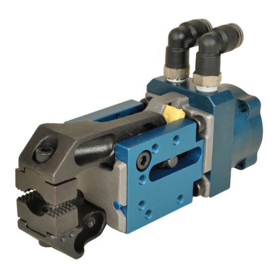
- Page 1 PGS10 Series Grippers User instructions for PGS10 Series Grippers Engineering GREAT Solutions...
- Page 2 User Instruction for PGS10 Series Gripper Table of contents Section Page Reference ......................I .......3 Purpose ......................II .......3 Scope ......................III .......3 Safety .......................IV .......3 Applicable Documents ..................V .......3 Equipment Required ..................VI .......3 Procedures ...................... VII .......3 Cleaning and Maintenance ................VIII .....10 Quality Assurance Requirements ..............IX .....10...
-
Page 3: Applicable Documents
User Instruction for PGS10 Series Gripper I. Reference: 001POL Quality Policy II. Purpose: This document instructs the operator how to use the PGS10 & 11 Grippers III. Scope: This work instruction covers Port Size and Operation, Unlocking of Jaws & Setting Open Jaw Angle. - Page 4 User Instruction for PGS10 Series Gripper B. Gripper Unlock 1. Release jaw by using a hex key or flat screwdriver and pushing on drive pin through slot in side plate C. Jaw Removal 1. Unlock gripper as shown in step B and remove pad(s) from existing jaws. Set a side for reassembly.
- Page 5 User Instruction for PGS10 Series Gripper C. Jaw Removal (cont.) 5. Remove bushing from lower jaw using a small flat screwdriver or hex key and set aside for re-assembly. Lower jaw should be rotated completely down before removal. Lift up on front of jaw by pad so there is an angle between jaw and frame.
- Page 6 User Instruction for PGS10 Series Gripper Setting Jaw Open Angle 1. Look for bumper which should be on the upper jaw side. Remove M5X12mm SHCS from side plate. If indirect sensor is in place of side plate remove M5X30mm from indirect sensor.
- Page 7 User Instruction for PGS10 Series Gripper F. Installing a Side Plate or Indirect Sensor (cont.) 2. If an Indirect Sensor is to be installed, move brass bushing in sensor to align with drive pin in gripper. This must be done to correctly install sensor. Align dowel pins with slots of frame.
- Page 8 User Instruction for PGS10 Series Gripper 3. Apply Loctite 262 to M5 X 8mm SHCS and insert into one of the jaws. Take replacement pads and insert it into the opposite side of the jaw with SHCS sticking out. Thread SHCS into pad and tighten to 72in-lb. Repeat step for other jaw. Chisel jaws only require one pad H.
- Page 9 User Instruction for PGS10 Series Gripper H. Calibrating In-Direct Sensor (cont.) b) Verify calibration: (1) Close the gripper with no material between the pads. The LED(s) should be off. (2) Close the gripper on a single blank of material. The Red LED(s) corresponding to you material range should be on.
- Page 10 User Instruction for PGS10 Series Gripper 3. Apply Red Loctite 262 or equivalent to sensor stud, place thru jaw and tighten sensor nut to 72in-lb. Cable should follow Cable storage loop the contour of the can be adjusted with gripper jaw...
- Page 11 User Instruction for PGS10 Series Gripper Chisel jaw / shovel Regular / flange jaw Single blank Movable jaw Opposing fixed Moveable jaw Opposing jaw thickness pad color jaw color pad color pad color Black (note 1) Black Black 0.50mm to 2.0mm...
Need help?
Do you have a question about the PGS10 and is the answer not in the manual?
Questions and answers