Table of Contents
Advertisement
Advertisement
Table of Contents

Summary of Contents for Kett FD-720
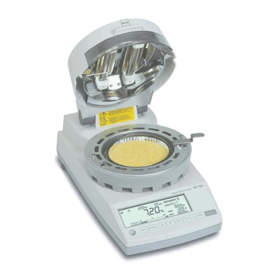
- Page 1 Infrared Moisture Determination Balance FD-720 Operating Manual...
- Page 3 Do not attempt to disassemble, modify or rebuild the infrared moisture tester. Doing so may result in accident, electric shock, etc. If you believe the unit may be malfunctioning, take it to an authorized Kett service center for service. Do not allow the unit to come in contact with water.
-
Page 4: Table Of Contents
Contents 1. Precautions to be observed when taking measurements ....6 2. Description of Features and Principles of Operation ......... 8 2-1 Principles of Operation ..................... 8 2-2 Features ........................8 2-3 Applications (i.e., materials which can be measured) ..........8 3. - Page 5 14-1 RS-232C Interface Specifications ................60 14-2 Setting Up and Transmitting Data ................61 14-2-1 Connecting the RS-232C cable ..............61 14-2-2 FD-720 settings .................... 61 14-2-3 Starting up the computer ................61 14-3 Computer Output Format ..................62 15. Maintenance ....................64 15-1 Performing Maintenance ..................
-
Page 6: Precautions To Be Observed When Taking Measurements
1. Precautions to be observed when taking measurements Be sure to follow proper procedures during operation When opening or closing the lid to the heater, always be sure to use the handle. Handle Be sure to put the wind shield, sample dish tray, handler, and sample dishes properly into place. - Page 7 Never place any easily flammable objects near the product The components of the infrared moisture tester can become very hot when measurements are being taken or immediately after measurements have been taken. The heat could cause objects or materials to catch fire if they were to come into contact with the unit, an d no easily flammable objects or materials should be kept near the product.
-
Page 8: Description Of Features And Principles Of Operation
Data memory The FD-720 is able to store up to 100 sets of measurement data in memory, thus making it possible to output large batches of data all at one time. Printer port... -
Page 9: Specifications
: Samples with a weight of 5 g or higher: 0.05% Samples with a weight of 10 g or higher: 0.02% When using standard samples and measuring conditions as determined by Kett Electric Laboratory. Measurement modes : Automatic halting mode... -
Page 10: Names Of Individual Parts And Components
4. Names of Individual Parts and Components 4-1 Names of Parts of Main Unit Heater lid Handle Observation window Heater Temperature sensor Wind shield Sample dish Sample dish handler Display Level Control panel Power switch Power conversion switch Power inlet RS-232C port Fuse holder Height adjustment legs... -
Page 11: Parts And Accessories
4-2 Parts and Accessories Sample dishes (2) Sample dish handler (2) Wind shield Sample dish tray Spoon & spatula set Spare (T8A 250V) fuses (2) Packages of aluminum foil sheets (Power cord) (Three-prong plug adapter) (10 per package) (2) Note: The shape of the power plug varies in different countries. The actual accessory may be different from the one in this illustration. -
Page 12: Display And Control Panel
5. Display and Control Panel 5-1 Display 1 2 3 $ Display as it appears with the power on. (All display items shown.) & Item Name Description Stability indicator This indicator lights up when the internal scale is stable. Measuring complete indicator This indicator lights up when measuring has been completed. -
Page 13: Control Panel Operations
5-2 Control Panel Operations The control panel keys are used to perform the following operations. Name Operation Used to start measuring or to abort a measuring operation. Also used to turn off the alarm which sounds to indicate that a measuring operation has been completed. -
Page 14: Assembly And Installation Of Main Unit
6. Assembly and Installation of Main Unit 1 Opening the package Open the package and check to make sure all listed items are included. 2 Installing the main unit • Place the main unit on a flat, stable surface where it will not be subject to vibrations or exposed to drafts or breezes. - Page 15 5 Ensuring that the unit is level Turn the two height adjustment legs located at both sides of the lower rear of the unit to adjust until the level bubble falls within the red circle. * The level is located to the left of the control panel. The tester is perfectly level if the bubble appears in the center of the red circle when viewed from directly above.
- Page 16 9 Placing the sample dish into the tester Please the sample dish gently down onto the sample dish tray. 0 Close the heater lid ! Connecting the power cord Insert the female end of the power cord into the power inlet located at the rear of he unit. Then insert the power plug into the power outlet.
-
Page 17: Tips On How To Ensure Accurate Measurements
7. Tips on how to ensure accurate measurements Points to remember when conducting multiple measurements in succession Placing a sample onto a sample dish which is already warm may cause moisture from the sample to evaporate before measuring is begun and cause errors to occur in measurement. Always be sure to use a cool sample dish when performing a second or subsequent measurements. - Page 18 Crushing samples consisting of large particles before measuring If samples consisting of large particles are measured in their original condition it not only takes longer for drying to completed to the center, but also may result in problems such as the surface of the sample becoming burned, thus making it impossible to obtain accurate measurements.
-
Page 19: How To Conduct Measurements
8. How to Conduct Measurements Before beginning a measurement, check to make sure that there is nothing remaining in the sample dish. Also be sure that all parts of the main unit are firmly fixed in place and be sure that the heater lid has been closed firmly before starting to perform measurements. - Page 20 Operating instructions Display 4 Performing a tare Shut the heater lid, check to make sure that the steady-state mark ( ) is displayed, and press the key. A series of hyphens and the word ‘TARE’ will be displayed, the sample dish will move vertically and a tare will be performed.
- Page 21 Operating instructions Display Never open the lid to the heater while a measurement is in progress. Doing so is not only hazardous but also could contribute to making it impossible to obtain accurate measurements. If it is absolutely necessary to open the lid to the heater while a measurement is in progress to view the sample material (or for some other reason) limit the time the lid is opened to 15 seconds or less.
- Page 22 Operating instructions Display ! Prepairing to perform the next measurement Leave the lid to the heater open to allow the tester to cool. When performing sequential measurements, leave an interval of about 1-2 minutes between each measurement and make sure that the tester has cooled before proceeding to the next measurement.
-
Page 23: Specifying Measuring Conditions
9. Specifying Measuring Conditions When using this tester to measure moisture or solid content, it is necessary to first specify the conditions (e.g., drying temperature or measuring mode) to be used in performing the measurement. The settings which may be specified are as described below. When necessary, it is also possible to save sets of measuring conditions (i.e., drying temperature, measur- ing mode, and bias). -
Page 24: Selecting The Conditions (Measuring Conditions Storage Area)
9-2-1 Selecting the CONDITIONS (Measuring conditions storage area) Below is described the procedure used to select the area in which measuring conditions are to be saved. This operation causes the measuring mode, drying temperature, bias, and other currently specified measuring conditions to be saved to the selected area. * At the time of shipment, the following settings are stored in measuring conditions storage areas 0~9: Measurement standard : Wet Base... -
Page 25: Selecting The Mode (Measuring Mode)
9-2-2 Selecting the MODE (Measuring mode) The ‘MODE’ (measuring mode) setting is used to specify the conditions under which measuring is to be completed. As shown in the table in subsection “9-1 Types of Settings”, the mode may be set to one of seven methods. - Page 26 2) Specifying settings for TIME (Timed halting) mode In timed halting mode, the measuring time is specified before the test and the sample is dried to determine its moisture (or solid) content. When the specified measuring time is reached, the test is halted. Measuring time may be specified in 1-minute increments anywhere in a range from 1 to 240 minutes or measuring may be specified to be performed over a continuous period of 12 hours.
- Page 27 3) Specifying settings for RAPID (High-speed drying) mode During the initial phase of measurement, the material is dried at a temperature higher than the specified drying temperature to speed up drying and reduce the amount of time required for performing measurements.
- Page 28 Step Key(s) used Operating instructions Display When the desired the rapid drying temperature maintenance conditions begins to flash, press the key. The high-speed settings will then be set and the highlight will shift to the selection of the halting conditions. The units area for timed halting mode (‘min’) or automatic halting mode (‘%’) will begin to flash.
- Page 29 4) Specifying settings for SLOW (Low-speed drying) mode In low-speed drying mode, the temperature is raised more gradually than when performing measurements under normal conditions, with it taking about 5 minutes from the time when measuring begins until the temperature reaches the specified drying temperature. Either ‘AUTO’...
- Page 30 5) Specifying settings for STEP (Stepped drying) mode In stepped drying mode it is possible to specify separate measuring conditions for up to a maximum of 5 steps. Specifying a separate drying temperature and separate measuring time for each step makes it possible to specify finer-grained sets of measuring conditions.
- Page 31 Step Key(s) used Operating instructions Display Pressing the key will cause the units to switch between minutes (‘min’) and a percentage (‘%’). Press the key until the desired units are displayed. When the desired units for the halting conditions (i.e., minutes or a percentage) begin to flash, press the key.
- Page 32 6) Specifying settings for COMPARE (Comparative measuring) mode Comparative measuring mode is used to calculate the bias (i.e., the difference between the predicted measurement and the measurement which would be obtained when operating in automatic halting mode) needed when conducting predictive measurements. When conducting predictive measurements, this mode should be used first to calculate the bias.
- Page 33 7) Specifying settings for PREDICT (Predictive measuring) mode This mode is designed for use in reducing the amount of time required for performing measurements by calculating a predicted final measurement from data obtained on changes in moisture content while drying is still in progress.
-
Page 34: Temp (Drying Temperature)
9-2-3 TEMP (Drying temperature) The following describes the procedure to be followed to specify the drying temperature to be used in drying samples when conducting measurements. While the drying temperature is set to 120°C as the default temperature at the time of shipment, depending on the type of sample, its moisture content, or other conditions, the proper drying temperature to use may vary. -
Page 35: Bias
• In most cases it is possible to change the measuring conditions used to make the measurements obtained using the FD-720 to match the expected (standard) values, but when such conditions would cause the sample to be burned, would cause the time required for measurement to become too long, or otherwise result in problems, a bias should be specified instead. -
Page 36: Menu Settings
10. Menu Settings Measurement standards, output data formats, and other parameters may be selected as needed. Always be sure to specify the desired settings before performing measurements. When changing settings, the same procedure is followed as when specifying settings for the first time. -
Page 37: Selecting Units (Measurement Standard And Minimum Display Units)
10-2-1 Selecting units (measurement standard and minimum display units) 1) Selecting the measurement standard This is used to select and specify the measurement standards to be used when performing mea- surements. There are three different types of measurement standards: measuring by changes in wet content, measuring by changes in dry content, and measuring by changes in solid content. -
Page 38: Specifying The Type And Format Of Output
10-2-2 Specifying the type and format of output The FD-720 may be connected to a separately sold printer or computer so that measurement data can be output to the printer or computer. 1 There are three types of output formats or output destinations as shown in the table below. - Page 39 How to specify the output format to be used Step Key(s) used Operating instructions Display With the display displaying the weight in grams, press the key. Press the key until the ‘OUTPUT’ menu item is displayed. Press the key. This will cause the highlight to be shifted to the output settings and cause the currently selected output destination to begin to flash.
- Page 40 Specifying the range of measurement values to be used (when ‘GRP’ has been selected) Step Key(s) used Operating instructions Display The currently selected minimum for the range of measurement values will begin to flash. Press the key or key until the desired minimum is displayed.
-
Page 41: Specifying Sample Codes
10-2-3 Specifying sample codes This section describes how to specify sample codes to be used when outputting measurements to a printer or computer. Sample codes may be specified as 4-character codes. Any digit from 0~9, and letter from A~Z, or a hyphen (i.e., ‘—’) may be specified as the value of the first or second character of the code. -
Page 42: Setting The Date And Time
10-2-4 Setting the date and time This section describes how to set the date and time. Note that while the internal clock is already set at the time of shipment, the following procedure should be used whenever resetting the clock. Also note that the date and time of measurement are output whenever measurement data is output to a printer or computer. -
Page 43: Cal (Scale Calibration)
The scale is designed to allow it to be calibrated. Calibration is performed at two points: 0 and 100 grams. The FD-720 may also be connected to a printer to make it possible to automatically generate calibration records in compliance with GLP, GMP, and ISO standards. (For further information, see “... - Page 44 Step Key(s) used Operating instructions Display With the value ‘0.000’ flashing, open the heater lid and remove the weight. Closing the heater lid and pressing the key causes a string of hyphens (i.e., ‘- - - -’) to be displayed, 0-point calibration to come to an end, and then an ‘END’...
-
Page 45: Specifying A Device Id
10-2-6 Specifying a device ID This section describes how to specify the device ID output when outputting data to a printer or computer. The device ID is an 8-character ID which may be set using the following characters: digits from 0~9, letters from A~Z, and hyphens (i.e., ‘—’). How to specify a device ID Step Key(s) used... -
Page 46: Specifying A Password
10-2-7 Specifying a password In order to prevent the specified measuring conditions from being modified unexpectedly, a pass- word may be specified to prevent other users from changing the specified conditions. The pass- word is 4 characters in length and may be set using the following characters: digits from 0~9, letters from A~Z, and hyphens (i.e., ‘—’). -
Page 47: Specifying The Power Settings
Note that this setting must be specified when using the FD-720 in countries outside of Japan or whenever there is a change in the type of power source being used. -
Page 48: Error Messages
If the error cannot be removed by following the procedures described below, then you should contact the vendor from which you purchased the unit or the Kett Tokyo sales office or a local Kett office or sales office for assistance. - Page 49 If any of the following errors are displayed, it indicates that a failure or breakdown of internal parts or components has occurred. Contact the vendor from which you purchased the unit or the Kett Tokyo sales office or a local Kett office or sales office for assistance.
-
Page 50: Predictive Measurements
The FD-720 has been designed to treat the final predicted value as having been obtained when the range of variation falls within the predicted value convergence range. - Page 51 Bias is used to change the average lower limit of fixed values with respect to predicted measure- ment values. On the FD-720, a bias of anywhere from –9.99 to +9.99 percent may be specified. When performing a comparative measurement, the FD-720 automatically requests a bias to be used to correct measurements to match those obtained in automatic halting mode.
-
Page 52: Procedure For Obtaining Predicted Measurements
12-2 Procedure for Obtaining Predicted Measurements 1) Use the comparative measuring mode to calculate the bias to be specified to obtain the pre- dicted measurement. (See “12-2-1 Calculating the bias to be specified when operating in predictive measurement mode” on p. 52 for instructions on how to do so.) 2) Use the bias calculated in comparative measuring mode in step 1) to specify the bias, perform the measurement, and evaluate the predicted measurement. - Page 53 Step Operating instructions Display Completion of measurement Measuring will be completed when the conditions specified for automatic halting mode have been met. When measuring is completed, the bias will be displayed in the bias display area. If no predicted measurement is displayed even after 30 minutes has elapsed from the time when measuring was initiated, it is probable that it is impossible to obtain a predicted measurement.
-
Page 54: Evaluating Predicted Measurements
12-2-2 Evaluating predicted measurements Step Operating instructions Display With the mode set to comparative measuring mode, specify the bias calculated following the procedure described in 12-2-1 In the example shown here, a bias of 0.60 percent has been specified. (For information on the bias, see “9-2-4 Bias”... -
Page 55: Obtaining Predicted Measurements
12-2-3 Obtaining predicted measurements Step Operating instructions Display Set the mode to predictive measuring mode. (9-2-2 “7) Specifying settings for PREDICT (Predictive measuring) mode” on p. 33 for instructions.) Specify the same settings for the predicted value convergence range and drying temperature as those used in comparative measuring mode (subsections 12-2-1 and 12-2-2). -
Page 56: Printing Output To A Printer (Option)
13. Printing Output to a Printer (Option) The FD-720 may be connected to a printer to make it possible to output measurement data or other information to the printer. Output which may be generated includes data consisting of inter- mediate or final measurements, sample codes, and measurement times. - Page 57 * Note on the decimal precision of printed weight data Although the minimum weight which may be displayed by the FD-720 is 0.001 grams, weights (Mass) are printed to a precision of 4 decimal points because the values printed consist of averages from 7...
- Page 58 [Graph output (GRP)] Supplier : KETT ELECTRIC LABORATORY Model : FD-720 Serial number : AC00001 Device ID : ABCD-123 Sample code : B-20 Date & time of measurement : 2003/08/08, 15:07 Measuring conditions storage area : 0 Measurement standard : Dry base Measurement mode : Comparative measuring mode Drying temperature : 110°C...
-
Page 59: Outputting Past Measurement Data
Printing calibration records when performing a calibration Supplier : KETT ELECTRIC LABORATORY Model : FD-720 Serial number : AC00001 Device ID : ABCD-123 Time of measurement : 2003/08/08 15:18 Signature 13-2 Outputting Past Measurement Data Record are stored of up to 100 past measurements in sequence from the most recent to the oldest. -
Page 60: Computer Interface
14. Computer Interface The RS-232C interface may be used to connect the FD-720 to a computer with an RS-232C interface and output measurement data to that computer. 14-1 RS-232C Interface Specifications Interface type : RS-232C Communications method : Asynchronous communication... -
Page 61: Setting Up And Transmitting Data
RS-232C cable into the RS-232C port of the computer. If the FD-720 has been moved, check to make sure that the FD-720 is level and, if not readjust until it is level. (See “6. Assembly and Installation of Main Unit” on p. 14 for instructions.) 14-2-2 FD-720 settings Turn on the power to the FD-720 and set the measurement data output destination to ‘PC’. -
Page 62: Computer Output Format
14-3 Computer Output Format Interface type : RS232C Numeric output format : JIS (ASCII) Delimiter code : 0x09 (tab) Delimiter : 0x0D (CR) + 0x0A(LF) Title output format at time of start of measurement (Underscore characters (i.e., ‘_’) are used below to indicate blanks (i.e., ‘20’ in hexadecimal) “KETT_ELECTRIC_LABORATORY”... - Page 63 Stepped mode format “_Mode_:_Step” + delimiter tab + “Temp (C)” + tab + “Time (min.)” + delimiter The following output then appears the same number of times as the number of specified steps: “_Step” + “X” (1-byte step number) + tab + “XXX” (3-byte temperature setting) + tab + “XXX”...
-
Page 64: Maintenance
15. Maintenance 15-1 Performing Maintenance Always be sure to remove the plug from its socket before performing maintenance. Warning 1 Removing parts and components Remove the sample dish first, followed by the sample dish handler, sample dish tray, and wind shield in order. -
Page 65: Replacing Fuses
15-2 Replacing Fuses 1 Remove the power cord from the unit. 2 The fuse holder is located at the rear of the unit. Insert a slot screwdriver or similar tool from the top of the fuse holder, and pull the fuse holder towards your body. - Page 68 0706•PA•0201•200...
Need help?
Do you have a question about the FD-720 and is the answer not in the manual?
Questions and answers