
Summary of Contents for Intelligen INS-500
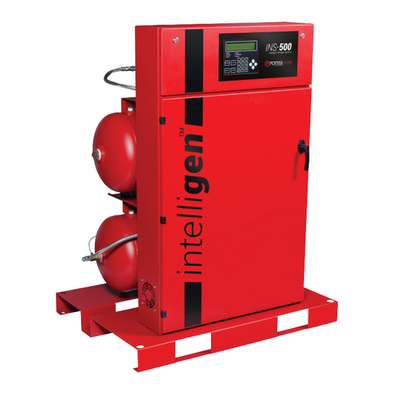
- Page 1 INS-500/1000 Nitrogen Generators Installation, Operation, and Instruction Manual St. Louis, MO Manual #5403645 - A 800-325-3936 6/17 www.pottersignal.com...
-
Page 2: Warranty Information
INS-500 & INS-1000 • 5403645 • REV A • 6/17 WARRANTY INFORMATION GENERAL PROVISIONS & LIMITATIONS Potter Electric Signal Company, LLC (the “Company”) warrants to each original purchaser (“Purchaser”) of its new products from the Company or its Authorized Distributor that such products are, at the time of delivery to the Purchaser, made with good materials and workmanship. -
Page 3: Table Of Contents
INS-500 & INS-1000 • 5403645 • REV A • 6/17 ontents Safety Guidelines ..................................4 Important Notice to Users ..............................4 Unpacking ................................... 4 General Safety Information ..............................4 System Overview ..................................6 Key Terms ................................... 6 ™ IntelliGen Controller ................................6 INS-500/1000 Exterior View ...............................7 INS-500/1000 Interior View ................................ -
Page 4: Safety Guidelines
INS-500 & INS-1000 • 5403645 • REV A • 6/17 Safety Guidelines This manual contains safety information that is important to know and understand. This information is provided for the safety of installers, operators, and users of the Potter Nitrogen Generator as well as equipment. To help recognize this information, observe the following symbols. - Page 5 INS-500 & INS-1000 • 5403645 • REV A • 6/17 The warnings in this manual cover most known potential hazards, but by definition cannot be all-inclusive. If the user employs an operating procedure, item of equipment, or a method of working that is not specifically recommended by Potter Electric Signal Company, the user must ensure that the equipment will not be damaged or become hazardous to persons or property.
-
Page 6: System Overview
The INS-500 and the INS-1000 are FM approved per FM 1035 "Nitrogen Generators". • The INS-500 has a Bypass Fill Capacity of 500 gallons at 40 PSI and a Total System Capacity of 1,850 gallons • The INS-1000 has a Bypass Fill Capacity of 1,000 gallons at 40 PSI and a Total System Capacity of 3,400 gallons... -
Page 7: Ins-500/1000 Exterior View
INS-500 & INS-1000 • 5403645 • REV A • 6/17 INS-500/1000 Exterior View Fig. 1 1. Upper Cabinet Latches (Qty. 2) 8. N Tank Inlet Valve (V02) 2. IntelliGen Display 9. Air Tank ™ 3. Air Compressor Power Switch 10. Air Tank Gauge 4. -
Page 8: Ins-500/1000 Interior View
INS-500 & INS-1000 • 5403645 • REV A • 6/17 INS-500/1000 Interior View Fig. 2 1. Nitrogen Membrane (M01) 12. N Bleed Valve (V04) 2. Flow Control Valve (FCV01) 13. Bypass Solenoid Valve (XV03) 3. Back Pressure Regulator (PRV02) 14. Coalescing Filter 5µm (F01) 4. -
Page 9: Intelligen ™ Display
SILENCE – The "SILENCE" button will silence the Trouble Horn on the IntelliGen Nitrogen Generator. ™ CLEAR – The "CLEAR" button will clear all Troubles. MAINT – The "MAINT" button will display the Maintenance Menu. PURGE – The "PURGE" button will bring up the Purge Menu on the IntelliGen Display. ™... -
Page 10: Installation Of The Nitrogen Generator
INS-500 & INS-1000 • 5403645 • REV A • 6/17 Installation of the Nitrogen Generator On arrival, do a full inspection by checking all packages and crates in the shipment for damage. If damage is found, sign for the damage or refuse the shipment. Contact the carrier immediately and file a shipping damage claim with the carrier. - Page 11 INS-500 & INS-1000 • 5403645 • REV A • 6/17 Pipe the provided 10' of the 3/8” drain tubing to the floor drain in the sprinkler room. Do not pipe the drain tubing upward. Ensure drain tubing is restrained. See Fig. 6.
-
Page 12: Wiring Of The Nitrogen Generator
Run a dedicated electrical circuit with an electrical disconnect switch to sprinkler room. To wire the INS-500 or INS-1000, open the front panel at the top of the nitrogen cabinet to access wiring terminal blocks. Use the 1/2" or 3/4" knockouts on back of cabinet for electrical conduit. See Fig. 9. - Page 13 INS-500 & INS-1000 • 5403645 • REV A • 6/17 Using the other 1/2" knockout on the back of the cabinet, wire the IntelliPurge Nitrogen Purge Valve to the IntelliGen ® ™ Controller using 3 wire cable (22 AWG recommended). See the IntelliPurge Section on page 21 for more details.
-
Page 14: Nitrogen Generator Operation
INS-500 & INS-1000 • 5403645 • REV A • 6/17 Nitrogen Generator Operation Initial Set Up: Before beginning, make sure the water supply to the sprinkler system is turned off. Make sure all piping connections have been made in accordance with the installation instructions. - Page 15 13. If the nitrogen generator is isolated from the sprinkler system: • The air compressor of the INS-500 should take no longer than 8 minutes to pressurize both tanks and turn off. • The air compressor of the INS-1000 should take no longer than 6 minutes to pressurize both tanks and turn off.
-
Page 16: Nitrogen Functionality Test
If the nitrogen generator is isolated from the sprinkler system: The INS-500 should take no longer than 8 minutes to pressurize the nitrogen tank to 80 PSI. The INS-1000 should take no longer than 4 minutes to pressurize the nitrogen tank to 80 PSI. -
Page 17: Filling The Sprinkler System And Purging
The pressure in the nitrogen tank and the air tank will decrease rapidly, causing the nitrogen generator to switch to Bypass Mode. The amber LED labeled "BYPASS" will turn on and the "Mode" on the IntelliGen Display will turn to "Bypass Mode". This ™... -
Page 18: Purging With Intellipurge ® Nitrogen Purge Valve (Ins-Pv)
Nitrogen Purge Valve (INS-PV) is connected to a nitrogen generator or an INS-PV, the S1 toggle switch ® will be DISABLED. 14. Return to the nitrogen generator. 15. If an INS-PV is connect to the nitrogen generator, press the “PURGE” button on the IntelliGen Display keypad. ™ 16. Follow all prompts. -
Page 19: Purging With Potter Nitrogen Purge Valve (Ngp-Spv)
INS-500 & INS-1000 • 5403645 • REV A • 6/17 Purging with Potter Nitrogen Purge Valve (NGP-SPV): Fig. 19 See Bulletin #5401520 for full details on installing and purging of the NGP-SPV. Go to the end of the sprinkler system(s) where the NGP-SPV(s) is installed. Each riser should have one NGP-SPV purge valve. -
Page 20: Intelliview ™ Dashboard Connectivity
You will receive an e-mail confirmation with an account verification link. Once logged in, click the "Register Generator" button on the Dashboard Overview page. Enter the unit’s MAC ID Number and the Serial Number which can be found on the IntelliGen Controller inside the cabinet. -
Page 21: Intellipurge ® Wiring And Networking
® Combining the two products creates a quick seamless experience when it comes to protecting and monitoring your sprinkler system. Use stranded 3 wire (22 AWG gauge) to run from the IntelliGen Controller to the first INS-PV. ™ Maximum wire length for network is 6500 ft. Maximum number of INS-PV devices on network is 27. Maximum number of INS- RA devices on network is 4. -
Page 22: Maintenance And Part Replacements
If maintenance on the nitrogen generator is not done within 250 compressor operating hours, the nitrogen generator will show a trouble condition. To reset the maintenance timer and get the maintenance alert to reset, go to the IntelliGen Display. -
Page 23: Standard Maintenance (Every 1,000 Compressor Operating Hours)
INS-500 & INS-1000 • 5403645 • REV A • 6/17 Standard Maintenance (Every 1,000 Compressor Operating Hours) Tools Needed: • 13/16” wrench • • 5/32" hex key • Potter Filter Elements Kit (#0090206) • Channel Lock • Potter Air Intake Elements Kit (#1119622) Drain all pressure from the nitrogen generator before proceeding and turn off power to unit at the contractor installed electrical disconnect. -
Page 24: Compressor Air Intake Filters
When the pressure has been drained from the nitrogen generator clean or replace the air intake filter elements. Go to the air compressor located on the top of the nitrogen tank. Locate the black filter enclosures. There will be two (2) on the INS-500 and four (4) on the INS-1000. See Fig. 26. Fig. 26 Using a 5/32"... -
Page 25: Filter Elements
INS-500 & INS-1000 • 5403645 • REV A • 6/17 12. Remove the screen and clean all debris. Wipe the inside of the strainer with a rag. 13. Reinstall the screen into the strainer. 14. Retighten the strainer screen cap. - Page 26 INS-500 & INS-1000 • 5403645 • REV A • 6/17 17. Using a 13/16” wrench loosen the filter bowl from the filter body. See Fig. 32. Fig. 32 CAREFULLY WRENCH HERE DO NOT PLACE ONLY WRENCH HERE Fig. 33 It is extremely important that you only unscrew the drain bowl from the filter body. The float adjustments at the bottom must remain in auto.
-
Page 27: Resetting Maintenance Alert And Checking For Leaks
33. If the nitrogen generator is isolated from the sprinkler system: The air compressor of the INS-500 should take no longer than 8 minutes to pressurize the two tanks and turn off. The air compressor of the INS-1000 should take no longer than 6 minutes to pressurize the two tanks and turn off. -
Page 28: Air Compressor Replacement
INS-500 & INS-1000 • 5403645 • REV A • 6/17 Air Compressor Replacement Isolate the nitrogen generator from the sprinkler system and relieve pressure. Disconnect the power to the nitrogen generator using lockout-tagout procedure. Disconnect wires in junction box on the air compressor. -
Page 29: Maintenance Alerts And Actions
INS-500 & INS-1000 • 5403645 • REV A • 6/17 Maintenance Alerts and Actions A maintenance alert is noncritical to the operation of the nitrogen generator. The maintenance light will turn on and a maintenance alert will appear on the IntelliGen Display and IntelliView website, and an e-mail will also be sent. -
Page 30: Trouble Alerts And Probable Causes
INS-500 & INS-1000 • 5403645 • REV A • 6/17 Trouble Alerts and Probable Causes A trouble alert is a critical alert to the operation of the nitrogen generator. The trouble light will turn on and a trouble alert will... - Page 31 INS-500 & INS-1000 • 5403645 • REV A • 6/17 Trouble Alert #5 - Excessive Membrane Cycling Issue: Nitrogen valves turn ON 16 (INS-500) or 24 (INS-1000) times in 4 hours. Probable Cause: Leak on sprinkler system. Leak on nitrogen tank.
-
Page 32: Troubleshooting
If the nitrogen generator is isolated from the sprinkler system: The INS-500 should take no longer than 8 minutes to pressurize the nitrogen tank to 80 PSI. The INS-1000 should take no longer than 4 minutes to pressurize the nitrogen tank to 80 PSI. -
Page 33: Normal Operating Parameters Of The Ins-500 And The Ins-1000
INS-500 & INS-1000 • 5403645 • REV A • 6/17 Normal Operating Parameters of the INS-500 and the INS-1000 The Potter IntelliGen Nitrogen Generators use a two tank system design to deliver high purity nitrogen to the fire protection ™... -
Page 34: Nitrogen Generator Leak Detection System
INS-500 & INS-1000 • 5403645 • REV A • 6/17 Nitrogen Generator Leak Detection System Each Potter IntelliGen Nitrogen Generator comes with an integrated Leak Detection System. The Leak Detection System uses ™ pressure decays to calculate the actual pressure loss in 24 hours, or the Leak Rate of the sprinkler system. -
Page 35: To Change The Leak Rate Warning Set Point
11. Press "ESC" to return to main menu. The Leak Rate is also calculated based on the size of the sprinkler system the nitrogen generator is protecting. The INS-500 is factory set at 1,850 gallons (max) and the INS-1000 is factory set at 3,400 gallons (max). This can be adjusted lower if the units are servicing smaller systems. -
Page 36: Ins-500/1000 Dimensional Drawings
INS-500 & INS-1000 • 5403645 • REV A • 6/17 INS-500/1000 Dimensional Drawings DRAIN CONNECTION... -
Page 37: Ins-500/1000 Piping Instrumentation Diagram
INS-500 & INS-1000 • 5403645 • REV A • 6/17... -
Page 38: Wiring Diagrams
INS-500 & INS-1000 • 5403645 • REV A • 6/17 13NO 14NO... -
Page 39: Ins-500/1000 Single Phase 208-240Vac
INS-500 & INS-1000 • 5403645 • REV A • 6/17 13NO 14NO... -
Page 40: Ins-500/1000 Three Phase 208-240Vac
INS-500 & INS-1000 • 5403645 • REV A • 6/17 13NO 14NO... -
Page 41: Ins-500/1000 Three Phase 460-480Vac
INS-500 & INS-1000 • 5403645 • REV A • 6/17 13NO 14NO... -
Page 42: Menu Trees
INS-500 & INS-1000 • 5403645 • REV A • 6/17 Menu Trees 1. Menu Tree 1 Title Screen Model Number Status: Mode: N2 Tank: Leak Rate (LR): 5) Settings 1) System Status 2) View History 3) Maintenance 4) Purge Menu Tree 2... -
Page 43: Menu Tree 2
INS-500 & INS-1000 • 5403645 • REV A • 6/17 2. Menu Tree 2 Main Menu 1) System Status Screen 2) Purge Status 1) Generator Status Device Number: N2 Level: Days Remaining: Compressor: Total Run Time: Average Cycle Time Purge Mode: Purge Status... -
Page 44: Menu Tree 3
INS-500 & INS-1000 • 5403645 • REV A • 6/17 3. Menu Tree 3 Main Menu 2) View History History 1) Generator History 2) INS-PV History Generator INS-PV History: History: Scrollable list of Scrollable list of connected all history from... -
Page 45: Menu Tree 4
INS-500 & INS-1000 • 5403645 • REV A • 6/17 4. Menu Tree 4 Main Menu 3) Maintenance 1) Standard 2) Excessive Nitrogen Nitrogen Demand Maintenance Maintenance Timer: Excessive Nitrogen Demand: Reset Maintenance Timer Clear Maintenance Alert [ENTER] [ENTER] Reset Maintenance Timer... -
Page 46: Menu Tree 5
INS-500 & INS-1000 • 5403645 • REV A • 6/17 5. Menu Tree 5 Main Menu 4) Purge 1) Start Purge 3) Settings 2) Cancel Purge Purge Start Cancel Purge Settings 1) All Devices 1) All Units 1) Purge Settings... -
Page 47: Menu Tree 6
INS-500 & INS-1000 • 5403645 • REV A • 6/17 6. Menu Tree 6 1) Purge Settings Purge Settings Restore Factory Default 1) Set All Units 2) Set Individual INS-PV 1) All Units 3) Purge Scheduling 2) Individual INS-PV 4) Restore Factory Default... -
Page 48: Menu Tree 7
INS-500 & INS-1000 • 5403645 • REV A • 6/17 7. Menu Tree 7 5) Settings Main Menu 1) Network 2) Date/Time 3) Leak Rate 4) Blow Down 5) BMS Test 6) Admin. Leak Rate Screen Air Tank Blow Down...
Need help?
Do you have a question about the INS-500 and is the answer not in the manual?
Questions and answers