
Summary of Contents for Dipl.-Ing. H. Horstmann SMART NAVIGATOR
- Page 1 Dipl.-Ing. H. Horstmann GmbH Humboldtstraße 2 42579 Heiligenhaus www.horstmanngmbh.com Instructions for Use SMART NAVIGATOR 14 September 2010...
-
Page 2: Table Of Contents
3.3.2 Other events ..........................13 3.3.3 Analog data ..........................13 3.5 SMART NAVIGATOR @Smart receiver Registration Procedure ..........14 Part 4 - Technical Data .......................... 15 4.1. Product Foto & Label Information ....................16 ... - Page 3 Instructions for Use Dipl.-Ing. H. Horstmann GmbH General Information! Before installing and operating this instrument carefully read and understand the contents of this manual. Store this manual in a safe place for any possible questions in the future. Please, enter the type and ordering number of the device here: _______________________________.
-
Page 4: Compliance Statements
(2) this device must accept any interference received, including interference that may cause undesired operation Warning Changes or modifications to the SMART NAVIGATOR not expressly approved by Dipl.-Ing. H. Horstmann GmbH could void the user's authority to operate the equipment. -
Page 5: Part 1 - Introduction
1.3 I NTENDED USE The SMART NAVIGATOR is an overhead faulted circuit indicator that is designed and engineered for Smart Grid – Distribution Automation applications. The SMART NAVIGATOR is installed on overhead distribution circuits and transmits event based fault information in addition to continuous circuit status information. -
Page 6: Product Overview
The SMART NAVIGATOR is specially designed and engineered for Smart Grid – Distribution Automation (DA) applications. The SMART NAVIGATOR indicates a fault locally by LED and also over a wireless radio link. The wireless link is established with a SMART NAVIGATOR compatible concentrator that makes this information available for remote monitoring via a RTU. -
Page 7: Part 2 - Functionality
Instructions for Use Dipl.-Ing. H. Horstmann GmbH 2 - F UNCTIONALITY 2.1. D EVICE ESCRIPTION Battery Compartments Figure 2.1: NAVIGATOR 2D View SMART NAVIGATOR... -
Page 8: Fault Detection, Indication And Reset
AULT ETECTION The SMART NAVIGATOR constantly monitors the load current on the conductor and electronically adjusts the trip curve position accordingly. This self adjustment is defined as load tracking function. The initial or out of the box setting is the most left trip curve, the reference trip setting is displayed in the figure below. -
Page 9: Fault Indication And Line Monitoring By Radio Signal
2.3.1 P RIORITY VENTS COMMUNICATE BY EXCEPTION If a SMART NAVIGATOR detects a priority event such as a fault alarm it will initiate communication immediately. Therefore the SMART NAVIGATOR will initiate contact with the SMART CONTROLLER and transmit such events immediately. -
Page 10: Test/Reset Contacts
Dipl.-Ing. H. Horstmann GmbH Instructions for Use 2.4. TEST/RESET C ONTACTS The SMART NAVIGATOR features two reed contacts marked TEST and RESET that can be activated with a magnet. 2.4.1 T & R ESET AGNET The test & reset magnet is a permanent magnet retained by a specially designed housing allowing it to fit universal and shot gun type hot sticks. -
Page 11: Energy Supply
“armed & ready” to register switching into faults at any time. The SMART NAVIGATOR is designed for an operational time of 15 years. If it detects that its battery is approaching the end of its service life, the SMART NAVIGATOR will activate the low battery event. -
Page 12: Part 3 - Installation & Operation
Dipl.-Ing. H. Horstmann GmbH Instructions for Use 3 - I & O NSTALLATION PERATION 3.1. S AFETY NSTRUCTIONS Installation should be carried out observing appropriate safety regulations and the use of proper protective equipment such as hot sticks. Operators must maintain safe clearance from electrical power lines in accordance with applicable utility and government rules and regulations. -
Page 13: Smart Navigator - Operation
SMART NAVIGATOR sends out a Radio Test Signal “FCI On”. 5. Reset (FCI OFF): If the LED indication of the SMART NAVIGATOR stops either by current, time or manual (by magnet) the SMART NAVIGATOR sends out a Reset signal (FCI off). -
Page 14: Smart Navigator @Smart Receiver Registration Procedure
Hold the magnet close to the RESET point of the SMART NAVIGATOR until a yellow LED in the SMART NAVIGATOR lights up twice. If after a maximum of 10 seconds either a red LED or no LED has flashed at all, the registration procedure has failed (Please retry in such case). -
Page 15: Part 4 - Technical Data
Instructions for Use Dipl.-Ing. H. Horstmann GmbH 4 - T ECHNICAL TECHNICAL DATA Corresponding to ANSI / IEEE Std 495-2007 Electricial Data: Trip current (unleveled) 50 A - 1200 A / 200 ms Local indication / Flashing frequency Super bright red LED / 30 per minute... -
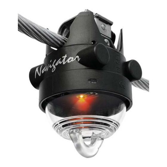
Page 16: Product Foto & Label Information
Dipl.-Ing. H. Horstmann GmbH Instructions for Use 4.1. P & L RODUCT ABEL NFORMATION Label with FCC ID IC ID SMART NAVIGATOR...
Need help?
Do you have a question about the SMART NAVIGATOR and is the answer not in the manual?
Questions and answers