Advertisement
Quick Links
Hardware and Installation Guide
Plan The Installation
Verify Power, Ground and Ignition. Be sure to check each source (power, ground and
ignition) to ensure that the proper signaling exists. This is typically accomplished with a
multi-meter.
Before drilling any holes or running any wires, decide where each hardware component
will be located (LMU, antennas, peripherals, etc.). Be sure that the cables to the LMU are
not bent or constricted in any way. Also make sure that the LMU is kept free from direct
exposure to the elements (sun, heat, rain, moisture etc...).
Be advised that an installation that violates the environmental specifications of the
LMU will void the warranty.
The best way to ensure a trouble-free installation is to consider your options and make
some decisions before you start. Take a look at the vehicle and determine how to best
install the LMU for the following purposes:
Accurate data gathering and simulation of how customers actually use your
•
solution
•
Ongoing monitoring and maintenance of LMU equipment
Accidental or intentional alteration of the equipment or cable connections
•
The following sections cover some of the issues to consider when planning your LMU
installation.
LMU-5000™
Advertisement

Summary of Contents for Actsoft LMU-5000
- Page 1 LMU-5000™ Hardware and Installation Guide Plan The Installation Verify Power, Ground and Ignition. Be sure to check each source (power, ground and ignition) to ensure that the proper signaling exists. This is typically accomplished with a multi-meter. Before drilling any holes or running any wires, decide where each hardware component will be located (LMU, antennas, peripherals, etc.).
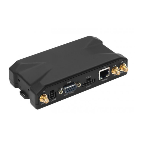
- Page 2 Size and Placement of LMU Unit The dimensions of the LMU should be taken into account, particularly when installing in a vehicle: Whether you intend to place the LMU under a seat or into a cavity behind the vehicle’s interior molded trim, be sure the LMU will fit before drilling any holes or running cable •...
- Page 3 Status LEDs The LMU-5000™ is equipped with two Status LEDs, one for GPS and one for COMM (wireless network status). The LEDs use the following blink patterns to indicate service: LED #1 (Comm LED - Orange) Definitions l i a...
- Page 4 Placement of Antennas Placement of Combination and Internal Antennas When dealing with combination antennas, it is more important to considered GPS performance over Comm performance. GPS signal strengths are much lower than those typically seen by cellular networks supported by the LMU. In order to maximize the performance the LMU should have a clear view of the sky as possible.
- Page 5 I/O Connector The LMU-5000™’s features expanded I/O capabilities via its 22-Pin Molex 43045-2202 connector. Its pin-out is as follows: Signal 5C889 Input or Description Name Color Output Input 1 Input 1 – Digital Input Blue Input Input 2 Input 2 – Digital Input...
-
Page 6: Digital Inputs
I/O Descriptions The LMU-5000™ provides the following inputs and outputs (I/O): Digital Inputs Input 0: Ignition Sense (Always biased low) Input 1: Generic Digital Input (Biased high or low/ S-158 Bit 1) Input 2: Generic Digital Input (Biased high or low/ S-158 Bit 2) - Page 7 Ignition and Inputs The LMU-5000™ provides up to 7 High/low selectable inputs and one Ignition Sense input.. These inputs are protected from typical vehicle transients and can be directly connected to most vehicle level logical inputs from 4 volts up to the vehicle power input level (typically 12 VDC).
- Page 8 Connect power, ignition, and ground. The power input (red wire) must be connected to a constant (un-switched) +12 VDC or +24 VDC supply; preferably, connected directly to the vehicle battery terminal or as close to it as possible. This connection point should be fuse protected to not more than 5 Amps.
Need help?
Do you have a question about the LMU-5000 and is the answer not in the manual?
Questions and answers