
Summary of Contents for UnderTone Audio MPEQ-1
-
Page 1: Table Of Contents
UT A UnderToneAudio MPEQ-1 User Manual Version 1.0 1. INTRODUCTION 2. POWERING UP 3. RACK MOUNTING 4. AUDIO CONNECTIONS 5. FRONT PANEL CONTROLS 6. THE EQUALIZER The Filters The 4 Parametric Bands Series Vs. Parallel Notch Mode Coming Soon: 7. PRESET SETTINGS... -
Page 2: Introduction
Class A equalizers ever built as well as a wonderfully flexible, beautiful sounding Class A Mic Preamp/DI. The MPEQ-1 packs a huge amount of Class A audio power into a single rack unit. Whether you are tracking or mixing, we are confident you will find the MPEQ-1 to be an indispensable tool in the music making process. - Page 3 After I had been using the EQ for months and months in the first UTA console, I started to real- ize that there were certain shapes involving combinations of bands, that were being difficult to create. This was a result of the unique type of “cutting” the EQ does combined with the parallel architecture of the EQ circuit.
-
Page 4: Powering Up
VU backlight LED is the indication that the MPEQ-1 is powered up and ready for use. The MPEQ-1 is protected by a “slow blow” or time delay fuse. The fuse can be found mounted in the removable tray (see Picture 3). -
Page 5: Rack Mounting
(horizontally) SUCKS for thermal dissipation. If you have the option of mounting the MPEQ-1 vertically it is unquestionably the best way to do it (It is also best for pretty much all rack mount gear). -
Page 6: Audio Connections
MIC IN (REAR) - This is one of 2 input connectors available for getting signal into the mic preamp. The rear mic input is convenient to use if the MPEQ-1 is rack mounted and wired to a patch bay. The rear mic input connector will automatically be disconnected as soon as an XLR or 1/4”... -
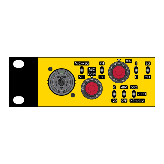
Page 7: Front Panel Controls
Plugging in a 1/4” instrument cable allows you to use the MPEQ-1 as a DI. When a 1/4” cable is plugged in, both the front and rear mic inputs are disabled. 2. MIC->EQ vs. SEP - When this toggle switch is in the up or “MIC->EQ” position, the signal from the mic pre will be sent directly to the input of the EQ. - Page 8 7. 50Ω/200Ω/Xfrmrless - This 3 position toggle switch selects the transformer mode for the input of mic pre- amp. 50Ω - In the “UP” or “50Ω” position, the input transformer is configured for a low impedance high gain input. This setting works especially well for passive ribbon microphones. You will typically get an added 3 or 4 dB of gain with no additional amplifier noise.
- Page 9 12. FREQUENCY/Q CONTROL (PARAMETRIC BAND) - This dual concentric potentiometer allows you to select the frequency being adjusted and the “Q” or “Bandwidth” of the adjustment being made. The Upper Knob controls the “Q” or “Bandwidth” . In the fully counter-clockwise position, you get the widest “Q”...
- Page 10 18. POWER SWITCH - This switch turns on or off the power for the MPEQ-1. In the up position, the power is turned on. In the down position, the MPEQ-1 will be powered off. The LED lighting in the...
-
Page 11: The Equalizer
EQ functions, see Section 4 (Front Panel Controls). There are far too many possible combinations of settings and curves that can be created by the MPEQ-1 to be able to show graphs of all of them. We will only be showing graphs of settings with a frequency selection of 1.5K and in either LP or High Shelf modes. - Page 12 Fig. 4 Selected frequency of roll o (1.5K) Roll O quickly transitions to a 12dB/Octave slope EXAMPLE OF ROLL OFF WITH LOW PASS FILTER SET AT 1.5K WITH “Q” AROUND THE 12 O’CLOCK POSITION Fig. 4 illustrates how increasing the “Q” setting doesn’t actually change the dB/octave value, but changes how quickly the roll off transitions into the 12dB/octave roll off.
- Page 13 I rolled off at the point of the lowest note being played. With the “Q” control on the MPEQ-1 High Pass Filter, I can roll off at the lowest frequency, then restore the natural body to the sound by adding a boost or resonance at the lowest frequency that the instrument is playing.
-
Page 14: The 4 Parametric Bands
THE 4 PARAMETRIC BANDS The 4 parametric bands have 2 configurations. The HF and HMF bands can blend between a peak shape and a “High Shelf” . The LMF and LF bands can blend between a peak shape and a “Low Shelf”... - Page 15 In Fig. 8, You can see what happens as you continue to turn the shape control past the 12 o’clock position. This is the range of the shape control where you can actually change the slop or con- tour of the shelf. This allows you to emulate the shelf EQ of pretty much any other shelf EQ ever made.
- Page 16 In Fig. 9 We will look at what happens when you start to combine the “Q” control with a shelf shape. Fig. 9 SHAPE SHAPE SHAPE SHAPE SHAPE SHAPE SHAPE The curves in this graph show what happens when you progressively increase the Q (starting fully counter-clockwise and turning the knob clockwise) of a conventional shelf shape.
- Page 17 In Fig.10 We will look at the range of widths available by adjusting the Q control with the shape control in the peak or fully counter-clockwise position. Fig. 10 SHAPE SHAPE SHAPE SHAPE SHAPE SHAPE SHAPE The curves in this graph shows what happens when you have the shape control in the peak (fully counter clockwise position) while turning the Q control clockwise starting from the fully counter-clockwise position.
-
Page 18: Series Vs. Parallel
The green curve was created by boosting 1.2K 12 dB with the HMF band and boosting 12K 12dB with the HF band. On the MPEQ-1 the HMF and HF bands are in SERIES. The blue curve was created by boosting 1.2K 12 dB with the LMF band and boosting 12K 12dB with the HF band. -
Page 19: Notch Mode
NOTCH MODE There are 2 functions made available by the Notch Mode; Notch Filtering and Phase Adjust. 1) NOTCH FILTERING First we will look at the Notch Filtering. The Notch filtering works similarly to the “Cut” mode. The EQ circuit is simply filtering the original signal, reversing the phase of it and then blending it with the origi- nal signal. - Page 20 The Phase Adjust mode is an extension of the Notch Filter mode. The same filtered, phase reversed sig- nal is being turned up past the null point so it will start to blend back in with the original signal. When the gain control is at the “10”...
- Page 21 With drums I have been able to correct phasing problems that resulted from poor mic placement. Sometimes a mic will be placed such that it is 90˚ out of phase with other mics it is blending with. A traditional 180˚ phase switch can not correct this problem and it will usually require excessive EQ’ing to make up for the loss body when the signals are blended.
Need help?
Do you have a question about the MPEQ-1 and is the answer not in the manual?
Questions and answers