Table of Contents
Advertisement
Quick Links
Download this manual
See also:
User Manual
Advertisement
Table of Contents
Troubleshooting

Related Manuals for Redline Communications AN-50e system


Summary of Contents for Redline Communications AN-50e system
- Page 1 AN-50e System PTP / PMP User Manual 70-00033-02 Proprietary Redline Communications © 2004 November 2004 Page 1 of 96...
- Page 2 Users must take full responsibility for their applications of any products specified in this document. The information in this document is proprietary to Redline Communications Inc. This document may not in whole or in part be copied, reproduced, or reduced to any medium without prior consent, in writing, from Redline Communications Incorporated.
-
Page 3: Table Of Contents
Configure Essential System Parameters..........34 5.5.1 Setup PC Address ................35 5.5.2 Ethernet Settings ................. 36 5.5.3 Wireless Settings ................. 36 Install the Transceiver and Antenna ............37 70-00033-02 Proprietary Redline Communications © 2004 November 2004 Page 3 of 96... - Page 4 PTP Antenna Specifications ..............86 CLI Interface .................... 87 8.4.1 Console (RS-232) Port ................ 87 8.4.2 Connecting via Telnet ................88 8.4.3 CLI Commands..................88 Glossary Of Terms .................. 93 70-00033-02 Proprietary Redline Communications © 2004 November 2004 Page 4 of 96...
- Page 5 Table 35: CLI - General Information Commands ..........90 Table 36: CLI - System Status ................90 Table 37: CLI - System Configuration ..............91 Table 38: Glossary of Terms ................93 70-00033-02 Proprietary Redline Communications © 2004 November 2004 Page 5 of 96...
- Page 6 AN-50e user manual LIST OF FIGURES Figure 1: AN-50e System: Terminal, Transceiver, and Antenna......13 Figure 2: AN-50e terminal ................... 16 Figure 3: Front Panel - Wireless LEDs..............20 Figure 4: RJ-45 Jack Face .................. 20 Figure 5: Front Panel: Ethernet LEDs ..............21 Figure 6: Front Panel: Reset Switch and System LEDs........
-
Page 7: Important Safety & Service Notices
It is recommended that the installation of the transceiver be contracted to a professional installer. 70-00033-02 Proprietary Redline Communications © 2004 November 2004 Page 7 of 96... -
Page 8: Important Warning Symbols
Use the space below to affix serial number stickers. Also record the MAC address, located on the back of the terminal. 70-00033-02 Proprietary Redline Communications © 2004 November 2004 Page 8 of 96... -
Page 9: Fcc Notice
6. Warning: Changes or modifications not expressly approved by Redline Communications Inc. could void the user's authority to operate the equipment. 70-00033-02 Proprietary Redline Communications © 2004 November 2004 Page 9 of 96... -
Page 10: Ul Information
Redline Communications Inc. wireless systems comply with the essential requirements of the Directive 1999/5/EC. This product may be used in all EU countries (and other countries following the EU directive 1999/5/EC) that have implemented nationally a decision to allow use of the 5.8 GHz frequency band. -
Page 11: Lightning Protection
- The ground connection on the back of the terminal should be connected to the same ground for the building. 70-00033-02 Proprietary Redline Communications © 2004 November 2004 Page 11 of 96... -
Page 12: Product Information
Product Information Use the following table to record important system information: Product Information Terminal SN: MAC Address Transceiver SN: Model #: Antenna Model No.: Antenna SN: Serial Number Stickers 70-00033-02 Proprietary Redline Communications © 2004 November 2004 Page 12 of 96... -
Page 13: Getting Started
Chapter Congratulations on your purchase of Redline Communications' Access Node-50e wireless broadband system. Redline Communications is a world leader in design and production of Broadband Fixed Wireless (BFW) systems. The system consists of an indoor terminal and an outdoor radio (transceiver and antenna). -
Page 14: How To Use This Manual
5. Align the antenna (Section 5.7) This User Manual also includes additional operational and background information including: - System Specifications (section 8.1: System Specifications on page 79) - CLI Commands - Glossary 70-00033-02 Proprietary Redline Communications © 2004 November 2004 Page 14 of 96... -
Page 15: Terms Used In This Manual
The terminal configured as remote-end location equipment. Remote-end System The remote-end system is connected to the customer Ethernet network and receives and sends data over-the-air under control of the master system. 70-00033-02 Proprietary Redline Communications © 2004 November 2004 Page 15 of 96... -
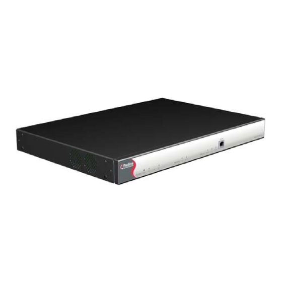
Page 16: System Overview
80 km in clear line of sight (LOS) conditions. Figure 2: AN-50e terminal The AN-50e system is a Class A digital device for use in a commercial, industrial or business environment. The system is equipped with dynamic frequency selection (DFS) to detect... - Page 17 CIR levels and priorities. With the support of CIR, the service provider can offer different grades of service to each end user in a controlled manner based on their service level agreements or contracts. 70-00033-02 Proprietary Redline Communications © 2004 November 2004 Page 17 of 96...
- Page 18 AN-50e user manual 70-00033-02 Proprietary Redline Communications © 2004 November 2004 Page 18 of 96...
-
Page 19: Physical Description
- Supplies power to the radio - Transmits control information to the radio - Receives status information from the radio - Exchanges data traffic with other communicating Systems 70-00033-02 Proprietary Redline Communications © 2004 November 2004 Page 19 of 96... -
Page 20: Ethernet Section
Table 2: terminal LAN Ethernet Port Pinout Jack Pin Function Rx + Rx - Tx + Tx - Warning: Connecting a telephone cable to the Ethernet interface will cause damage to the terminal. 70-00033-02 Proprietary Redline Communications © 2004 November 2004 Page 20 of 96... -
Page 21: System Section
Fault LED The Fault LED lights solid red when a serious fault is detected within the system. 70-00033-02 Proprietary Redline Communications © 2004 November 2004 Page 21 of 96... - Page 22 AN-50e user manual Sync LED The Sync LED lights solid green when the terminal clock is synchronized with the external GPS clock (future release). 70-00033-02 Proprietary Redline Communications © 2004 November 2004 Page 22 of 96...
-
Page 23: Time Synchronization Port
This port is currently disabled, and will be enabled in a future release. 4.1.7 Grounding Connection A ground lug connection terminal is located on the back of the AN-50e system. Correct grounding is very important for safe operation of wireless equipment. Refer to the installation section for additional information. -
Page 24: Antenna
The transceiver RF port (female N-type connector) is for sending/receiving the RF signal to/from the transceiver. A short coaxial cable is provided to connect the antenna to the transceiver. 70-00033-02 Proprietary Redline Communications © 2004 November 2004 Page 24 of 96... -
Page 25: Mounting Bracket
A mounting bracket is provided with the system. The vertical mount bracket can accommodate 1 ¾" to 4 ½" (4.45 cm to 11.45 cm) OD masts for many commercial tower installations. 70-00033-02 Proprietary Redline Communications © 2004 November 2004 Page 25 of 96... - Page 26 AN-50e user manual 70-00033-02 Proprietary Redline Communications © 2004 November 2004 Page 26 of 96...
-
Page 27: System Installation
- DC Power Cable (DC option only) - Miscellaneous: - 19" mounting brackets (terminal) A complete list of items included in the system is available on the packing list included with the system. 70-00033-02 Proprietary Redline Communications © 2004 November 2004 Page 27 of 96... -
Page 28: Site Planning
IF port cable RF port cable Antenna aiming directions (site path survey) IF port cable (supplied) Customer Antenna mast supplied Building ground connection Items Grounding wire Waterproofing material for connections 70-00033-02 Proprietary Redline Communications © 2004 November 2004 Page 28 of 96... -
Page 29: Master System Settings
Automatic Transmit Power Control Enable function. Adaptive Check this box to enable adaptive modulation mode. Modulation Radio Check this box to enable the radio transmitter. Enable 70-00033-02 Proprietary Redline Communications © 2004 November 2004 Page 29 of 96... -
Page 30: Remote-End System Settings
Automatic Transmit Power Control Enable function. Adaptive Check this box to enable adaptive modulation mode. Modulation Radio Check this box to enable the radio transmitter. Enable 70-00033-02 Proprietary Redline Communications © 2004 November 2004 Page 30 of 96... -
Page 31: General Site Survey
The wireless system also supports installation in non-line-of-sight (NLOS) conditions. A satisfactory multipath RF signal can often be obtained by directing each antenna towards a structure in sight of both communicating wireless systems. 70-00033-02 Proprietary Redline Communications © 2004 November 2004 Page 31 of 96... -
Page 32: Figure 9: Antenna Mounting Locations
If the building must be penetrated to run the IF cable, it is important to verify that building blueprints and/or drawings are up to date and accurate, and that all permissions are obtained for the required modifications. 70-00033-02 Proprietary Redline Communications © 2004 November 2004 Page 32 of 96... -
Page 33: Install The An-50E Terminal
Important: The wireless parameters should be set before the IF cable is connected to the terminal. This will avoid interference with other wireless devices located in the area. 70-00033-02 Proprietary Redline Communications © 2004 November 2004 Page 33 of 96... -
Page 34: Power
This procedure is applicable for the first-time setup of a new terminal, or if the factory default parameters have been restored using the front panel reset or through the network controls. 70-00033-02 Proprietary Redline Communications © 2004 November 2004 Page 34 of 96... -
Page 35: Setup Pc Address
Figure 11: System Address in Browser Address Bar The login screen will be displayed. Login by entering 'admin' for the User Name and Password. Figure 12: User Name And Password Dialog 70-00033-02 Proprietary Redline Communications © 2004 November 2004 Page 35 of 96... -
Page 36: Ethernet Settings
Control function. This feature will automatically adjust the power level of the remote-end system. Adaptive Modulation: Check this box to enable adaptive modulation mode. Radio Enable: Check this to enable the radio transmitter. 70-00033-02 Proprietary Redline Communications © 2004 November 2004 Page 36 of 96... -
Page 37: Install The Transceiver And Antenna
The transceiver can now be mounted to the bottom of the bracket. The transceiver is secured by two tabs located on the bottom of the bracket. Refer to the following illustration. 70-00033-02 Proprietary Redline Communications © 2004 November 2004 Page 37 of 96... -
Page 38: Mounting The Antenna
2. Connect the IF cable to the transceiver. Ensure that the cable droops downward from the transceiver to facilitate water runoff. The connector should be tightened finger-tight and then tightened an additional 1/8 of a turn. Properly weatherproof the connection. 70-00033-02 Proprietary Redline Communications © 2004 November 2004 Page 38 of 96... -
Page 39: Weatherproofing Procedure
2. Use mastic putty and work this in well around the connector and the body of the radio. Continue to work the putty to make a watertight seal. 1. The connection is now weatherproof. Figure 15 Waterproofing Outdoors Connections 70-00033-02 Proprietary Redline Communications © 2004 November 2004 Page 39 of 96... -
Page 40: Antenna Alignment
This procedure should be repeated for both the elevation and azimuth at each end of the link. 70-00033-02 Proprietary Redline Communications © 2004 November 2004 Page 40 of 96... -
Page 41: Using The Web Interface
Figure 16: On-Screen Menu The administrator (admin) has unrestricted access to all screens. All other users have restricted access. See the following table for details. 70-00033-02 Proprietary Redline Communications © 2004 November 2004 Page 41 of 96... -
Page 42: Table 9: Web Screens
System Password Change your login password. Table 10: Default System Users Username Default Description Password admin admin Access to all screens. user user Access restricted to monitoring screens. 70-00033-02 Proprietary Redline Communications © 2004 November 2004 Page 42 of 96... -
Page 43: System Monitoring Screens
System Details: Specifies the location, telephone number and/or contact information. Hardware Revision: Indicates the hardware revision level for this terminal. Outdoor Unit Type: Indicates the transceiver model number. 70-00033-02 Proprietary Redline Communications © 2004 November 2004 Page 43 of 96... - Page 44 Yes - RF link has been successfully established with the remote-end terminal. No - RF link has not been established with the remote-end terminal. Uncoded Burst Rate [Mb/s]: The actual current uncoded burst rate for the link. 70-00033-02 Proprietary Redline Communications © 2004 November 2004 Page 44 of 96...
-
Page 45: System Status
Important: For each set of Systems, only one terminal must be designated Master. RF Channel Frequency: Center frequency of the channel in use. Tx Power: Transmit power level. Cable Attenuation: Attenuation of the 800 MHz signal over the IF cable. 70-00033-02 Proprietary Redline Communications © 2004 November 2004 Page 45 of 96... -
Page 46: Ethernet Lan Statistics
MAC scheduler to repeat transmission of the lost packets. Tx Packets: Discarded: Total number of transmitted wireless packets discarded by the remote-end terminal, due to degradation in the RF link. 70-00033-02 Proprietary Redline Communications © 2004 November 2004 Page 46 of 96... - Page 47 AN-50e user manual Statistics Control Button: Reset Statistics: Click this button to zero the counters for the Wireless and Ethernet LAN Statistics displayed on this page. 70-00033-02 Proprietary Redline Communications © 2004 November 2004 Page 47 of 96...
-
Page 48: System Logs Screen
Change Password: System Password screen. Send Options Key: AN-50e Options screen Refer to section 7: Diagnostics and Troubleshooting on page 65 for a detailed description of all event messages. 70-00033-02 Proprietary Redline Communications © 2004 November 2004 Page 48 of 96... -
Page 49: System Configuration Screens
Errors in these fields will result in the inability to establish a communication link. Please read carefully to ensure a quick, trouble-free deployment. 70-00033-02 Proprietary Redline Communications © 2004 November 2004 Page 49 of 96... -
Page 50: Figure 21: System Configuration Screen - Ethernet Settings
Flow Control Enable: Check this box to enable flow control on the terminal. The Flow control feature enables the terminal to request other Ethernet devices to pause transmission during busy periods. 70-00033-02 Proprietary Redline Communications © 2004 November 2004 Page 50 of 96... - Page 51 'Configure SNMP' beside the checkbox displays the SNMP Configuration screen. See section 6.4.3: SNMP Settings on page 63 for additional information on setting up SNMP for the AN-50e. 70-00033-02 Proprietary Redline Communications © 2004 November 2004 Page 51 of 96...
-
Page 52: Figure 22: System Configuration Screen - Wireless Settings
20 MHz or more. Note: Availability of frequency bands listed in the following tables is based on the factory entered option key. Refer to the tables on the following page. 70-00033-02 Proprietary Redline Communications © 2004 November 2004 Page 52 of 96... -
Page 53: Table 11: Ce: Rf Channel Frequencies
Following an interval of thirty minutes, the same channel is monitored for one minute and if there are no DFS triggering events, the system resumes normal operation. If DFS trigger conditions are still detected, operation is suspended 70-00033-02 Proprietary Redline Communications © 2004 November 2004 Page 53 of 96... -
Page 54: Table 14: Max. Operational Power Per Channel (In Dbm) Vs. Modulation
ATPC Enable: Check this box to enable the ATPC function. The master-end system will automatically adjust the Tx level of both the master-end and remote- end systems to optimize the system performance. 70-00033-02 Proprietary Redline Communications © 2004 November 2004 Page 54 of 96... - Page 55 Only valid if Link Length Mode is set for Manual. General Antenna Alignment: Check this box to enable the antenna alignment audible tone generator in the transceiver. Radio Enable: Check this box to enable the radio transmitter. 70-00033-02 Proprietary Redline Communications © 2004 November 2004 Page 55 of 96...
- Page 56 Click the Save button at any time to save the current changes. System Reset: Click this button to boot the system. Resets all statistics and unsaved changes to the configuration will be lost. 70-00033-02 Proprietary Redline Communications © 2004 November 2004 Page 56 of 96...
-
Page 57: Pmp - Id Configuration And Status
Save IDs: Save all IDs (master-end system only). Clear All IDs: Clears all IDs from the the ID tables (master-end system only). This process cannot be undone. 70-00033-02 Proprietary Redline Communications © 2004 November 2004 Page 57 of 96... -
Page 58: Pmp - Link Configuration
ID is always zero. After saving the parameter on the Link Configuration screen, the AN-50e system will automatically choose a link ID other than zero. Use the ID Browser to search for a link name and the associated Link Peer MAC: Enter the MAC address of the subscriber station to register the remote unit. - Page 59 “Save ID” button in the “ID Config/Status” screen. Otherwise, all the Ids changes made since the last reboot will be lost. New ID: Save current ID configuration under a new Link Name. 70-00033-02 Proprietary Redline Communications © 2004 November 2004 Page 59 of 96...
-
Page 60: Upload Software
In this case, the operator will need to repeat the upload process. Use the System Configuration screen (section 6.3) to select the current operating version of system software. 70-00033-02 Proprietary Redline Communications © 2004 November 2004 Page 60 of 96... -
Page 61: Options Key Screen
The key is personalized to each terminal’s MAC address. Please ensure that the correct MAC address is provided when requesting a key from your local representative. Enter the key (case sensitive), ensure it is correct, and click the Activate button. 70-00033-02 Proprietary Redline Communications © 2004 November 2004 Page 61 of 96... -
Page 62: System Password Screen
Note: The original factory default passwords can be restored by depressing the front panel Reset button for more that five seconds. This will also reset the configuration to the factory default settings. The software version is not effected. 70-00033-02 Proprietary Redline Communications © 2004 November 2004 Page 62 of 96... -
Page 63: Snmp Settings Screen
Community Configuration/Trap Configuration screen will be displayed. Community Configuration: Community Name: The SNMP community name. After clicking Save, this name will appear in the drop down list on the main SNMP Configuration screen. 70-00033-02 Proprietary Redline Communications © 2004 November 2004 Page 63 of 96... -
Page 64: Figure 30: Snmp Community/Trap Settings Screen
This address may be left blank. Save: Click Save to permanently save the current parameters and return to the main SNMP configuration screen. Figure 30: SNMP Community/Trap Settings Screen 70-00033-02 Proprietary Redline Communications © 2004 November 2004 Page 64 of 96... -
Page 65: Diagnostics And Troubleshooting
Password admin Ethernet IP Address 192.168.25.2 Subnet Mask 255.255.255.0 Gateway 0.0.0.0 Wireless RF Channel Set by factory key. Tx power 14 dBm Encryption Disabled / no key 70-00033-02 Proprietary Redline Communications © 2004 November 2004 Page 65 of 96... -
Page 66: Front Panel Diagnostics
The two Wireless LEDs remain off for approximately five seconds, and then blink once. Following this sequence, all LEDs will indicate the current operational status. 70-00033-02 Proprietary Redline Communications © 2004 November 2004 Page 66 of 96... -
Page 67: Table 16: System Power Diagnostics
If the Fault LED lights solid red, it is an indication that there is a serious problem with the system software or hardware. Figure 34: Front Panel: System Fault LED 70-00033-02 Proprietary Redline Communications © 2004 November 2004 Page 67 of 96... -
Page 68: Table 17: Wireless Link Diagnostics
(i.e., the current Uncoded Burst Rate is lower than the configured Uncoded Burst Rate). If the system cannot maintain the lowest modulation scheme due to link errors, the Signal LED will turn off. 70-00033-02 Proprietary Redline Communications © 2004 November 2004 Page 68 of 96... -
Page 69: Table 18: Wireless Signal Diagnostics
Table 19: Ethernet Link/Act Diagnostics Symptom Possible Problem Solution No Ethernet Link Poor cable connection Carefully check all cable between terminal and connections. (Link/Act LED off) computer/server or between terminal and switch/router. 70-00033-02 Proprietary Redline Communications © 2004 November 2004 Page 69 of 96... -
Page 70: Table 20: Ethernet 100 Diagnostics
If the terminal LAN port is device may be operating connected to a host at 10Base-T. computer or server operating at 10Base-T, you may have to change the settings for that device. 70-00033-02 Proprietary Redline Communications © 2004 November 2004 Page 70 of 96... -
Page 71: Table 21: Ethernet Collision Diagnostics
Half Duplex. This results in CRC errors on the network device port. Incompatible Ethernet port Confirm speed and speed. duplex mode of devices. 70-00033-02 Proprietary Redline Communications © 2004 November 2004 Page 71 of 96... -
Page 72: Troubleshooting The Web Interface
Warning: performing a long reset will restore the terminal's IP address (192.168.25.2) and IP Subnet Mask (255.255.255.0) to the factory default value. 70-00033-02 Proprietary Redline Communications © 2004 November 2004 Page 72 of 96... -
Page 73: Troubleshooting The Rf
The minimum required voltage for operation is 12 VDC. See Table 24: RF Status Error Codes for a list of the thirty-two possible error codes. 70-00033-02 Proprietary Redline Communications © 2004 November 2004 Page 73 of 96... -
Page 74: Table 24: Rf Status Error Codes
Low DC PLL Error Error Over Power Voltage At High Temp. IF Cable Supply Radio Input Warning Fault No Errors No Errors No Errors No Errors No Errors 70-00033-02 Proprietary Redline Communications © 2004 November 2004 Page 74 of 96... -
Page 75: System Error Log Messages
Upgrade process failed. Likely cause is disconnected or faulty cable. 210-Error: TFTP unknown The TFTP client received an unknown message. In this message! case, repeat the upgrade process. 70-00033-02 Proprietary Redline Communications © 2004 November 2004 Page 75 of 96... - Page 76 Default SNMP configuration was loaded. 226-Error while saving SNMP SNMP configuration saving process wasn't successfully. Try configuration! again. If the problem persists, contact customer support. 70-00033-02 Proprietary Redline Communications © 2004 November 2004 Page 76 of 96...
-
Page 77: Saving System Parameters
The Test button is located in the System Configuration page. You must click the Save button at the bottom of the System Configuration screen to save these system parameter settings in the NVRAM. 70-00033-02 Proprietary Redline Communications © 2004 November 2004 Page 77 of 96... - Page 78 AN-50e user manual 70-00033-02 Proprietary Redline Communications © 2004 November 2004 Page 78 of 96...
-
Page 79: Appendix
Up to 80 km (50 mi) line-of-sight @ 48 dBm EIRP Network Services: Transparent to 802.3 services and applications Duplex Technique: Dynamic TDD (time division duplex) Wireless Transmission: OFDM (orthogonal frequency division multiplexing) 70-00033-02 Proprietary Redline Communications © 2004 November 2004 Page 79 of 96... - Page 80 EIRP levels for the region. Center frequency is dependent on region. With two lightning arrestors installed. Point-to-Point Mode only. Point-to-Multipoint mode only. Subject to change without notice. 70-00033-02 Proprietary Redline Communications © 2004 November 2004 Page 80 of 96...
-
Page 81: Dc Power Supply Cable Connections
Negative power Power Return Black Power Return Positive Power Schematics Note: DC units are not equipped with power switches and activate immediately when connected to a power source. 70-00033-02 Proprietary Redline Communications © 2004 November 2004 Page 81 of 96... -
Page 82: Antenna And Power Specifications
Note: The RF output power and selection must be professionally programmed and installed by the manufacturer or a trained professional installer for compliance with FCC requirements of maximum EIRP of 36 dBm. 70-00033-02 Proprietary Redline Communications © 2004 November 2004 Page 82 of 96... -
Page 83: T-58E Radio: Antenna Power Specifications
Note: The RF output power and selection must be professionally programmed and installed by the manufacturer or a trained professional installer for compliance with FCC requirements of maximum EIRP of 36 dBm. 70-00033-02 Proprietary Redline Communications © 2004 November 2004 Page 83 of 96... -
Page 84: T-54 Radio: Maximum Rf Power Vs. Antenna Gain
Table 30: 5.4 GHz Band RF Power vs Antenna Gain A6017 RWS A9016 RWS A6015 MTS A9014 MTS 70-00033-02 Proprietary Redline Communications © 2004 November 2004 Page 84 of 96... -
Page 85: Operational Power For T54 (Fcc)
28.5 14.0 29.0 14.5 29.5 15.0 30.0 15.5 30.5 16.0 31.0 16.5 31.5 17.0 32.0 17.5 32.5 18.0 33.0 18.5 33.5 19.0 34.0 19.5 34.5 20.0 35.0 20.5 70-00033-02 Proprietary Redline Communications © 2004 November 2004 Page 85 of 96... -
Page 86: Ptp Antenna Specifications
1.7:1 30x30 Horizontal Vertical or 48-00030 - 30 1.5:1 Horizontal Vertical or 48-00031 1.5:1 Horizontal Vertical or 48-00032 31.2 1.5:1 15.8 Horizontal Vertical or 48-00033 34.6 1.5:1 Horizontal 70-00033-02 Proprietary Redline Communications © 2004 November 2004 Page 86 of 96... -
Page 87: Cli Interface
Table 33: Console (RS-232) Port Pinout Name RS232 V.24 Description Receive Data Transmit Data System Ground V.24 column is ITU-TSS V.24 circuit name. RS232 column is RS232 circuit name. 70-00033-02 Proprietary Redline Communications © 2004 November 2004 Page 87 of 96... -
Page 88: Connecting Via Telnet
The following commands are available via Telnet and Console connections to the terminal. For online help, type ‘help <command>’ at the command prompt. Figure 41: CLI Help Screen 70-00033-02 Proprietary Redline Communications © 2004 November 2004 Page 88 of 96... -
Page 89: Table 34: Cli - General Commands
Allows testing of configuration settings for 5 minutes, after which the system reverts to the previously saved settings. To make settings permanent use 'save' command. upgrade Begin a software upload. 70-00033-02 Proprietary Redline Communications © 2004 November 2004 Page 89 of 96... -
Page 90: Table 35: Cli - General Information Commands
Important: For each set of Systems, only one terminal must be designated Master. resetstats Resets all statistics rffreq The center frequency of the channel in use rflink Yes: RF link up. No: RF link down 70-00033-02 Proprietary Redline Communications © 2004 November 2004 Page 90 of 96... -
Page 91: Table 37: Cli - System Configuration
Available options: off for miles and on for kilometers. Actual length of the path that the wave travels. macaddr Specifies the Ethernet MAC address used by the local 70-00033-02 Proprietary Redline Communications © 2004 November 2004 Page 91 of 96... - Page 92 Use 'Save' to make settings permanent . txpower Specifies the max. power level of the system ubrate Sets the desired burst rate for the link. 70-00033-02 Proprietary Redline Communications © 2004 November 2004 Page 92 of 96...
-
Page 93: Glossary Of Terms
A network point that acts as an entrance to another network. Gigahertz. 1,000,000,000 Hz, or 1,000 MHz Graphical User Interface Intermediate Frequency. Internet Protocol. See TCP/IP. Isotropic A theoretic construct of an antenna that radiates its signal 360 70-00033-02 Proprietary Redline Communications © 2004 November 2004 Page 93 of 96... - Page 94 Transmission Control Protocol/Internet Protocol The standard set of protocols used by the Internet for transferring information between computers, handsets, and other devices. TFTP Trivial File Transfer Protocol Transmitter 70-00033-02 Proprietary Redline Communications © 2004 November 2004 Page 94 of 96...
-
Page 95: Proprietary Redline Communications © 2004 November
AN-50e user manual 70-00033-02 Proprietary Redline Communications © 2004 November 2004 Page 95 of 96... - Page 96 302 Town Centre • Suite 100 • Markham, Ontario • Canada • L3R 0E8 www.redlinecommunications.com 70-00033-02 Proprietary Redline Communications © 2004 November 2004 Page 96 of 96...
Need help?
Do you have a question about the AN-50e system and is the answer not in the manual?
Questions and answers