Table of Contents
Advertisement
Operation Manual
Thank you very much for purchasing CHALLENGER
In order to use CHALLENGER correctly and safely and understand this product's capability,
please read this manual carefully.
The manual includes equipment structure, description, technical parameters, operation manual,
safety information, application of software, etc.
This manual is subject to change without notice.
Contents herein contained are believed to be correct, however, please contact us if you find
any error or something not clear enough.
Copyright 2004 Fei Yeung Union. All rights reserved.
INFINITI(极限)
FY-33VC
Version 1.0
November 15, 2004
Advertisement
Table of Contents

Summary of Contents for Challenger INFINITI
- Page 1 Operation Manual FY-33VC Thank you very much for purchasing CHALLENGER In order to use CHALLENGER correctly and safely and understand this product’s capability, please read this manual carefully. The manual includes equipment structure, description, technical parameters, operation manual, safety information, application of software, etc.
- Page 2 FY –33VC Operation manual - 2 -...
-
Page 3: Table Of Contents
FY –33VC Operation manual INDEX CHAPTER 1 SAFETY INFORMATION Important Safety Information Caution When Using Printer Guide When Using Ink Cartridge Choosing Printer Installation Place Warning, Caution and Attention CHAPTER 2 TECHNICAL PARAMETERS CHAPTER 3 EQUIPMENT ASSEMBLY AND ADJUSTMENT Assemble Printer Attention before Turning on FY-33VC Port of printer Connect with power... -
Page 4: Important Safety Information
FY –33VC Operation manual Chapter 1 Safety information 1.1 Important Safety Information Before use your CHALLENGER FY-33VC InkJet Digital Printer, please read following safety information. Pay attention to the cautions on the Printer. • Do not block the hole on the cover. -
Page 5: Choosing Printer Installation Place
FY –33VC Operation manual 1.4 Choosing Printer Installation Place • Put printer at a horizontal and stable place with enough space; otherwise, the Printer may not work properly. • Don’t leave Printer at a place where temperature and humidity change severely. Avoid direct sunlight, strong light or heat. -
Page 6: Technical Parameters
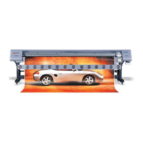
FY –33VC Operation manual Chapter 2 Technical Parameters Figure2-1 Printer Outlook Product Model FY-33VC Print Technique Xaar 126 piezo head, 12 heads inside 200dpi、400dpi Resolution Color Quality Photo effect including 2 levels: Basic and High Quality Max Media Width 3300mm Max Printing Width 3250mm Min Printing Size... - Page 7 FY –33VC Operation manual AC 100 - 240 V, 50HZ/60HZ Input Voltage (Heating voltage can be set to be manual setup by an engineer; Controlling voltage is auto setup.) Voltage for the Feeding and AC 220V, 50HZ/60HZ(AC 110V optional) Cleaning System Control:≤...
-
Page 8: Equipment Assembly And Adjustment
FY –33VC Operation manual Chapter 3 Equipment Assembly and Adjustment 3.1 Assemble Printer The whole packaging equipment is easy to assembly. 1. Please assemble supporter to a horizontal, clean and proper work area, tighten all screws on the supporter to insure safety and stability; 2. -
Page 9: Attention Before Turning On Fy-33Vc
FY –33VC Operation manual Figure 3-3 Print head frame 1—Up screw 2—Left screw 3—Right screw Method: Loosen Up and Left Screw, then remove Right Screw Insert Xaar print head 126 downwards Put on Right Screw and tighten all three screws ★... -
Page 10: Port Of Printer
FY –33VC Operation manual 4. Requirement for computer In order to avoid problems caused by computer, please choose high quality computer or brand computer such as DELL or IBM, etc. 3.3 Port of Printer USB 2.0 Connect printer’s USB and computer’s USB directly. Find driver for USB at UsbInstalFile/Try Setup under printer’s driver. - Page 11 FY –33VC Operation manual Chapter 4 Equipment Structure and Accessory Figure 4-1 Front View Figure 4-2 Media feeding system - 11 -...
- Page 12 FY –33VC Operation manual Figure 4-3 Media feeding system Figure 4-4 Print head Unit - 12 -...
- Page 13 FY –33VC Operation manual Figure 4-5 Power and cable socket Figure 4-6 Ink pumping, filter and valves - 13 -...
- Page 14 FY –33VC Operation manual Figure 4-7 Assistant ink tanks Figure 4-8 Cleaning operation panel Print head:8 piezo print heads Media:A wide range of media available Printing Platform:Platform for printing Power Switch:Turn on/off printer Press Roller Control Pole:Control press roller up / down for media feeding LCD Control Panel:Set up and execute function and mode Heating board:Heat media to dry the ink on the media - 14 -...
- Page 15 FY –33VC Operation manual Electric tank: Used to settle circle board Main Ink tanks:Total C, M, Y, K 4 colors, 1000ml/color Waste Ink Tank: Collect the waste ink during cleaning 11. Media Auto-feeding sensor: Control media feeding motor running 12. Media feeding motor:Roller driver 13.
-
Page 16: Usage Of Xaar Printer
FY –33VC Operation manual Chapter 5 Usage and Maintains of print head 5.1 Usage of Xaar Printer 1—Print head 2—In tube 3—Out tube 4—Cap 5—Fitting Figure 5-1 Print head 1、Flush humectants out of print head To moisturize print head, lots of humectants are injected into the head before it is used. The humectants must be flushed out for the first using. - Page 17 FY –33VC Operation manual the Out tube; positive-pressure clean to fill the head with ink till ink streams out from nozzles. During the process air is extruded completely from the head. 3、Moisturize print head surface After extruding air from the head, cover the Cap on the Out tube. Positive-pressure clean again until ink streams out of the nozzles, then scrub the head surface with a dry clean stick to form a protecting layer of ink on the head surface.
-
Page 18: Basic Panel Operation
Basic Operation After the printer is power on, X motor self-tests first and then Y motor. After self-testing, carriage goes back to the original position. You will see the following information displayed on the LCD screen: /// CHALLENGER • Mark with machine model •... -
Page 19: Function Description In Details
FY –33VC Operation manual the menu arrow (that is the first line on menu), press ENTER key, and submenu will be displayed. For example, when the arrow point to “1.Moving system”, press ENTER key, and it will display on the LCD screen as follows: “M1”... - Page 20 FY –33VC Operation manual Press ENTER to execute test printing. (It is same to press FUN on JAM TEST the OFFLINE mode.) After pressing ENTER, LCD displays as below: MENU -> Moving Test M3-1 Press <FUNC> to run Moving test and Press <ESC> Test OFFLINE to stop...
-
Page 21: Printing Steps
4.Options Offline mode Online mode 6. Trim the pattern for printing, and save it in computer. Open CHALLENGER RIP. 8. Create new file. 9. Read the pattern for printing. 10. Adjust the position, size, property, and resolution of the pattern. - Page 22 Select BID or single direction printing. BID has higher efficiency than single direction. 4) Click“color tune”to activate following dialogue box. Note: Details of the functions above and others referred to the CHALLENGER RIP Manual 12. Click “Printing Project” to print.
-
Page 23: Description Of Ink Supply, Cleaning System And Board
FY –33VC Operation manual Chapter 7 Description of Ink Supply, Cleaning system and board Ink Supply and Cleaning System Figure 7-1 Ink Supply and Cleaning System ( Right Side) 1. Main Tank C 2. Main Tank M 3. Main Tank Y 4. -
Page 24: Assistant Board
FY –33VC Operation manual Figure 7-3 Ink Supply and Cleaning System(Seen from Back) 1. Sub Tank C 2. Sub Tank M 3. Safety Tank 4. Sub Tank Y 5. Sub Tank K 6. Floating Switch (in sub-tank) 7. Ink in Tube 8. - Page 25 FY –33VC Operation manual 1—Reset 2—Positive pressure clean 3--Light Ink Supply and Cleaning Operation Board is connected to assistant board for ink supplement and print head cleaning. Press “Restoration” and “Cleaning” to execute. - 25 -...
-
Page 26: Ink Supply System
FY –33VC Operation manual Chapter 8 Ink Supply System 8.1 Summary This ink supply system can control automatically several pumps at the same time and provides protect function. Isolated ink supply system is easy for operation. 8.2 System Diagram Ink tube Sub-tank Print head Filter... -
Page 27: Intelligent Detection Function
FY –33VC Operation manual Control system before starting the following operations. As soon as the printer’s connected with power, system detects floating switch signal automatically, and then ink will be filled into sub-tank. When ink channel lacks of ink, system will start the pump automatically; and indicator lighten. After the floating switch senses the ink, the pump will continue to work for a little period and then stop;... -
Page 28: Cleaning System
FY –33VC Operation manual Chapter 9 Cleaning System 9.1 Summary This type of printer use cleaning methods as positive pressure cleaning, you execute cleaning before printing, during printing or idle for a long time. 9.2 System Diagram Air Filter channel Print head Assistant Ink Tank... -
Page 29: Operation Description
FY –33VC Operation manual 9.4 Operation Description Move print head to cleaning position, Press “Ink” button on Cleaning Operation Board to launch positive pressure cleaning. Release the button to stop cleaning. Turn on Illuming Switch to lighten and check the ink drop. -
Page 30: Heating System
FY –33VC Operation manual Chapter 10 HEATING SYSTEM 10.1 Summary This heating system can adjust temperature based on different PVC material and surrounding. It can adjust the temperature automatically to keep temperature constant. Customer can have satisfactory printing effect. 10.2 System Diagram Front heating board Temp-switch signal... - Page 31 FY –33VC Operation manual power for printer, the heating system will not work. However, there is still AC 220V inside machine. Temperature detector lies about 50cm to the right physical printing original position. Print media should cover this region when printing. After printing, make sure to turn off the two powers.
-
Page 32: Software Operation
FY –33VC Operation manual Chapter 11 Software Operation 11.1 Installation 1. Installation of Challenger RIP Software: see the RIP User’s Manual for details. a) Insert RIP CD into computer’s CD-ROM b) Run setup.exe c) Follow the instruction to finish the installation 2. - Page 33 FY –33VC Operation manual First, choose type printer. Click “Printer” menu , choose item FY-3212C/FY-3212C+/FY-33VC. 4. Then open “File” to adjust some settings. - 33 -...
- Page 34 FY –33VC Operation manual In these menus, most important is print setting. 11.2.2 Print Setting This function is to set the printing parameter, print mode, uni-direction, BID and the color of ink. Note: Usually the four colors should all be selected. Only when the engineer adjusts the position of head, one certain color is chosen to modify the printing parameter.
- Page 35 FY –33VC Operation manual After pressing “Yes”, you can see the dialogue box: Note: Press “load parameter” first to read the original data before adjusting. Meaning of this dialogue box: 1. Parameter of nozzle installation: Adjust the head position and overlapping of four colors. - 35 -...
- Page 36 FY –33VC Operation manual Printhead driving board Head 2 Head 5 Head 8 Head 11 Head 1 Head 4 Head 7 Head 10 Head 0 Head 3 Head 6 Head 9 Head 0-K3 Head 3-Y3 Head 6-M3 Head 9-C3 Vertical gap Head 1-K2 Head 4-Y2 Head 7-M2...
- Page 37 FY –33VC Operation manual K. The vertical gap between head K2 and head C1 is ensured by mechanical precision. The value of horizontal gap is K. (In above figure is 2551) L. The vertical gap between head K3 and head C1 is ensured by mechanical precision. The value of horizontal gap is L.
- Page 38 FY –33VC Operation manual EF value setting: Each Xaar126 head has its own EF value. Manufacture always provides a standard EF value, which is captured under standard condition. Users input this value at column Voltage. Usually, the printing effect is good.
- Page 39 If some of them are straight while others not, you can input the value in dialog “Important Setup\BiComp” for each print head. Note: Different speed has its own BID rectangle value. 11.4 Basic operation of RIP Refer to CHALLENGER RIP Manual. Please close the printer driver software before opening RIP. - 39 -...
Need help?
Do you have a question about the INFINITI and is the answer not in the manual?
Questions and answers