
Summary of Contents for Sunhome Tech SR1568
- Page 1 Operation Manual of Solar controller SR1568 for split solar system Version En 2015.08...
-
Page 2: Table Of Contents
Operation manual of solar controller SR1568 Contents 1. Safety information ........................4 1.1 Installation and commissioning .................... 4 1.2 About this manual ........................4 1.3 Liability waiver ......................... 4 1.4 Important information ......................5 1.5 Signal description ........................5 1.6 HMI button ..........................5 2 Overview............................ - Page 3 Operation manual of solar controller SR1568 System 10: Solar system with east/west collector fields, 1 tank, 3-ways valve loading tank in layers, loading the heating return ................24 System 11: Solar system with1 collector field, 2 tanks, 3-ways valve switch loading tank ................................
- Page 4 Operation manual of solar controller SR1568 6. Holiday function........................77 7. Software of controller upgrade ..................... 78 8. Protection function ........................80 8.1 Screen protection ......................... 80 8.2 Trouble protection ......................... 80 8.3 Trouble checking........................80 9. Quality Guarantee........................85 10.
-
Page 5: Safety Information
Operation manual of solar controller SR1568 1. Safety information 1.1 Installation and commissioning When laying wires, please ensure that no damage occurs to any of the constructional fire safety measures presented in the building. The controller must not be installed in rooms where easily inflammable gas mixtures are present or may occur. -
Page 6: Important Information
Operation manual of solar controller SR1568 into operation. 1.4 Important information We have carefully checked the text and pictures of this manual and provided the best of our knowledge and ideas, however inevitable errors maybe exist. Please note that we cannot guarantee that this manual is given in the integrity of image and text, they are just some examples, and they apply only to our own system. -
Page 7: Overview
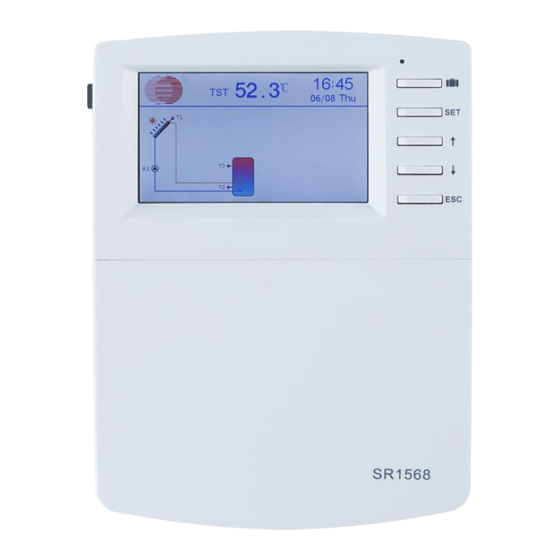
Operation manual of solar controller SR1568 2 Overview 2.1 Controller introduction TFT colorful screen display 6 * relay outputs 1 * low voltage relay output 7 * sensor inputs 1 * Grundfos Direct Sensor TM (VFS) simulation input ... -
Page 8: Installation
Operation manual of solar controller SR1568 Power supply : 100…240V ~(50…60Hz) Rated impulse voltage::2.5KV Data interface : TF (Micro SD) 485 current supply:60mA Housing:Plastic ABS Mounting:Wall mounting Indication / Display: System-Monitoring-Display, for visualization of the systems, TFT colorful display, and background illumination ... -
Page 9: Wiring Connection
Operation manual of solar controller SR1568 Put the cover on the housing. Attach with the fastening screw. 3.2 Wiring connection According to the way of installation, wire can be connected from hole A on the bottom plate or from hole B, using a suitable tool (like knife) to cut the plastic of A. - Page 10 Operation manual of solar controller SR1568 thermal energy calculation. T2~T6: NTC10K,B=3950 temperature sensor, for measuring temperature of tank and pipe. Communication port 485:ELA485, for remote control communication HK-A, HK-B:Dry connection on/off signal ports, (HK and HR simultaneously open or close, for boiler heating control) IPWM1, IPWM2, IPWM3:Signal ports for high efficiency pump, detailed connection see...
- Page 11 Operation manual of solar controller SR1568 Output terminal Input Ports L N: for power connection, L: live wire, N: zero wire, protective wire Output R1: Semiconductor relays (SCR), designed for pump speed control, Max. Current: 1A Output R2: Semiconductor relays (SCR), designed for pump speed control, Max. Current: 1A Output R3:...
-
Page 12: Tf (Microsd) Card
Operation manual of solar controller SR1568 R4~R5: When it is for control 3 ways electromagnetic valve,(3 is normally close port, 2 is normally on port ,1 is common port) When it is for control pump, (2 is normally on port, 1 is common port) ... - Page 13 Operation manual of solar controller SR1568 the data to a computer, the values can be opened and visualized, e. g. in a spreadsheet. Prepare adjustments and parameterizations on a computer and transfer them via the MicroSD card to the controller.
-
Page 14: System
Operation manual of solar controller SR1568 4. System 4.1 Overview of the available systems Page 13 of 87... -
Page 15: Description Of 23 Systems
Operation manual of solar controller SR1568 4.2 Description of 23 systems Note: auxiliary functions introduction! The system diagrams showed in this manual are used for normal solar hot water system design, for individual application, some very useful auxiliary functions are available in this controller, it makes the controller more intelligent and user friendly. -
Page 16: System 1: Standard Solar System With 1 Tank, 1 Collector Field
Operation manual of solar controller SR1568 System 1: Standard solar system with 1 tank, 1 collector field Description: The controller calculates the temperature difference between collector sensor T1 and tank sensor T2. If the difference is larger than or identical to the adjusted switch-on... -
Page 17: System 2: Solar System With 1 Tank, 1 Collector Field, 3-Ways Valve For Tank Loading In Layers
Operation manual of solar controller SR1568 System 2: Solar system with 1 tank, 1 collector field, 3-ways valve for tank loading in layers Description: The controller calculates the temperature difference between collector sensor T1 and tank base and upper sensor T2, T3. -
Page 18: System 3: Solar System With 1 Tank, East/West Collector Fields
Operation manual of solar controller SR1568 System 3: Solar system with 1 tank, east/west collector fields Description: The controller calculates the temperature difference between collector sensor T1, T0 and tank base sensor T2. If one of the differences is larger than or identical to the adjusted... -
Page 19: System 4: Solar System With East/West Collector Fields, 3-Ways Valve For Tank Loading In Layers
Operation manual of solar controller SR1568 System 4: Solar system with east/west collector fields, 3-ways valve for tank loading in layers Description: controller calculates temperature difference between collector sensor T1, T0 and tank base, upper sensor T2, T3. If any difference... -
Page 20: System 5: Solar System With East/West Collector Fields, 1 Tank, Valve-Logic Control
Operation manual of solar controller SR1568 System 5: Solar system with east/west collector fields, 1 tank, valve-logic control Description: The controller calculates the temperature difference between collector sensor T1, T0 and tank base sensor T2. If any difference is larger than or identical to the adjusted... -
Page 21: System 6: Solar System With 1 Collector Field, 1 Tank, Loading The Heating Return
Operation manual of solar controller SR1568 System 6: Solar system with 1 collector field, 1 tank, loading the heating return Description: The controller calculates the temperature difference between collector sensor T1 and tank base sensor T2. If the difference is larger... -
Page 22: System 7: Solar System With 1 Collector Field, 1 Tank, 3-Ways Valve Loading Tank In Layers, Loading The Heating Return
Operation manual of solar controller SR1568 System 7: Solar system with 1 collector field, 1 tank, 3-ways valve loading tank in layers, loading the heating return Description: controller calculates temperature difference between collector sensor T1 and tank base and upper sensor T2, T3. If any difference... -
Page 23: System 8: Solar System With East/West Collector Field, 1 Tank, Loading The Heating Return
Operation manual of solar controller SR1568 System 8: Solar system with east/west collector field, 1 tank, loading the heating return Description: The controller calculates the temperature difference between collector sensor T1, T0 and tank base sensor T2. If any difference is larger... -
Page 24: System 9: Solar System With East/West Collector Fields, 1 Tank, 3-Ways Valve Switch Collector, Loading The Heating Return
Operation manual of solar controller SR1568 System 9: Solar system with east/west collector fields, 1 tank, 3-ways valve switch collector, loading the heating return Description: The controller calculates the temperature difference between collector sensor T1, T0 and tank base sensor T2. If any difference is... -
Page 25: System 10: Solar System With East/West Collector Fields, 1 Tank, 3-Ways Valve Loading Tank In Layers, Loading The Heating Return
Operation manual of solar controller SR1568 System 10: Solar system with east/west collector fields, 1 tank, 3-ways valve loading tank in layers, loading the heating return Description: controller calculates temperature difference between collector sensor T1, T0 and tank base/upper sensor T2, T3. If any difference... -
Page 26: System 11: Solar System With1 Collector Field, 2 Tanks, 3-Ways Valve Switch Loading Tank
Operation manual of solar controller SR1568 System 11: Solar system with1 collector field, 2 tanks, 3-ways valve switch loading tank Description: controller calculates temperature difference between collector sensor T1 and tank sensor T2, T4. If any difference is larger than or... -
Page 27: System 12: Solar System With 1 Collector Field, 2 Tanks, Pump Switch Loading Tank
Operation manual of solar controller SR1568 System 12: Solar system with 1 collector field, 2 tanks, Pump switch loading tank Description: controller calculates temperature difference between collector sensor T1 and tank sensor T2, T4. If any difference is larger than or... -
Page 28: System 13: Solar System With East/West Collector Fields, 2 Tanks, 3-Ways Valve Switch Loading Tank
Operation manual of solar controller SR1568 System 13: Solar system with east/west collector fields, 2 tanks, 3-ways valve switch loading tank Description: controller calculates temperature difference between collector sensor T1, T0 and tank sensor T2, T4. If any difference is larger... -
Page 29: System 14: Solar System With 1 Collector Field, 2 Tanks, Thermal Energy Transferring Between 2 Tanks
Operation manual of solar controller SR1568 System 14: Solar system with 1 collector field, 2 tanks, thermal energy transferring between 2 tanks Description: controller calculates temperature difference between collector sensor T1 and tank sensor T2. If the difference is larger than or... -
Page 30: System 15: Solar System With 1 Collector Field, 2 Tanks, Valve Switch Loading Tank, Thermal Energy Transferring Between 2 Tanks
Operation manual of solar controller SR1568 System 15: Solar system with 1 collector field, 2 tanks, valve switch loading tank, thermal energy transferring between 2 tanks Description: controller calculates temperature difference between collector sensor T1 and tank sensor T2 or T4. If the difference is larger than or... -
Page 31: System 16: Solar System With 1 Collector Field, 1 Tank, Valve Switch Loading Tank In Layers, Thermal Energy Transferring Between 2 Tanks
Operation manual of solar controller SR1568 System 16: Solar system with 1 collector field, 1 tank, valve switch loading tank in layers, thermal energy transferring between 2 tanks Description: controller calculates temperature difference between collector sensor T1 and tank 1 sensor T2 or T3. -
Page 32: System 17: Solar System With 1 Collector Field, 2 Tanks, Pump Switch Loading Tank, Thermal Energy Transferring Between 2 Tanks
Operation manual of solar controller SR1568 System 17: Solar system with 1 collector field, 2 tanks, pump switch loading tank, thermal energy transferring between 2 tanks Description: controller calculates temperature difference between collector sensor T1 and tank 1/2‘s sensor T2 or T4. If the difference is larger... -
Page 33: System 18: Solar System With East/West Collector Fields, 2 Tanks, Pump Switch Collector, Valve Switch Loading In Layers, Energy Transferring Between 2 Tanks
Operation manual of solar controller SR1568 System 18: Solar system with east/west collector fields, 2 tanks, pump switch collector, valve switch loading in layers, energy transferring between 2 tanks Description: controller calculates temperature difference between collector sensor T1, T0 and sensor T2, T3 of tank 1. -
Page 34: System 19: Solar System With East/West Collector Fields, 2 Tanks, Thermal Energy Transferring Between 2 Tanks
Operation manual of solar controller SR1568 System 19: Solar system with east/west collector fields, 2 tanks, thermal energy transferring between 2 tanks Description: controller calculates temperature difference between collector sensor T1, T0 and sensor T2 of tank 1. If any difference is larger than... -
Page 35: System 20: Solar System With East/West Collector Fields, 2 Tanks, Valve Switch Loading Tank, Thermal Energy Transferring Between 2 Tanks
Operation manual of solar controller SR1568 System 20: Solar system with east/west collector fields, 2 tanks, valve switch loading tank, thermal energy transferring between 2 tanks Description: controller calculates temperature difference between collector sensor T1, T0 and sensor T2 of tank 1, T4 of tank 2. If any difference... -
Page 36: System 21: Solar System With 1 Collector Field, 2 Tanks, Valve Switch Loading Tank, Preheating Return Of Heating System
Operation manual of solar controller SR1568 System 21: Solar system with 1 collector field, 2 tanks, valve switch loading tank, preheating return of heating system Description: controller calculates temperature difference between collector sensor T1 and sensor T2 of tank 1, T4 of tank 2. If any difference... -
Page 37: System 22: Solar System With 1 Collector Field, 2 Tanks, Pump Switch Loading Tank, Preheating Return Of Heating System
Operation manual of solar controller SR1568 System 22: Solar system with 1 collector field, 2 tanks, pump switch loading tank, preheating return of heating system Description: The controller calculates the temperature difference between collector sensor T1 and sensor T2 of tank 1, T4 of tank 2. If any... -
Page 38: System 23: Solar System With East/West Collector Fields, 2 Tanks, Valve Switch Loading Tank, Preheating Return Of Heating System
Operation manual of solar controller SR1568 System 23: Solar system with east/west collector fields, 2 tanks, valve switch loading tank, preheating return of heating system Description: controller calculates temperature difference between collector sensor T1, T0 and sensor T2 of tank 1, T4 of tank 2. If any difference... -
Page 39: Commissioning
Operation manual of solar controller SR1568 4.3 Commissioning Before connecting the controller to the mains, ensure system is filled and ready for operation, please connecting all sensors to the input terminals, pumps or valves to the output terminals and fill the system. -
Page 40: Channel Description Of Adjustable Menu
Operation manual of solar controller SR1568 5.2 Channel description of adjustable menu Page 39 of 87... - Page 41 Operation manual of solar controller SR1568 Page 40 of 87...
- Page 42 Operation manual of solar controller SR1568 Page 41 of 87...
- Page 43 Operation manual of solar controller SR1568 Page 42 of 87...
- Page 44 Operation manual of solar controller SR1568 Page 43 of 87...
- Page 45 Operation manual of solar controller SR1568 Page 44 of 87...
- Page 46 Operation manual of solar controller SR1568 Page 45 of 87...
- Page 47 Operation manual of solar controller SR1568 Page 46 of 87...
- Page 48 Operation manual of solar controller SR1568 Page 47 of 87...
- Page 49 Operation manual of solar controller SR1568 Page 48 of 87...
- Page 50 Operation manual of solar controller SR1568 Page 49 of 87...
-
Page 51: Menu Operation Description
Operation manual of solar controller SR1568 5.3 Menu operation description Access main menu ►press “SET” button to access main menu ►Press “↑”, “↓” to select menu ►Press “SET” button to enter the submenu Access submenu ►Press “SET” button to access submenu ►Press “SET”... - Page 52 Operation manual of solar controller SR1568 ADST: Switch on/off the auto summer function When you deactivate the “auto summer function”, controller still can run, “ADST” is only referring Europe 200/84/EG, only suitable for Europe union country. Time: Set clock and time; firstly adjust hour, then minute.
- Page 53 Operation manual of solar controller SR1568 NoAux : No back-up heat source Electric : Electrical heater as heating back-up Boiler: Boiler as heating back-up T_Sensor: Select sensor for timing heating function, default sensor is T3 Timing heating Timing heating function is independent of solar system;...
- Page 54 Operation manual of solar controller SR1568 Boiler connection diagraph: Switch on/off signal When boiler as back-up device is selected, then back-up heating (HK and HR) is controlled by tank’s sensor T3, if the T3’s value is lower than the switch-on temperature of back-up heating, the output relay HK and HR is switched on, when T3 is higher than the switch-off temperature of back-up heating, the output relay HK and HR is switch-off.
- Page 55 Operation manual of solar controller SR1568 TEMPRE (temperature controlled DHW circulation within the preset 3 time sections) This controller provides an output for running DHW circulation pump, which can be controlled by a temperature, at this case, an extra circuit pump (connect to the output REL option) and an extra temperature sensor mounted on the hot water return pipe (connect to the input which set under T_sensor menu ) should be installed in the system.
- Page 56 Operation manual of solar controller SR1568 Each system has pre-programmed options and adjustments which can be activated or changed respectively if necessary. Select the system first (1-23 systems available) LOAD (2) DT Temperature difference The controller works as a standard differential controller. If the temperature reaches or exceeds the switch-on temperature difference, the pump switches on.
- Page 57 Operation manual of solar controller SR1568 If the temperature difference reaches the adjusted set temperature difference, the pump speed increases by one step (10%). The response of the controller can be adapted via the parameter RISE. If the difference increases by the adjustable rise value RIS, the pump speed increases by 10% until the maximum pump speed of 100% is reached.
- Page 58 Operation manual of solar controller SR1568 LOL (2) CEM Collector emergency shutdown When the collector temperature exceeds the adjusted collector emergency temperature, Then solar pump (R1 / R2) switches off in order to protect the system components against overheating (collector emergency shutdown). If the maximum collector temperature is...
- Page 59 Operation manual of solar controller SR1568 temperature, but only up to 95° C (emergency shutdown of the tank), and Emerj is displayed, system stops. If the collector cooling is active, Cooling is displayed. This function is only available if the system cooling function and the heat transfer function are not activated.
- Page 60 Operation manual of solar controller SR1568 OTCO Tube collector function This function is used for improving the switch-on behavior in systems with non-ideal sensor positions (e. g. with some tube collectors). This function operates within an adjusted time section. It activates the collector circuit pump for an adjustable runtime between adjustable pauses in order to compensate for the delayed temperature measurement.
- Page 61 Operation manual of solar controller SR1568 Adjustment for standard pump with speed control: PULS : Burst control via semiconductor relay Adjustment for high-efficiency pump (HE pump) • PSOL: PWM profile solar pump • PHEA: PWM profile heating pump •...
- Page 62 Operation manual of solar controller SR1568 Priority logic Priority logic can be used in 2-tanks systems or systems with tank loading in layers only; it determines how the heat is divided between the tanks. Several different priority logic types can be selected: ...
- Page 63 Operation manual of solar controller SR1568 then system is switched to load the subordinate tank. This function is suitable for 2 tanks’ system. OSE Spread loading option In systems with 2 pumps, a spread loading function OSE can be activated, as soon as the adjustable spread temperature difference DTSE between the collector and the priority tank is reached, the second tank will be loaded in parallel unless it is blocked.
- Page 64 Operation manual of solar controller SR1568 Different cooling functions can be activated: system cooling, tank cooling and external radiator heat transfer. OSYC System cooling The system cooling function aims to keep the solar system operational for a longer time. The function overrides the maximum tank temperature to provide thermal relief of the collector field and the heat transfer fluid on hot days.
- Page 65 Operation manual of solar controller SR1568 Heat transfer by variant pump: If the collector temperature or tank temperature reaches the adjusted switch-on temperature, the allocated relay for pump is energized with 100 %; if the collector temperature falls by 5 K below the adjusted collector over-temperature, the relay will be switched off.
- Page 66 Operation manual of solar controller SR1568 Note: The adjustable collector over-temperature value OTST is blocked against the collector emergency temperature CEM by 10 K. This function will only be available when the collector cooling function and the system cooling function are deactivated.
- Page 67 Operation manual of solar controller SR1568 The return preheating function can be used for transferring heat from a heat source to the heating circuit return. The relay (system-dependent) is energized when both switch-on conditions are fulfilled: • The temperature difference between the sensors of tank and sensor of the heating circuit return has exceeded the switch-on temperature difference.
- Page 68 Operation manual of solar controller SR1568 increase or decrease by the rise value, the pump speed will be adjusted by 10 %. The switch-on hysteresis is -5 K. BYPR Solar circulation bypass function In some cases, it is good application to combine a temperature controlled bypass circuit into the solar circuit.
- Page 69 Operation manual of solar controller SR1568 TIMER (Timer function) Timer function can trigger controller’s output port at the preset time; therefore, an available output is needed. Icon displays on the screen, it means the timer function is activated. Icon displays on the screen, it means timer function is in operation.
- Page 70 Operation manual of solar controller SR1568 For control and service work, the operating mode of the relays can be manually adjusted. For this purpose, select the adjustment menu MAN (for R1, R2, R3, R4, R5, HR) to set manual output “On/OFF”.
- Page 71 Operation manual of solar controller SR1568 The monitoring period PDIS starts as soon as the temperature at the allocated sensor falls below the disinfection temperature TDIS, once the monitoring period PDIS ends, disinfect period SDIS starts, the allocated reference relay activates the after-heating, and SDIS disinfect time count down “Disinfect 15”...
- Page 72 Operation manual of solar controller SR1568 The heat quantity measurement can be carried out in 2 different ways: Fixed flow rate ( with flow meter) With Granados flow rotor VFS. Heat quantity measurement with fixed flow rate value The heat quantity measurement calculation (estimation) uses the difference between the flow T1 and return T6 temperatures and the entered flow rate (at 100 % pump speed).
- Page 73 Operation manual of solar controller SR1568 Adjust the antifreeze type and concentration of the heat transfer fluid under menu MEDT and MED% For the systems with 2 collector fields, sensor should be installed on the general flow and return pipe for heat quantity measurement.
- Page 74 Operation manual of solar controller SR1568 If the shutdown option has been activated for the flow rate monitoring function, the tank being loaded will be blocked for any further loading until the error message has been acknowledged. The next tank free for loading will be loaded instead, if possible. When the error message has been acknowledged, the monitoring function will be active again.
- Page 75 Operation manual of solar controller SR1568 If the shutdown option has been activated for the low pressure monitoring function, the solar system will be shut down as well in the case of a fault condition. When the pressure reaches or exceeds the adjustable switch-off pressure value, the system is switched on again.
- Page 76 If wrong operated, just repower the controller and redo according to above steps. Note: The controller will only find a file named "SR1568.bin" on the root directory of MicroSD memory card for the firmware update, find the file named BmpList.txt to update the pictures.
- Page 77 Operation manual of solar controller SR1568 then card can be taken out. Formatting the MicroSD card ( FORM) Select the menu item FORM, “YES” displays, press “SET” to move the cursor to “YES”, continues press “SET” “ WAIT” displays, formatting order starts to run, it lasts ca. 10 seconds, running finished, “SUCC”...
-
Page 78: Holiday Function
Operation manual of solar controller SR1568 By means of the reset function, all adjustments can be set back to the factory settings. Doing follow below description. Switch-off the power to controller Hold “ESC” button, reconnect power, after 3 seconds, release “ESC” button, then controller recovery to the factory set password (default password 0000), and reset the password according to requirement. -
Page 79: Software Of Controller Upgrade
Update for new firmware SR1568 9-Aug-2015 Ji GenJun 1) Please copy the files like SR1568.bin,*.dta to the root directory of Micro SD Card. See screen snap below. A. Switch-off the power and insert card to the controller, then hold down button “HOLIDAY”, and reconnect power to controller. - Page 80 Operation manual of solar controller SR1568 2) Press “SET” button to confirm upgrade, If there are updated file in card, screen will show red words “Updating Picture”, blue word “working” will flash at the top of screen. 3) When upgrading is finished (depending on the size and quantity of files, running time is different), “Updating Picture OK”...
-
Page 81: Protection Function
Operation manual of solar controller SR1568 7) If the screen shows “Update Failure! Please try again! ”, please check the files in TFCard, and do again following the step 1 above descript or call our technician for support. FAQs: String in screen... - Page 82 Operation manual of solar controller SR1568 On the control panel, LED lamp flashes and icon flashes too. Sensor errors, press “↑” “↓” button, sensor number shows on the screen, red one means fault sensor Open Short Wire is open, Wire is short,...
- Page 83 Operation manual of solar controller SR1568 Pump is overheated, but no heat transfer from the collector to the tank, flow and return have the same temperature; perhaps also bubbling in the pipes Air or gas bubbles in the system? Vent the system; increase the...
- Page 84 Operation manual of solar controller SR1568 The temperature difference between tank and collector increases enormously during operation; the collector circuit cannot dissipate the heat. Collector circuit pump defective? Check / replace it Heat exchanger calcified? Yes Decalcify it Heat exchanger blocked?
- Page 85 Operation manual of solar controller SR1568 Tanks cool down at night. Collector circuit pump runs during the night? Check controller Collector temperature at night is higher than the outdoor temperature. Check the non-return valves in the flow and the return pipe for functional efficiency.
-
Page 86: Quality Guarantee
Operation manual of solar controller SR1568 9. Quality Guarantee Manufacturer provides following quality responsibilities to end-users: within the period of quality responsibilities, manufacturer will exclude the failure caused by production and material selection. A correct installation will not lead to failure. When a user takes incorrect... - Page 87 Operation manual of solar controller SR1568 SR802 connection diagram Protection switch Tank Electrical PA Protection heater flexible pipe Controller Connect heater PA Protection output of controller flexible pipe Relay Note: Switch-off power, and perform by profession installer. Page 86 of 87...
Need help?
Do you have a question about the SR1568 and is the answer not in the manual?
Questions and answers
⸻ Hi, could you please explain how the PWM pump works in System 11? Is the relay output R1 always on, with speed regulation controlled via the PWM output? Also, is this pump suitable for this controller? If so, which mode should I use?
Hi, I need a wire layout for the pressure and flow sensor, because I don't have a power supply.