Table of Contents
Advertisement
Advertisement
Table of Contents

Summary of Contents for Fixturlaser GO Pro
- Page 1 Fixturlaser GO Pro user`s MANUAL...
-
Page 3: Table Of Contents
Shaft Alignment Vertical Machines Machine Defined Data Softcheck Target Values 10.1 Memory Manager 11.1 Global Settings 12.1 Display Unit GO Pro D 13.1 Wireless Transceivers 14.1 Technical Specification 15.1 GO Pro D Fixturlaser GO Pro Manual 2 edition September 2011... - Page 4 Fixturlaser GO Pro Manual 2 edition September 2011...
-
Page 5: Introduction
Congratulations on your choice of the functions and equipment that may be Fixturlaser GO Pro! available in a Fixturlaser GO Pro We are convinced that you have made system; the ones that are available in the right decision and we hope the... - Page 6 The software may not Elos Fixturlaser AB or its suppliers shall, be removed from the hardware. to the maximum extent permitted by The software contained in the system is...
-
Page 7: Declaration Of Conformity
Standard/Test report/Technical Type designation(s)/Model no(s) construction file/Normative 1-0875 Fixturlaser GO Pro document Emission: EN 61000-6-3:2007. Immunity: EN 61000-6-2:2005, EN 61000-4-2, -3. ISO9001:2008 Ref. No/ Issued by: DNV Certification AB Certification No. 2009- SKM-AQ-2704 / 2009-SKM-AE-1419. Fixturlaser GO Pro Manual 2 edition... - Page 8 (1) this device may not cause harmful interference, and (2) this device must accept any interference received, including interference that may cause undesired operation. Hans Svensson, Managing Director Additional information The product was CE-marked in 2010. Fixturlaser GO Pro Manual 2 edition...
-
Page 9: Safety
Never stare directly into the laser LASER PRECAUTIONS transmitter. Fixturlaser GO Pro uses laser diodes Never shine the laser directly into with a power output of < 1.0 mW. The anyone else‟s eyes. - Page 10 POWER SUPPLY Fixturlaser GO Pro is powered by three 1.5V LR-14 (C) Alkaline batteries or by corresponding 1.2V NiMH HR-14 Rechargeable Nickel Metal Hydride cells. Only use high performance alkaline batteries. Remove batteries when the system is stored for prolonged periods of time.
- Page 11 WIRELESS TRANSCEIVER Handle any batteries with care. The GO Pro system is fitted with Batteries pose a burn hazard if handled Bluetooth wireless transceivers. improperly. Do not disassemble and keep away from heat sources. Handle Make sure that there are no restrictions...
- Page 12 Fixturlaser GO Pro Manual 2 edition...
-
Page 13: Care
For the best possible function, the laser diode apertures, detector surfaces and connector terminals should be kept free from grease or dirt. The display unit should be kept clean and the screen surface protected from scratches. Fixturlaser GO Pro Manual 2 edition... - Page 14 The chains on the V-block fixtures are delivered dry. If the system is used in highly corrosive environments, the chains should be oiled. Fixturlaser GO Pro Manual 2 edition...
-
Page 15: Main Menu
MAIN MENU The Fixturlaser GO Pro is provided with different programs for specific purposes. Press the red On/Off button to start the system and the Main Menu appears. Here you can select the program that you want to use. In the Main Menu you will also find the Memory Manager and Global Settings. -
Page 16: Shaft Alignment Horizontal
APPLICATION PROGRAMS SYSTEM FUNCTIONS Shaft Alignment Horizontal Global Settings Machines Shaft Alignment Vertical Machines Machine Defined Data Wireless indicator Battery indicator MEMORY MANAGER Memory Manager Fixturlaser GO Pro Manual 2 edition... -
Page 17: Shaft Alignment Vertical
PC for table is available in the system. further documentation purposes. The Fixturlaser GO Pro system has two measuring units that are placed on each shaft by using the fixtures supplied with the system. After rotating the shafts... - Page 18 Check coupling assembly and Are there any restrictions for loosen the coupling bolts. mounting the measuring system? Check soft foot conditions. Is it possible to rotate the shafts? Mechanical looseness. What shim size is needed? Fixturlaser GO Pro Manual 2 edition...
- Page 19 Check coupling and shaft run-out. Pipe work strain. Coarse alignment. Check coupling gap (axial alignment). Fixturlaser GO Pro Manual 2 edition...
- Page 20 “S” on the stationary machine. The sensors shall be assembled on their V-block fixture, and placed on each side of the coupling. Hold the V-block fixture upright and mount it on the shafts of the measurement object. Fixturlaser GO Pro Manual 2 edition...
- Page 21 Secure tighten. If the shaft diameter is too its position by locking both clamping large the chains can be extended with devices on the back of both units. extension chains (optional). Fixturlaser GO Pro Manual 2 edition...
- Page 22 Always let the cables from the wireless distances. communication devices stay connected NOTE: Make sure that the adjustment to the sensor units. screw is secured with the locking nut after adjustment. Fixturlaser GO Pro Manual 2 edition...
- Page 23 Horizontal Shaft Alignment icon in the Main Menu and press OK. When the program is started, a tolerance table will be displayed first. Select tolerance and press OK. Go to settings for selecting settings. Fixturlaser GO Pro Manual 2 edition...
- Page 24 Machine alignment should be carried out within the manufacturer‟s tolerances. The table provided in Fixturlaser GO Pro can be helpful if no tolerances are specified. The suggested tolerances can be used as a starting point for developing in-house tolerances when the machinery manufacturer‟s...
- Page 25 OK or scroll to the right. Enter tolerance for the angle values and press OK or scroll to the right. Enter tolerance for the offset values and press OK or scroll to the right. Fixturlaser GO Pro Manual 2 edition...
- Page 26 OK. Select normal or long sampling time. To change sampling time, select the sampling time icon and press OK. Select normal or long sampling time with the left/right buttons and press OK. Fixturlaser GO Pro Manual 2 edition 6.10...
- Page 27 Opens window for adding a new machine with defined data to Machine Defined Data. Entered data, such as distances, Target Values and tolerances, will be saved. Fixturlaser GO Pro Manual 2 edition 6.11...
- Page 28 Turns off the inclinometers. Measurement with disabled inclinometers is described at the end of this chapter. Exit Exits the Settings and returns to the application. Fixturlaser GO Pro Manual 2 edition 6.12...
- Page 29 M-sensor and the first pair of feet and the distance between the first and the second pairs of feet. The screen displays the movable machine. Select the dimension boxes to enter dimensions. Measure and enter dimensions. Fixturlaser GO Pro Manual 2 edition 6.13...
- Page 30 TIP: The larger the angle over which the three points are measured, the fewer moves and repeat measurements will have to be made. Minimum angle between readings is 45°. A green flashing arrow suggests suitable measurement positions. Fixturlaser GO Pro Manual 2 edition 6.14...
- Page 31 Green sector show permitted positions. Select the register icon and Red sector show forbidden positions. press OK. The Register icon is not shown if the This registers the first rotation is less than 45°. reading. Fixturlaser GO Pro Manual 2 edition 6.15...
- Page 32 This registers the third reading. reading. Rotate the shafts to the third position. TIP: By registering the third reading at the position 3 o‟clock, the sensors will already be in the right position for horizontal alignment. Fixturlaser GO Pro Manual 2 edition 6.16...
- Page 33 The symbol to the left of the coupling values indicates the angular direction and offset, and also if the values are within tolerance. Fixturlaser GO Pro Manual 2 edition 6.17...
- Page 34 Go to shimming. Depending on the result, the program will also guide the user. First, the program will always recommend the user to save the measurement. Fixturlaser GO Pro Manual 2 edition 6.18...
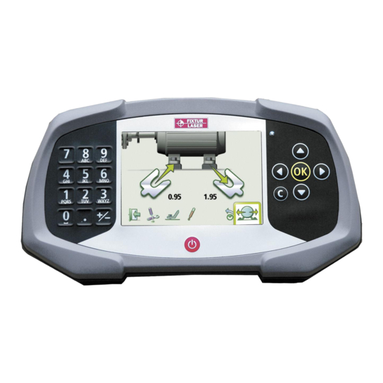
- Page 35 The arrows show if shims must be added or removed to adjust the machine in the vertical direction. The check signs show that shimming is not needed. Fixturlaser GO Pro Manual 2 edition 6.19...
- Page 36 Adjust the machine vertically until the values for both angular and parallel alignment are within tolerance. The arrows at the feet show in which direction the machine shall be moved. Fixturlaser GO Pro Manual 2 edition 6.20...
- Page 37 Adjust the machine horizontally until the values for both angular and parallel alignment are within tolerance. The arrows at the feet show in which direction the machine shall be moved. Fixturlaser GO Pro Manual 2 edition 6.21...
- Page 38 12 or 3 o‟clock When the coupling backlash or positions (within looseness is eliminated to avoid any of +/-3°). the above conditions, the looseness Flashing red: Measurement in indicator will automatically disappear. progress. Fixturlaser GO Pro Manual 2 edition 6.22...
- Page 39 The screen can be flipped to get the in the measurement, this is indicated with the Target motor at the left side. Value symbol in the upper Select screen flip in settings. right corner of the screen. Fixturlaser GO Pro Manual 2 edition 6.23...
- Page 40 Register the first reading at 9 o'clock, rotate the shafts 180° and register the second reading at 3 o'clock, rotate 90° back to 12 o'clock to register the third and final reading. Fixturlaser GO Pro Manual 2 edition 6.24...
- Page 41 The Fixturlaser system has two further documentation purposes. measuring units that are placed on each shaft by using the fixtures supplied with the system. After rotating the shafts to different measuring positions, the system calculates the relative position Fixturlaser GO Pro Manual 2 edition...
- Page 42 Check coupling assembly and Are there any restrictions for loosen the coupling bolts. mounting the measuring system? Check soft foot conditions. Is it possible to rotate the shafts? Mechanical looseness. What shim size is needed? Fixturlaser GO Pro Manual 2 edition...
-
Page 43: Machines
“Shaft Alignment Horizontal Machines”. Check coupling gap (axial alignment). STARTING THE PROGRAM Start the program by selecting the Vertical Shaft Alignment icon in the Main Menu and press OK. Go to Settings for selecting settings. Fixturlaser GO Pro Manual 2 edition... - Page 44 Settings unique for this application: Sampling time Select normal or long sampling time. To change sampling time, select the sampling time icon and press OK. Select normal or long sampling time with the left/right buttons and press OK. Fixturlaser GO Pro Manual 2 edition...
- Page 45 1, or filter type 2 with the left/right buttons and press OK. Note: For normal operation, the adjustable screen filter should be deactivated, and only activated in environments with severe vibrations. Exit Exits the Settings and returns to the application. Fixturlaser GO Pro Manual 2 edition...
- Page 46 In the Vertical Shaft Alignment program, machinery positions are The screen displays the movable calculated by taking three points with machine. 180° of rotation. Select the dimension boxes to enter dimensions. Measure and enter dimensions. Fixturlaser GO Pro Manual 2 edition...
- Page 47 Select the register icon and easiest to turn the shafts through 180°. press OK. Tip: Mark the positions 1, 2 and 3 This registers the first before you start measuring. reading. Fixturlaser GO Pro Manual 2 edition...
- Page 48 Rotate the shafts 90° to the third position (where you are standing). position, to the left. Select the register icon and Select the register icon and press OK. press OK. This registers the second This registers the third reading. reading. Fixturlaser GO Pro Manual 2 edition...
- Page 49 The symbol to the left of the coupling Go to alignment. values indicates the angular direction and offset, and also if the values are within tolerance. Fixturlaser GO Pro Manual 2 edition...
- Page 50 The foot values indicate the movable machine‟s foot positions where corrections can be made. Fixturlaser GO Pro Manual 2 edition 7.10...
- Page 51 The angular error is Re-measure. displayed live in the first direction when the sensors are placed in position number 1, and in the second direction when they are placed in position number 2. Fixturlaser GO Pro Manual 2 edition 7.11...
- Page 52 Fixturlaser GO Pro Manual 2 edition 7.12...
-
Page 53: Machine Defined Data
M- sensor and the first pair of feet and the distance between the first and the second pairs of feet, Target Values as feet values or angle and offset values. Tolerances. Fixturlaser GO Pro Manual 2 edition... - Page 54 Scroll downwards. and press OK. USING MACHINE DEFINED DATA Continue to Shaft Alignment Continue to Shaft Alignment with machine defined data for the selected machine. A list of machine types with preloaded data is shown. Fixturlaser GO Pro Manual 2 edition...
-
Page 55: Softcheck
All the distances must be entered, STARTING THE PROGRAM before checking for soft foot. Start the Softcheck by selecting its icon in the Shaft Check that all foot bolts are firmly Alignment program and press tightened. Fixturlaser GO Pro Manual 2 edition... - Page 56 MEASUREMENT VALUE REGISTRATION Loosen the bolt fully and then tighten it Select a bolt of your firmly, preferably with a dynamometric choice and press OK. wrench. Press OK to register the measurement value. Fixturlaser GO Pro Manual 2 edition...
- Page 57 (the values show approximately how many shims Re-measurements can be done at any that are needed to eliminate the soft time by selecting the requested bolt foot). again and press OK. Fixturlaser GO Pro Manual 2 edition...
- Page 58 SHAFT ALIGNMENT Return to shaft alignment by selecting the Exit icon and press OK. Fixturlaser GO Pro Manual 2 edition...
-
Page 59: Target Values
TARGET VALUES INTRODUCTION In the Fixturlaser GO Pro system, you Most machines develop a certain can enter target values while doing your amount of heat while running. In the alignment work. Accepted values are best case both the driving and the feet values and angle and offset values. - Page 60 Select one of two ways to express the distances. offset values: Feet values or angle and offset values. Fixturlaser GO Pro Manual 2 edition 10.2...
- Page 61 0.05 mm towards you and the front feet obtain perfect alignment during running will move 0.03 mm away from you while condition. the movable machine does not change its position while running. Fixturlaser GO Pro Manual 2 edition 10.3...
- Page 62 +0.02 mm/100 mm angular or mils/inch and mils, according to the misalignment and a +0.03 mm offset, in pre-set measurement unit. cold condition to obtain perfect alignment while running. Fixturlaser GO Pro Manual 2 edition 10.4...
- Page 63 SHAFT ALIGNMENT Return to shaft alignment by selecting the Exit icon and press OK. Fixturlaser GO Pro Manual 2 edition 10.5...
- Page 64 Fixturlaser GO Pro Manual 2 edition 10.6...
-
Page 65: Memory Manager
Goes to archive (only available when it contains folders with older files). Delete Deletes selected file. Select file Files can be selected by scrolling. Exit Scroll upwards. Exits the Memory Manager. Scroll downwards. Fixturlaser GO Pro Manual 2 edition 11.1... - Page 66 These folders can then be found in the archive. NOTE: When there are a lot of files in the memory, processing can be slow. Fixturlaser GO Pro Manual 2 edition 11.2...
- Page 67 When saving a measurement, both a text file and a picture file (bmp) are created. Enter file name Enter file name with the keyboard, when the file name field is selected. Confirm Confirm. Fixturlaser GO Pro Manual 2 edition 11.3...
- Page 68 PC in order for the display unit to appear on the PC. The files in the display unit can be transferred to the PC using the ordinary functions in Windows Explorer (i.e. cut, copy or drag and drop). Fixturlaser GO Pro Manual 2 edition 11.4...
- Page 69 Deletes the measurement file. The screen displays measurement results, dimensions, target values if any, file name, date and time, serial number of the display unit, program, program version, calibration date and tolerances. Fixturlaser GO Pro Manual 2 edition 11.5...
- Page 70 Deletes the measurement file. The screen displays measurement results, dimensions, file name, date and time, serial number of the display unit, program, program version, calibration date and tolerances. Fixturlaser GO Pro Manual 2 edition 11.6...
-
Page 71: Global Settings
To change time, select the time icon selection is shown in the icon. and press OK. Enter hour and press OK. The program version number is also Enter minute and press OK. shown on this screen. Fixturlaser GO Pro Manual 2 edition 12.1... - Page 72 Battery type Changes between standard batteries and rechargeable batteries To change battery type, select the battery type icon and press OK. Select standard batteries or rechargeable batteries with the left/right buttons and press OK. Fixturlaser GO Pro Manual 2 edition 12.2...
-
Page 73: Display Unit Go Pro D
DISPLAY UNIT GO PRO D Alfa-numeric keyboard LED indicator On/Off button Navigation buttons Fixturlaser GO Pro Manual 2 edition 13.1... - Page 74 Off icon in the main menu and press OK or while in the main menu press the On/Off button on the front. USB slave In case the system fails to respond, remove the batteries and reinstall them. Fixturlaser GO Pro Manual 2 edition 13.2...
- Page 75 POWER SUPPLY CONNECTIONS Fixturlaser GO Pro is powered by three 1.5V LR-14 (C) Alkaline batteries or by USB slave; for attaching the DU 1.2V NiMH HR-14 Rechargeable Nickel to a PC. Metal Hydride cells. Only use high performance alkaline WARNING! batteries.
- Page 76 (i.e. resuming operation without loss of data) or start the main menu. Fixturlaser GO Pro Manual 2 edition 13.4...
- Page 77 PC in order for the display Settings and stored measurements will unit to appear on the PC. not be affected by an upgrade. Copy the file containing the new software to the display unit. Fixturlaser GO Pro Manual 2 edition 13.5...
- Page 78 The upgrade file will be automatically deleted from the display unit when the upgrade is completed. Fixturlaser GO Pro Manual 2 edition 13.6...
-
Page 79: Wireless Transceivers
The wireless transceivers/battery packs Battery status indicator. uses standard Bluetooth technology. Flashing red – low battery. Status indicator. Continuously green – ON and connected. Flashing green – ON and trying to connect. On/Off button. Battery compartment. Fixturlaser GO Pro Manual 2 edition 14.1... - Page 80 5 seconds after Before using the wireless which it will automatically try to option make sure that there reconnect. are no restrictions on radio transceivers on the site. Do not use on aircraft. Fixturlaser GO Pro Manual 2 edition 14.2...
- Page 81 When connected to Fixturlaser M1 or S1 the operating time will be over 8 hours continuously measuring. The battery warning LED will flash when the batteries need to be replaced.
- Page 82 You have to exit the settings menu in order for the changes to take place. Information on which units are paired to the display unit is displayed. The display unit will only communicate with units that are paired. Fixturlaser GO Pro Manual 2 edition 14.4...
- Page 83 Fixturlaser. touch the search icon to search for units that are available. If there already are units paired to the display unit press the delete icon to release them. Fixturlaser GO Pro Manual 2 edition 14.5...
- Page 84 Choose the unit to pair with Select the OK icon and press the display unit from the list. OK to confirm wireless That unit will be automatically settings. paired and stored by the display unit. Fixturlaser GO Pro Manual 2 edition 14.6...
- Page 85 If still not connected, try at together without any obstructing another location or contact your objects between them – wait one nearest Fixturlaser represent- minute. ative. Fixturlaser GO Pro Manual 2 edition 14.7...
- Page 86 Fixturlaser GO Pro Manual 2 edition 14.8...
-
Page 87: Technical Specification
TECHNICAL SPECIFICATION – FIXTURLASER GO PRO D GO Pro D Part. No. 1-0876 Housing material High impact ABS plastic and TPE rubber Operating temperature -10 to 60°C ( 14 to 140°F) Storage temperature -20 to 70°C ( -4 to 158°F) Relative humidity 10 –... - Page 88 Class I Bluetooth transceiver with multi- drop capability Power supply 3 x 1.5V LR-14 (C) Alkaline batteries or 1.2V NiMH HR-14 Rechargeable Nickel Metal Hydride cells. Operating time 30 hours typical use LED indicator Green/Red Fixturlaser GO Pro Manual 2 edition 15.2...
- Page 89 Environmental protection IP 65 Laser 650 nm class II diode laser Laser line fan angle 6° Laser line width (1/e 1.6 mm Laser line divergence (full angle) 0.25 mrad Laser power < 1 mW Fixturlaser GO Pro Manual 2 edition 16.1...
- Page 90 Detector resolution 1 µm Measurement accuracy 0.3% ± 7 µm Ambient light protection Optical filtering and ambient light signal rejection Inclinometer resolution 0.1° Inclinometer accuracy ±0.5° LED indicators Laser transmission and status indicators Fixturlaser GO Pro Manual 2 edition 16.2...
- Page 92 All rights reserved. No part of this manual may be copied or reproduced in any form or by any means without prior permission from Elos Fixturlaser AB. The content in this manual may be changed without prior notice. Reports on any misspelling or other errors in this manual are appreciated.
Need help?
Do you have a question about the GO Pro and is the answer not in the manual?
Questions and answers