Table of Contents
Advertisement
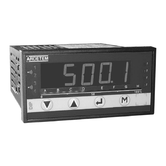
DIGITAL PANEL METERS
programmable ±10 000 points
ÉTUDES ET RÉALISATIONS
DIP 400
ÉLECTRONIQUES / INSTRUMENTATIONS / AUTOMATISME
Route de Brindas - Parc d'activité d'Arbora - N°2
DIP 401
69510 - Soucieu en Jarrest
Tél. 04 72 31 31 30 - Fax 04 72 31 31 31
DIP 402
Tel. Intern. 33 4 72 31 31 30 - Fax Intern. 33 4 72 31 31 31
User handbook
Valid for the instruments with version 08.xx
http: //www.ardetem.com - e-mail: info@ardetem.com
ARDETEM
Soucieu en Jarrest - FRANCE
Advertisement
Table of Contents

Summary of Contents for ARDETEM DIP 400
- Page 1 Tél. 04 72 31 31 30 - Fax 04 72 31 31 31 DIP 402 Tel. Intern. 33 4 72 31 31 30 - Fax Intern. 33 4 72 31 31 31 User handbook Valid for the instruments with version 08.xx http: //www.ardetem.com - e-mail: info@ardetem.com ARDETEM Soucieu en Jarrest - FRANCE...
-
Page 2: Table Of Contents
Summary Summary 1 . INTRODUCTION 4.9 Programming of a new access code 4.10 accessible functions from the main menu 2 . SPACE REQUIREMENTS 4.10.1 - Display simulation 4.10.2 - Simulation of the analog output 3 . CONNECTINGS 4.10.3 - Menu CLEAr: Deleting of the recorded alarms 4 . -
Page 3: Introduction
The series DIP 40- offers a complete range of highly accurate program- (See the features of the DIP 400 and DIP 401 on the left hand column) mable digital panel meters. Each instrument is equipped on front face Resistive sensors: calibers 0-400 Ω... -
Page 4: Space Requirements
2. SPACE REQUIREMENTS Dimensions of the case: (with terminals) 96 x 48 x 124 mm Holding panel max. thickness 30 Terminals case external tightenings seal Panel mounting cut out 44 x 91 mm Protection: Front face: IP 65 Housing: IP20 Terminals: IP 20 Housing: Self-extinguishing case of... -
Page 5: Power Supply
3. CONNECTIONS INPUTS DIP 402 DIP 400 PROCESS TEMPERATURE DIP 401 RESISTANCE and POTENTIOMETER Location of the terminals (view from case rear face) Resistance from 0 to 440Ω 300V POWER SUPPLY Resistance >440Ω up to 2kΩ Pt100 3 wire (0-8kΩ optional) -
Page 6: Programming P5
4.2 Orientation through the programming 4. PROGRAMMING The dialogue is ensured by 4 keys located on the front face. 4.1 Communication with the instrument Several functions can be accessed directly on front face during the measure display: Exit from a submenu to access the next menu / access to the Functions Alarms... -
Page 8: B / Temperature Signals P7
b. Temperature signals c. Resistive sensors... -
Page 9: Programming Of The Display
4.4.2 Programming of the display Option analog output -88.88... - Page 10 Communication parameters...
-
Page 13: Resistance And Potentiometer Input P12
4.5.5 Logic inputs (option TOR) Measurable limit of the input Accuracy in • Board of 2 logic inputs: Input signal 24 Vdc Thermocouple % of the MR* °F °C Possible functions: -160 / 1200°C -256 / 2192°F 0.1 % tc-j Display hold in case of activation of the logic function. -
Page 14: Digital Output
Choice of the operating mode: ModE.x 4.6.2 Digital output: - RS485 (2 wire) digital data link • Mode setpoint - Protocoles format of the data: integer and double integer MODBUS JBUS - Transmission format: 1 start bit Caption: 8 bits without parity or 9 bits with parity coil supplied 1 stop bit OFF coil not supplied... -
Page 15: Safeties
· On the relays: tiME.x • Time delay on the alarm No influence on the relay in case of self-diagnosis error The relay time delay is adjustable from 000.0 to 025.0s., in 0.1s increases. It is active both on switching and switching back. Relay de-activated (coil supplied) in case of self-diagnosis error •... -
Page 16: Display Features
4.6.5 Display features: For a 4/20 mA signal from a level sensor on a tank, the following programming is displayed: The parameters down and full display scale, cut-off and ordinates (if input lin- POINT FUNCT = LinEA = _ _ _ . _ d.in = 4.00 earised in segments) are to be considered in the magnitude of the programmed physical scale. - Page 17 br.bAr LEd7 • Setting of the bargraph and the leds brightness Programming of led 7 Lowest brightness Strongest brightness 1 1 1 1 4444 Led still (no associated function) The brightness level can be visualised directly on the leds 5 to 8 and on The led 7 will be lit during the instrument response the bargraph.
- Page 18 Special linearisation Li.SPE For specific applications such as the measurement of volumes, the meter can memorise an unlinear curve, programmable in X and in Y. The curve resulting from your equation can be replaced by a series of linear segments, with a maximum of 20 points (19 segments).
-
Page 19: Reading Of The Configuration
Submenu 4.7 Reading of the configuration rEAd About Validation / vertical move rEAd Validation / vertical type of the instrument move Reading of the input parameters XXXXX InPut 12345 Reading of the measure display parameters number of the instrument diSPL. X1 : - : no analog output Reading of the analog output parameters AnA. -
Page 20: Programming Of A New Access Code
4.9 Programming of a new access code 4.10.2 Simulation of the analog output (mode generator) (accessible according to the programmed Enter previ- access code and if option analog output) if code not valid P .CodE ous code (old) if code correct This function allows GEnE (old) -
Page 21: Functions Which Can Be Accessed Directly From The Measure Display
only for process, resistance and 5. FUNCTIONS WHICH CAN BE ACCESSED potentiometer inputs DIRECTLY FROM THE MEASURE DISPLAY 4.10.4 Menu : Suppressing of the programmed tare CLr.tA (accessible according to the programmed access code) 5.1 Functions which require pressing only 1 key : the memorised tare will not a / Display of the min. -
Page 22: Functions Which Require Pressing Several Keys
5.2 Functions which require pressing several keys: note: only for temperature inputs: From the menu rEAd, the performed scale shiftings can be visualised in the submenu InPut: 5.2.1 Display shifting (accessible acc. to the programmed access code) offset slope and OFFSE. -
Page 23: Visualisation And Setting Of The Alarm Setpoints P22
6. ERROR MESSAGES 5.2.3 Visualisation and setting of the alarm setpoints Option 2 or 4 relays Measure in overrange Upper or lower electrical 2000 ---- overstepping of the input Setting of the setpoints: There are 2 ways to adjust setpoints: Sensor rupture OPEn - either in mode programming entering the correct safety access code... - Page 24 Inputs InPut Access to the submenu programming of the input Delta PT100 input Type of the input NI100 input tYPE ni 100 Voltage input Type of degrees Current input Celsius degree Temperature input Farentheit degree tEMP Potentiometer input Input shifting AdJuS.
- Page 25 Display Last digit (bottom weight) L.dIG diSPL. Access to the submenu programming of the display Last digit in service Last digit enforced to 0 Choice of the decimal point location Point Deleting of the unsignificant zeros nuLL Place of the decimal point --.-- d.in Input down scale...
- Page 26 Digital output t.Actx Positionning of the time delay Access to the RS output programming submenu JbuS SIMPL. Time delay on switching on alarm Time delay on switching on alarm and off alarm Slave number SLAvE doubL Transmission speed (baud rate) bAud Programming of the relay associated led LEdx...
-
Page 27: Annexe: Modbus
out.U out.I Return value (or not) of the output in case of 9. ANNEXE: MODBUS self-diagnosis error Return value required No return value rEPLi Return value 9.1 Table of the modbus addresses Saving of the configuration Saving of the configuration Word address Description SAvE... -
Page 28: Correspondance With The Dip400/Dip402 Version
Table of the units 9.2 Correspondance with the DIP400/DIP402 version 7.0 Code Unit Code Unit Code Unit Code Unit Code Unit 023 MVARh 100 °C 122 mm/s 144 mV DC 024 GVARh 101 °F 001 V 123 cm/s 145 V DC Address Format nbr of words... -
Page 29: Description Of The Born Modbus Functions
Writing of 1 word: Function N°6: • Displayed measure: Request sequence: The value of the displayed measure is taken up without the decimal point. To read the value of the decimal point, read the word at the address 120. Value of Slave Function Adress of... -
Page 30: Crc 16 Calculation Algorythm
Measure = byte 3 x 256 3 + byte 4 x 256 2 + byte 1 x 256 + byte 2 9.5 CRC 16 calculation algorythm: = 0 x 256 3 + 0 x 256 2 + 19 x 256 + 136 FFFF →...
Need help?
Do you have a question about the DIP 400 and is the answer not in the manual?
Questions and answers