
Summary of Contents for EZER Horus+ Scope
-
Page 1: User Manual
Horus + Scope Digital Eye Fundus Camera User Manual DOC. No. 2014.01-A Copyright@2014 MiiS Inc. All right reserved. -
Page 2: Table Of Contents
Contents Preparations • Before use • Names of components • Charging the battery • Power indicator • Assembling • Using the Setup mode • Entering the patient ID Taking pictures • Sequence of operations • Photo mode • Video mode • Fixation setting and holding position • Q&A troubleshooting Playback • Display mode • Enlarged viewing • Deleting pictures Miscellaneous • Files transferring • Viewing on a computer/laptop screen •... -
Page 3: Before Use
Preparations Before use Prior to installation and start-up of the digital eye fundus camera, carefully read the user manual. As with all technical devices, the proper function and safety operation of this device depend on the user complying with the safety recommendations presented in these operating instructions. -
Page 4: Names Of Components
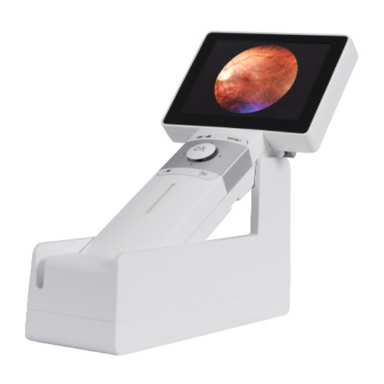
Intended for use Also refer to “Usage cautions and notes” Horus+ Scope EZ-Horus 45 is a digital hand-held eye fundus camera used to record digital photographs and video of fundus (including retina, macula, and optic disc) of the human Please also refer to “Usage cautions and notes”... - Page 5 Brightness decrease/increase in photo mode (0B ~ 15B) ‹‹ SD slot Power indicator Optical Lens of Horus+ Scope EZ-Horus 45 (Digital Eye Fundus Camera) Bottom view ›› Contact Lens assembling mark surface AV out / foot switch...
-
Page 6: Charging The Battery
Charging the battery Open the battery cover by digging out the gap in the bottom of battery cover with a finger or something pointed. • Tilt the battery cover and remove the battery cover by lifting it up. • Remove the original battery and replace a new battery along the correct direction. Always charge before first use •... -
Page 7: Assembling
Assembling Using the Setup mode Step 1. ↘ Turn on the power Align the marks of the optical lens and control unit. To turn on the system, press the power button (→ 7) to turn on the control unit. Approxi- mately one to two seconds later, the boot screen will appear on the LCD panel. - Page 8 Exit the [Setup] menu [Picture Color Temperature] The picture color temperature has three levels; the default setting is medium. Once a setting adjustment is made, the new value affects the system immediately. Use the upper back button or the OK button to exit the screen. Settings [Aiming Light/Capture Light] The default setting of [Aiming Light/Capture Light] is [IR/White LED].
- Page 9 UVC mode. A freeware webcam application (e.g., AMCap) is a software that can re- [Format SD Card] ceive UVC signal on the computer. User can search for relevant information over the User can format the SD card. Internet. [Standby] User can set standby mode to be on or off. Once the mode is on, the LCD panel will be turned off if the system is idle for three minutes.
-
Page 10: Entering The Patient Id
Entering the patient ID Using patient ID as partial file name is supported in EZ-Horus 45. File naming rule Model Name Picture Name without ID Picture Name with ID ELHHMMSS.jpg ELXXXXXXXXXXHHMMSS.jpg EZ-Horus 45 fundus ERHHMMSS.jpg ERXXXXXXXXXXHHMMSS.jpg camera Meaning of each symbol: Symbol Meaning Left eye photo taken by the eye fundus camera... -
Page 11: Taking Pictures
Taking pictures Sequence of operations Step 1: Turn on the power Press the power button to turn on the control unit. Approximately one to two seconds later, the boot screen will appear on the LCD panel. After about 10 seconds, the information icons will appear on the top of the LCD panel. -
Page 12: Photo Mode
Photo mode Video mode The device’s default setting is “photo mode.” The user can take a picture or video in “photo Video mode: Completely press the OK button to start recording. Press again to end record- mode” or “video mode,” respectively. ing. -
Page 13: Fixation Setting And Holding Position
Fixation setting and holding position Examination conditions After the optical lens is attached to the control unit and setup is complete, the user can start taking images. Approaches for taking the image of human eye fundus are as follows: • Have the examinee stay in <5 lux dark room; in such an environment, a newspaper is nearly impossible to see. -
Page 14: Q&A Troubleshooting
Q&A troubleshooting Playback Display mode A good image should have two characteristics: Optic disc 1. Positions Macula The macula and the optic disc are horizontally aligned in the middle. Touch the photo icon and then the display icon to see the photos that have been taken. 2. -
Page 15: Deleting Pictures
Miscellaneous After the image is enlarged (1:1), the arrows would work as pan functions. Tap Zoom icon again to return the original scale. Move the enlarged section upward Files transferring Transfer images to an electronic device (e.g., personal computer, laptop, or mobile phone) via the USB cable or SD card. - Page 16 Charging the battery EMC (electromagnetic compatibility) • The time required for charging varies depending on the conditions of battery usage. Charg- During installation and operation of the device, observe the following instructions: ing takes longer at high or low temperatures and when the battery has not been used for •...
-
Page 17: Technical Description
Technical description NOTE It is recommended to remove the battery if the device is stored over two weeks. Horus+ Scope EZ-Horus 45, digital eye fundus camera: Environment for Transportation • Ambient temperature: -40°C to +70°C • View Angle: 45 Degree (Typical) •... -
Page 18: Liability
Liability Standards Electrical safety IEC 60601-1:2005 (EN 60601-1:2006) Manufacturer considers itself responsible for the effects on safety, reliability, and performance EMC and regulatory compliance IEC 60601-1-2:2007 of the device only if (EN 60601-1-2:2007) • Assembly operations, extensions, readjustments, modifications or repairs are carried Ophthalmic instruments-Fundamental requirements and out by persons authorized. - Page 19 Guidance and manufacturer’s declaration electromagnetic immunity Field strengths from fixed RF transmitters, as deter- mined by an electromagnetic site survey, should be less The device is intended for use in the electromagnetic environment specified below. The cus- than the compliance level in each frequency range. tomer or the user of the device should assure that it is used in such an environment.
Need help?
Do you have a question about the Horus+ Scope and is the answer not in the manual?
Questions and answers