
Summary of Contents for Merit RC MR-600
- Page 1 MT-600&MR-600 2.4GHz 2.4GHz Radio Radio System ystem Instruction Instruction Manual anual...
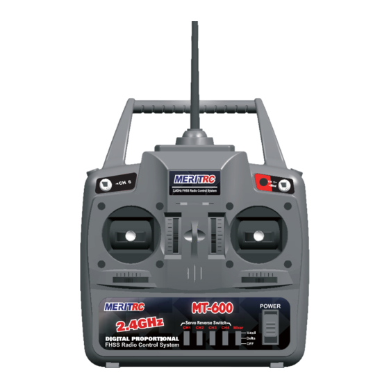
- Page 2 Used to electronically change the on-board Mixer options.Choose from OFF, Delta,and V-tail.
- Page 3 Charging jack Battery cover Use when replacing the battery . Slide the cover downward while pressing the part marked " ". MR-600 RECEIVER Channel Output "1": Aileron servo (CH1) "2": Elevator servo (CH2) Pair button "3": Throttle servo (CH3) (At s id e of b ox) "4": Rudder servo (CH4)
- Page 4 flight with the 2.4GHz system. Receiver ’s Antenna installation The MR-600 has two antennas. These antennas have a diversity function to decrease the chance of a receiving error. The wavelength of the 2.4GHz is much shorter than that of the conventional frequencies, it is very susceptible to loss of signal which results in a receiving error.
- Page 5 Transmitter antenna 1. The transmitter antenna is adjustable so please make sure that the antenna is never pointed directly at the model when flying as this creates a weak signal for the receiver. 2. Keep the antenna perpendicular to the transmitter's face to create a better RF condition for the receiver.
- Page 6 Binding Setup Programming a receiver to recognize the code of only one specitic transmitter. If you change transmitters or add a receiver, you must re-bind before operating your vehicle. 1. Place the transmitter and the receiver close to each other (within one meter). Turn the power switch on the transmitter to the ON position.
- Page 7 Change the transmitter ID The transmitter has a individual randomize ID that is created in the factory, Even it is almost have no chance to meet the same ID transmitter in the same fly field, in case it does happen. T he transmitter has an ID set up function.
-
Page 8: Transmitter Operation And Movement Of Each Servo
Transmitter Operation and Movement of Each Servo Before making any adjustments, learn the operation of the transmitter and the movement of each servo. (In the following descriptions, the transmitter is assumed to be in the standby state.) AILERON OPERA TION When the aileron stick is moved to the Aileron(ch1) (Viewed from the rear) -
Page 9: Connection Example
Connection example is shown below. Connection Example *The number of servos depends on the set. Aileron (CH1) Elevator Receiver (CH2) MR-600 Thr ottle (CH3) Rudder (CH4) Receiver switch *Insert four batteries. *When using 5 or more servos, use the nicd battery sold separately. -
Page 10: Antenna Installation
WARNING Connector Connection Servo Thr ow Insert the receiver, servo, and Operate each servo horn over battery connectors fully and its full stroke and adjust so that firmly. the pushrod does not bind or is not too loose. If vibration, etc. causes a connector to work loose during flight, the plane may Unreasonable force applied to the servo crash. - Page 11 Adjustments The operating dir ection, neutral position, and steering angle of each servo ar e adjusted. CAUTION The basic linkage and adjustments of the fuselage conform to the fuse- lage design drawings and kit instruction manual. Be sure that the center of gravity is at the prescribed position.
Need help?
Do you have a question about the MR-600 and is the answer not in the manual?
Questions and answers