Table of Contents
Advertisement
Quick Links
Advertisement
Table of Contents

Subscribe to Our Youtube Channel
Summary of Contents for Technalogix tp400d-8vsb
-
Page 1: User Manual
TP400D-8VSB TRANSMODULATOR / PROCESSOR User Manual Version 1.5... - Page 2 It is highly suggested users to go through this document before actually operating the device. If you need help, please contact us at: Technalogix Ltd. #4, 8021 Edgar Industrial Place Red Deer, Alberta, Canada T4P 3R3 Phone: 403.347.5400...
-
Page 3: Table Of Contents
Contents About this product…………………………………………………………………...…………..4 1.1 Introduction……………………………………………………………………..…….……..4 1.2 Safety…………………………………………………………………………………………….….4 1.3 Architecture…………………………………………………………………………………..……5 1.4 Methods of Operations…………………………………………………………………….…..6 Operations through WEB GUI…………………………………………………..……6 1.4.1 Operations through Front Panel………………………………….…..………..…..7 1.4.2 1.5 Technical Specifications………………….…………………………………………….……..7 1.5.1 Physical Specifications…….……………………………………………..………………….…..….7 1.5.2 Performance and Capacity………………….……………………………........7 1.5.3 Interfaces and Protocols…………………………………………………........8 Installation………………………………………………………………………………………….…...9 2.1 Installation Procedures………………………………………………………………………………...9 2.2 Preparation before Installation…………………………………………………………………...…...9 2.3 Check Package and Accessories……………………...……………………………………….…...10 2.4 Equipment Wiring and Connections………………...…………………………………………..10... -
Page 4: About This Product
About This Product 1.1 INTRODUCTION This product is a new generation Transmodulator/Processor to support the growing demands for multi-format, multi-standard video delivery and distribution. It can receive digital signals from several inputs i.e. 8-VSB, (DVB-S/S2, DVB-C (optional), DVB-T/T2/ISDB-T (optional), ASI, and others), It can also decrypt and process/select programs to various outputs including CVBS, HDMI, SD/HD SDI, ASI, Output Modulator, etc. -
Page 5: Architecture
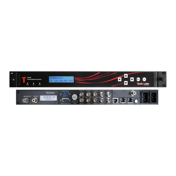
1.3 ARCHITECTURE The equipment of this section is shown in the schematic diagram. It is subject to change due to improvements or advancements in the product. Changes may be made without advanced notice. Front Panel PIC-1.3-1 1. Power status indicator: This LED light is turned on when the unit is power on. 2. -
Page 6: Methods Of Operations
PIC-1.3-2 RF LOOP IN RF OUT GPI/LS DATA Out CVBS Out R-AUDIO 1 R-AUDIO 2 ASI OUT 2 ASI IN 2 RF IN BALANCED AUDIO OUT HDMI SDI OUT L-AUDIO 1 L-AUDIO 2 ASI OUT 1 ASI IN 1 MANAGEMENT TS/IP TS/IP (Redundant) POWER CORD IN... -
Page 7: Operations Through Front Panel
1.4.2 Operation through Front Panel Operation Operation through front panel control buttons; users may configure all the parameters according to the following: Functions Description Related Items Allows users to conduct operations of Signal receive setup Parameters parameters CI setup Setting configuration, Decoder setup modification and... -
Page 8: Interfaces And Protocols
1.5.3 Interfaces and Protocols IP input ASI input Interface: 2 ASI inputs, 75Ω Interface: 1 x 1000 Mbps MPEG Format: 188/204 Bytes per IP Encapsulation: UDP/RTP MPEG TS: MPTS and SPTS Max bit rate: 100 Mbps Input processing: Up to 2 channels, max at 72 Mbps per Support input redundancy. -
Page 9: Installation
Installation 2.1 INSTALLATION PROCEDURE Preparation before Installation Check Package and Accessories Setup Connection (signals, wiring) Parameters Configuration System Debug Finish 2.2 PREPARATION BEFORE INSTALLATION Before installation, the installation personnel should read through and confirm the following: Thoroughly read this user manual. ... -
Page 10: Check Package And Accessories
2.3 CHECK PACKAGE AND ACCESSORIES The unit packaging includes the following accessories: Base Unit x1 Power cord x2 Ground Wire x1 BNC cord x1 BNC-RCA cord x2 User Guide Disc x1 2.4 EQUIPMENT WIRING AND CONNECTION To avoid electric shock and damage to the equipment, before setting up the wiring connection, please power off the equipment and all other connected external devices. -
Page 11: Connection Setup For Rf Signal Input
In actual application, not all connection interfaces need to be connected with signal/external devices. Please connect according to actual application purpose. To ensure a smooth communication between the management PC and the TP400D, please try to connect the UNIT management port to a switch without large data processing. -
Page 12: Operation Guide
Operation Guide 3.1. OPERATION OVERVIEW This chapter provides information on how to operate the TP400D through front panel and WEB GUI. User can select the appropriate operation method to set up the unit. 3.2. POWERING UP AND INITIALIZATION Switch on the equipment through the rear power switch, and the unit is powered up and starts the initialization process. -
Page 13: Front Panel Menu Structure
3.3.1 Front Panel Menu Structure Front Panel Menu Structure Layer Layer Layer Lock Status Frequency Offset Input Tuner 1/2 Frequency Tune TS Rate RF Level Lock Status Input ASI 1/2 TS Rate Lock Status Status Input IP 1/2 TS Rate TS Rate PCR PID Audio PID... - Page 14 LNB Power Supply LNB 22KHz Scan TS Enable ASI 1/2 TS Standard Scan TS Local Setting TSIP Channel 1/2 TS Source Playing Program Program List Video Standard Video Aspect Ratio Video Format Decoder Audio Volume Audio Audio Mixer Audio 1/2 Language Subtitle Subtitle Standard Outputs...
-
Page 15: Front Panel Operation Guide
BISS Mode BISS Setting BISS Setup BISS-1 Setup BISS-E Setup Local IP Address Local Network Mask Local Gateway System Local Setup MAC Address Version Factory Setting Reboot 3.3.2 Front Panel Operation Guide Enter “Menu”: o Press “MENU” button to enter main menu. ... -
Page 16: Web Gui Operation
3.4. WEB UI OPERATION (RECOMMENDED) Accessing the equipment via Web can be very convenient for remote configuration of the equipment. Relative to the front panel settings WEB operation can provide a friendlier man-machine interface, and with less limits in space. WEB Management is recommended. -
Page 17: Parameters Configurations
PIC-3.4-2 To login, you need to enter the default username “admin” and password “admin”. Then click “Submit”. If the user name and password is correct, it will redirect to the main page. 3.4.2 Parameters Configuration 3.4.2.1 Main Page Menu Area Parameters Area PIC-3.4-3... - Page 18 parameter setting and monitoring pages. Parameters Area: displays the corresponding parameters pages according to the menu selection. The WEB management page allows you to monitor and/or configure: Status, Receiver, Program Setup, CA, Local Setup, Alarms Setup, User Management, Preset, Upgrade, Log and etc.
-
Page 19: Status Page
3.4.2.2 Status Page This page allows you to monitor the status of input and output signal, and check the information of CI cards. PIC-3.4-5 Input status (tuner/ ASI/ IP): It shows the main information of input streams, such as lock status, RF BER, RF Level, Total RF Rate , ASI total rate, ASI effective rate etc. -
Page 20: Program Mux Settings
3.4.2.3 Programs Mux Setting s If you want to configure the parameters of multiplexed programs, just click the “programs Mux Setting” button on the left bar. Then you will turn to the programs information interface, where you are able to check and modify the parameters of programs. PIC-3.4-6 ①... - Page 21 How to dispose the Inputs: To get the input programs, you should choose the sub-menu in the Inputs menu on the left. Then it will turn to the corresponding page where you are able to set the receiving parameters to lock the signals. (Referring to chapter 3.4.2.4) If the signal is locked then programs information will be listed on the frame as the following picture shows.
- Page 22 PIC-3.4-9 Also, by clicking the edit icon, you are able to modify the TS name, network ID and TS To delete existing TS, you can click the minus icon as follows: PIC-3.4-10 And it is able to delete the TS or programs in the Mux menu by clicking the cross icon at the rear of the program or TS.
- Page 23 After completing the configuration, you should click “Apply” button to enter it or “Save” button to enter and save it. The outputs ( Mux1 and Mux2) will be available for ASI/ IP inputs after configuration.
-
Page 24: Inputs
3.4.2.4 Inputs DVB-S/S2 Area 1 Area 2 Area 3 PIC-3.4-12 Area 1/ Area 2 : In this section, you are able to set the dual RF receiver parameters including the Satellite Frequency, Symbol Rate, LNB Frequency, and LNB Voltage (Polarization) with accurate values. - Page 25 18V is for Horizontal while 13V is for Vertical. LNB 22 KHz: Generally this is used to control 22KHz switch, typically used for LNB with double L.O. in Ku band. “ON” is for high L.O and “OFF” is for low L.O. ...
- Page 26 Area 1 Area 2 PIC-3.4-13 This page shows the Input ASI information. There are two channels available to receive ASI streams: ASI1 and ASI2. Area1: set the ASI parameters, include Enable and TS Standard. Enable: enable / disable the ASI channel to receive input stream. TS Standard: select the correct TS standard: DVB or ATSC Area2: displays the programs list of the input stream.
- Page 27 Area1: Set the devices’ local IP parameters to enable it to be connected into the network: IP Address: Local IP setting for connecting to the server. This IP and the management server’s IP should be in the same section. ...
-
Page 28: Outputs
3.4.2.5 Outputs Decoder In this page, user can view and configure the decoding output program parameters, including: Program, CAM, Video, Audio, Subtitle and Teletext. PIC-3.4-16 The device can decode the input streams and output by CVBS or HDMI. For each time only one program can be decoded and output. The parameters set in “Program Setup”... - Page 29 Video: Here, you can configure the video parameter, as follows PIC-3.4-18 Video Standard: in this item, you can select video standard, available options include: Automatic, SECAM, NTSC, PAL-N, PAL-M and PAL. Aspect Ratio Conversion: you can setup the aspect ratio for the decoded programs, available options include: Pillarbox (Side Bars), 16:9 Pan and Scan, 4:3 LetterBox, and 4:3 Pan and Scan.
- Page 30 PIC-3.4-20 o Subtitle Standard: You can set the subtitle to be EBU or DVB. EBU: The European Broadcasting Union is the world's foremost alliance of public service media entities DVB: It means Digital Video Broadcasting, a set of standards relating to digital television o Subtitle Language: Here you can set the language of subtitle from the existing selections.
-
Page 31: Failover Slate
PIC-3.4-23 Enable: Enable or disable corresponding output channel TS Source: to choose the input signal as IP output. Dest IP Address: The IP address for the multicast/unicast. Dest Port: The port of the multicast/unicast, it must stay same with the value of the dest device. -
Page 32: Conditional Access
Sample of the Slate/Still image: PIC-3.4-25 3.4.2.6 Conditional Access (Optional, Consult Factory) In this page, user can manage the configuration setting related to the device decryption and descrambling capability. Area 1 Area 2 Area 3 PIC-3.4-26 Area1: this area is for CAM (Conditional Access Module) bit-rate setting, where you can set the maximum bit rate according to the CAM inserted. -
Page 33: System
Area2: This area is for the BISS setting. BISS (Basic Interoperable Scrambling System): is a satellite signal scrambling system developed by the European Broadcasting Union and a consortium of hardware manufacturers. There are two types: o BISS-1, transmission are protected by a 12 digit hexadecimal “session key”... - Page 34 In this page, you are able to configure the following parameters: IP Address: Local IP setting for connecting to the server. This IP and the management server’s IP should be in the same section. Network Mask: Network Mask setting for connecting to the server. It should be the same as management server: 255.255.255.0 ...
- Page 35 User Management PIC-3.4-29 Change Password: When the user puts a check on this button, user can change the password with a new one. Change Username: Here, you can change the existing username to a new one. Create a User: The device allows you to add up to 10 new users to operate the device.
-
Page 36: Preparation Before Official Operation
Upgrade PIC-3.4-31 Click Browse button, then user can select the upgrade file, and click “Upgrade” button to start the upgrade. If succeed, restart the device and it will load the new version Log In this page user can export and review the log of the machine. ... -
Page 37: Configure The Equipment With Working Data
3.5.3 Full check before implementation After completion of the test and configuration, users are recommended to give the equipment a final full-scale check to ensure everything is on track for working with long- term stability. It shall contain (but not limited to) the following items: ... -
Page 38: Faq
FAQ/Trouble Shooting Problem Possible Reasons What to do Check whether the power The LCD display on the front No power. cord is plugged into the panel does not light up. power socket. Parameters are not Check the parameters properly configured. configuration Check the source and No signal... - Page 39 Problem Possible Reasons What to do Signal is too weak. Change to a larger dish. LNB noise figure is too Change a LNB with lower high. noise figure. The LNB is defective Change a LNB. Insert correct CAM and Signal is good. But No picture The picture and audio are authorized smart card to and no audio on decoding output...
-
Page 40: Terminology
Terminology A - Z Abbreviation Specific Meaning Audio Engineering Society Asynchronous Serial Interface BISS Basic Interoperable Scrambling System Bayonet Nut Connector Common Interface CVBS Composite Video Broadcast Signal Digital Video Broadcast DVB-C DVB-Cable DVB-S/S2 DVB-Satellite DVB-T DVB-Terrestrial European Broadcasting Union ETSI European Telecommunications Standards Institute Forward Error Correction... -
Page 41: Specifications
SPECIFICATIONS AC Power Input, Single Power Supply Voltage 100-240 VAC, Dual Switching Supplies Current Max 60 Watts, <.2 Amps Typical Frequency 47-63 Hz Environmental Operating Temperature 0⁰ to 50⁰ C Maximum Altitude 10,000 Ft., 3048 Meters, AMSL Humidity 95%, Non-Condensing RF Input Frequency Range 57-803 MHz... - Page 42 Thank you for choosing Technalogix Ltd.
Need help?
Do you have a question about the tp400d-8vsb and is the answer not in the manual?
Questions and answers