
Summary of Contents for Micro Air Corporation FX-2
- Page 1 FX-2 Control Board ASY-360-XXX Setup and Configuration Guide Micro Air Corporation Phone (609) 259-2636 124 Route 526. WWW.Microair.net Allentown NJ 08501 (609) 259-6601...
-
Page 2: Table Of Contents
Table of Contents Introduction ......................... 4 Jumper settings........................ 5 Systems with EasyStart ....................... 6 Contactors ........................6 Capacitor Selection ......................6 Initial Starts ........................6 Forcing EasyStart to relearn.................... 6 Additional EasyStart Jumper Usage ................7 Normal ........................7 Re-learn ........................7 Default......................... - Page 3 Air Handler (AH) ...................... 29 Fresh Air Make Up Unit (FAMU) ................30 Display and Sensor Cable ..................... 30 CAN bus wire: ......................30 COPYRIGHT ........................31 © 2016 Micro Air Corporation, All Rights Reserved ........... 31 May 24, 2017 Revision 1.09...
-
Page 4: Introduction
FAMU is a software compatible option in compatible displays. It can function in both DX and AH systems. EasyStart is a factory installed option that must be ordered with the FX-2 power supply. It reduces compressor starting current by controlling start characteristics. -
Page 5: Jumper Settings
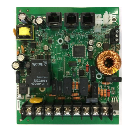
Jumper settings Hardware jumpers are provided on the FX-2 control board to provide additional functions. Printed circuit board (PCB) revision I and earlier have jumpers that must be set for proper display operation. Revision K and above automatically detect the display and do not have display setting jumpers. -
Page 6: Systems With Easystart
EasyStart may be reset to perform the learning process. This is used when changing compressors or if instructed by to manufacturer to do so. Follow these steps below to complete this process. Refer to the FX-2 DX EasyStart wiring diagram for jumper position identification. -
Page 7: Additional Easystart Jumper Usage
This setting disables the microprocessor on the board so no operation can occur. Use this setting on an FX-2 system if you are installing a compressor with its own start device and are not using EasyStart. In this case you must follow the wiring diagram for a standard FX-2 system. -
Page 8: Dc Fan Option Board
Do not connect the GND wire to an AC ground. The ‘S’ terminal is connected to the DC fans’ 0-10V signal wire. Connect the DC fan’s AC input directly to the AC line input. All other connections to the FX-2 control board are as they would be in a normal installation. Notes: ... -
Page 9: Can Bus Systems
CAN Bus Systems Basics The CAN system (Computer Area Network) is a communications protocol system that facilitates communication between electronic controls. Controls are connected to each other to form a network. Typical controls in a network could include ice makers, chilled and heated water systems, air handlers, and direct expansion systems. -
Page 10: Wiring Diagrams
Wiring Diagrams Board and Firmware revisions This manual makes reference to FX-2 control board printed circuit board (PCB) revisions. The PCB revision is found along the edge of the printed circuit board in white silk screened lettering and starts with PCB-360. PCB-360-00J indicates a revision J circuit board. -
Page 11: Using Contactors
Checking Contactors 1. Disconnect the contactor load from the contactor. 2. Disconnect the display by removing the plug from the display jack on the FX-2 control. 3. Apply power to the board from the AC mains power source. -
Page 12: Using Solid State Relays (Ssr)
Using Solid State Relays (SSR) Circuitry on the board may adversely affect the operation of an SSR by holding an SSR on when it should be off. Customers with applications using an SSR should contact Microair prior to purchase for factory modification of the board. Boards may also be returned to Microair for modification. -
Page 13: Rev I And Earlier
Rev I and Earlier Air Handler (AH): Rev I and Earlier PCB May 24, 2017 Revision 1.09... -
Page 14: Direct Expansion (Dx) Wiring: Rev I And Earlier Pcb
Direct Expansion (DX) Wiring: Rev I and Earlier PCB May 24, 2017 Revision 1.09... -
Page 15: Fresh Air Makeup Unit Wiring (Famu) Rev I And Earlier Pcb
Fresh Air Makeup Unit Wiring (FAMU) Rev I and earlier PCB May 24, 2017 Revision 1.09... -
Page 16: Easystart Wiring: Rev I And Earlier
EasyStart Wiring: Rev I and Earlier May 24, 2017 Revision 1.09... -
Page 17: Chiller Rev I And Earlier
Chiller Rev I and Earlier May 24, 2017 Revision 1.09... -
Page 18: Rev K Pcb
Rev K PCB Air Handler (AH) Wiring: Rev K PCB May 24, 2017 Revision 1.09... -
Page 19: Direct Expansion (Dx) Wiring: Rev K Pcb
Direct Expansion (DX) Wiring: Rev K PCB May 24, 2017 Revision 1.09... -
Page 20: Fresh Air Makeup Unit (Famu) Wiring: Rev K Pcb
Fresh Air Makeup Unit (FAMU) Wiring: Rev K PCB May 24, 2017 Revision 1.09... -
Page 21: Easystart Wiring: Rev K Pcb
EasyStart Wiring: Rev K PCB May 24, 2017 Revision 1.09... -
Page 22: Rev L And M Pcb
Rev L and M PCB Air Handler (AH) Wiring: Rev L and M PCB (Rev L shown. Rev M has different style DC fan jack.) May 24, 2017 Revision 1.09... -
Page 23: Direct Expansion (Dx) Wiring: Rev L And M Pcb
Direct Expansion (DX) Wiring: Rev L and M PCB (Rev L shown. Rev M has different style DC fan jack.) May 24, 2017 Revision 1.09... -
Page 24: Fresh Air Makeup Unit (Famu) Wiring: Rev L And M Pcb
Fresh Air Makeup Unit (FAMU) Wiring: Rev L and M PCB (Rev M shown. Rev L has different style DC jack.) May 24, 2017 Revision 1.09... -
Page 25: Easystart Wiring: Rev L And M Pcb
EasyStart Wiring: Rev L and M PCB (Rev L shown. Rev M has different style DC fan jack.) May 24, 2017 Revision 1.09... -
Page 26: High Current And Dc Fan Wiring: Rev L And M Pcb
High Current and DC Fan Wiring: Rev L and M PCB (Rev L shown. Rev M has different style DC fan jack.) Note: Up to two DC fans can be connected to the DC fan output. May 24, 2017 Revision 1.09... -
Page 27: Chiller Control With Easystart Rev L And M Pcb
Chiller Control with EasyStart Rev L and M PCB (Rev L shown. Rev M has different style DC fan jack.) May 24, 2017 Revision 1.09... -
Page 28: Chiller Control Rev L And M Pcb
Chiller Control Rev L and M PCB (Rev L shown. Rev M has different style DC fan jack.) May 24, 2017 Revision 1.09... -
Page 29: Specifications
Specifications General Temperature sensor accuracy 2°F at 77°F Low voltage limit 115 VAC units 75VAC Low voltage limit 230 VAC units 175VAC Line voltage limit 250VAC Frequency 50 or 60 Hz Maximum board input current 30 Amps Minimum operating temperature 0°F Maximum operating temperature 180°F... -
Page 30: Fresh Air Make Up Unit (Famu)
Specifications (CONTINUED) Fresh Air Make Up Unit (FAMU) measurement range 5% to 100% Electric heater output: Rev I PCB and earlier (Connected to Fan L1 and L2) 16 Amps Maximum Rev J PCB and above: 16 Amp with external Triac Valve output MAX 10 Amps Maximum Fan output MAX... -
Page 31: Copyright
Every precaution has been taken in the preparation of this manual to insure its accuracy. However, Micro Air Corporation assumes no responsibility for errors and omissions. Neither is any liability assumed nor implied for damages resulting from the use or misuse of this product and information contained herein.
Need help?
Do you have a question about the FX-2 and is the answer not in the manual?
Questions and answers