
Summary of Contents for BridgeWave GE60
- Page 1 Preliminary & Confidential making connections in a high-speed world Wireless Gigabit Ethernet Link Model GE60 Installation Manual P/N 580-00505 Revision 0.4 March 2004 1 of 30...
-
Page 2: Copyright Notice & Disclaimer
No portion of this publication may be reproduced, copied, or distributed without the written consent of BridgeWave Communications. BridgeWave reserves the right to update or change the material in this publication at any time without notice. BridgeWave has made every effort to ensure that the information and the instructions contained in the publication are adequate and is not responsible for any errors or omissions due to typing, printing, or editing of this document. -
Page 3: Statement Of Warranty
(3) years from the date of shipment. All warranty replacement or repair of parts shall be limited to equipment malfunctions, which, in the sole opinion of BridgeWave, are due or traceable to defects in original materials or workmanship. -
Page 4: Product Compatibility
Failure to comply with these precautions or with specific warnings elsewhere in this manual willfully violates standards of design, manufacture, and intended use of the product. BridgeWave assumes no liability for the customer’s failure to comply with these requirements. -
Page 5: Regulatory Information
Equipment Precautions Water and Moisture - The GE60 is designed to withstand moisture conditions typically encountered when installed outdoors. They are not designed for operation under water. Power Sources - This product should be operated only from the type of power source indicated on the unit or in the manual. -
Page 6: Purpose Of Manual
GE60 Installation Manual 1 Introduction 1.1 Purpose of Manual The information in this manual is directed to persons who must perform or coordinate the tasks associated with the process of installing wireless communication devices, and planning communication network applications. 1.2 Prior Knowledge... -
Page 7: Contact Information
Return Material Authorization (RMA) Should BridgeWave equipment have to be returned for repair or replacement, an RMA number must be obtained from BridgeWave or the local BridgeWave distributor. When returning equipment, be sure to write the RMA number on the outside of the shipping carton. -
Page 8: Site Planning
• Site Survey Report Form 2.3 Line of Sight (LOS) The GE60 Wireless Gigabit Ethernet link requires Line-of-Sight for proper operation. Fortunately, the links are relatively short and obstructions in the path can easily be identified. Binoculars can ease viewing in poor light conditions. -
Page 9: Link Distance
GE60 Installation Manual Path Length Minimum Clearance (meters) (meters) 0.56 0.79 0.97 1000 1.12 Table 2-1: Minimum Clearance at Link Midpoint for various Path Lengths 2.4 Link Distance Measurement of the link distance is important in estimating the link availability and calculating expected Receive Signal Level (RSL). - Page 10 GE60 Installation Manual Figure 2-1: Rain Zone map for North America Figure 2-2: Rain Zone map for Asia 580-00505, rev 0.4 10 of 30 PRELIMINARY...
-
Page 11: Antenna Location
Gigabit Ethernet switch, router, or bridge will depend upon the interface on your applicable networking equipment. The GE60 radio includes a 100-240 VAC power adaptor that converts the AC voltage from the standard electrical outlet in the wall to DC voltage. Our radio requires a minimum of 13.5 VDC (24.0 VDC maximum) up the power cable to the radio to function... -
Page 12: Grounding And Lightning Protection
GE60 Installation Manual Minimum Cable Size (AWG) DC Cable Length Power Supply Power Supply (meters) @ 18VDC @ 24VDC Up to 100 Up to 150 Up to 250 Up to 300 Up to 550 Table 2-4: Minimum DC Cable Size 2.7 Grounding &... -
Page 13: Simple Network Diagram
GE60 Installation Manual 2.9 Simple Network Diagram Following is a diagram detailing the equipment and cabling found on a typical installation of BridgeWave’s 60GHz radio equipment. High-Band Radio Low-Band Radio Vertical Polarization Vertical Polarization Path between radios Gig-E Switch or... -
Page 14: Installation
3.1 General It is recommended that installation personnel read this section in its entirety prior to installing the BridgeWave System. During a particular phase of installation, the user may refer directly to the applicable subsection. The Installation section is comprised of seven subsections covering the procedures and guidelines for installing the BridgeWave Radio System. -
Page 15: Installation Tools
GE60 Installation Manual GE60 Wall Mount Kit Parts List Item Description Qty. Mount Bracket Radio Yoke Bracket Shim ⅜ Split Lock Washer ⅜ Flat Washer ⅜-16 x ¾ bolts GE60 Pole Mount Kit Parts List Item Description Qty. Pole Clamp ⅜-16... -
Page 16: Radio Mount Installation
GE60 Installation Manual 3.5 Radio Mount Installation Wall Mounting Install 4 mounting bolts in the wall at the desired location using the template provided (see Figure 3-4 below). The bolts (normally ⅜-16) should extend 0.8 to 3.0 inches (2cm to 7.5cm) from the wall and be strong enough to secure the radio to the wall under foreseeable environmental conditions. -
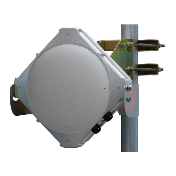
Page 17: Pole Mounting
GE60 Installation Manual Attach the radio yoke to the mount, with brass shim in-between, using 2 each of the supplied ⅜-16 x ¾ bolts, ⅜ lock washers, and ⅜ flat washers. Tighten the bolts just enough that the yoke can move back and forth without binding. - Page 18 GE60 Installation Manual Figure 3-2: Mount with Radio Yoke in ‘Pole Mount’ Configuration Figure 3-3: Side view of mount with Radio Yoke in ‘Pole Mount’ Configuration 580-00505, rev 0.4 18 of 30 PRELIMINARY...
- Page 19 GE60 Installation Manual 6.25 inches (15.9 cm) 3.13 inches (8.0 cm) Figure 3-4: Template Radio Mounting bolts 580-00505, rev 0.4 19 of 30 PRELIMINARY...
-
Page 20: Radio Installation
GE60 Installation Manual 3.6 Radio Installation Remove the up/down adjustment bolts from the radio. Place the radio in the yoke— the two up/down pivot bolts should rest in the U’s cut in the yoke. Note that when the radio comes from the factory, the mounting plates are in the “vertical polarization”... - Page 21 GE60 Installation Manual Figure 3-5: Inserting Radio Into Yoke Reinsert the up/down adjustment bolts, through the channel in the yoke. Tighten the up/down pivot bolts enough such that the finger cam is behind the tab at the front of the yoke. Turn the finger cam clockwise until tight. With the cam tightened, the pivot bolt is prevented from any front/back movement.
-
Page 22: Cable Installation
GE60 Installation Manual 3.7 Cable Installation Fiber Cabling Install a duplex multi-mode fiber from the radio to the network termination equipment (switch or router with 1000Base-SX port). The connectors on the radio end of fiber require LC connectors; the connectors on the switch/router end should mate to the network equipment. - Page 23 GE60 Installation Manual Figure 3-8: Inside view of fiber and power cable connected Note that the fiber cable is inserted through the “straight-through fitting” on the left and the power cable is inserted through the fitting on the right. Both the cables have been looped around the inside of the enclosure to minimize tension on the cables when connected to the radio.
-
Page 24: Visual Alignment
GE60 Installation Manual 3.8 Visual Alignment Tighten mounting bolts just enough to allow radio to pivot up/down and right/left with minimal effort. Tilt the radio so that it is roughly point towards the other end of the link. Insert the Visual Alignment Tool (VAT) into one of the 4 holes in the front (antenna) face of the RADIO. - Page 25 GE60 Installation Manual Radio at far end of link The alignment aids need to be in a straight line. Target, other radio, is placed at top of middle aid. Right Radio at far end of link Aiming Too low Wrong Tighten the left/right adjustment bolt enough to prevent accidental movement of the radio.
- Page 26 GE60 Installation Manual 10. Remove the plastic cover on the back of the radio that is secured with a cap bolt. Look to see that the “Link Up” LED is lit. This LED is lit when the two radios are aligned and passing data to one another.
- Page 27 GE60 Installation Manual 3.9 Fine Alignment -- Optional The fine alignment procedure uses Receive Signal Strength Indication (RSSI) voltage generated by the radio’s receiver. Since this voltage reacts to the power of the received signal, it is not influenced by the machining/manufacturing tolerances seen with mechanical parts.
- Page 28 GE60 Installation Manual Tilt the radio left and right until the maximum reading is achieved on the voltmeter. Tighten the left/right adjustment bolt to prevent movement in this axis. Tilt the radio up and down until the maximum reading is achieved on the voltmeter.
-
Page 29: Operation
Figure 4-1: Link Up, Fiber and Pwr (Power) LED’s indicating link is up and operating The GE60 radio itself does not require periodic maintenance. However, each end of the link should be periodically inspected for visible damage or excessive accumulation of dirt. -
Page 30: Troubleshooting
GE60 Installation Manual 5 Troubleshooting Radio link troubleshooting process Is the Pwr LED green? Is the Supply voltage at the Is the Fiber LED radio, with radio green? connected, >+13.5v and <+24.0v? Check the power supply Check the polarity of Check the fibers to the output.
Need help?
Do you have a question about the GE60 and is the answer not in the manual?
Questions and answers