
Summary of Contents for Simpson Electric 479
- Page 1 OPERATOR’S MANUAL MODEL 479 FM-TV SIGNAL GENERATOR ELECTRIC SIMPSON COMPANY St., 5200 W. ICinzie Chicago 44, Illinois, ES 9-1121 In Canadz. Bach-Simpson. Ltd., London, Ontario Simpson Electrk Co., Chkogo 44, IIInos...
-
Page 2: Audio Generator
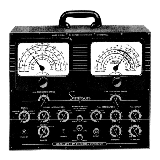
MODEL .479 TV -FM SIGNAL GEHERATOD A. M. GENERATOR F.M. GENERATOR AUDIO GENERATOR CRYSTAL CALLBRATOR THE MODEL 479 TV-FM SIGNAL GENERATOR FIG. 1. - Page 3 ‘14p ,uLjc frMP &L...
- Page 4 1000 division logging scale. quency within the range of the generator. Everything possible has been done to make the Model 479 the most accurate, flex ible and convenient instrument available. Each part of this instrument has been con sidered carefully for long life and stability.
- Page 5 The POWER switch lower enter controls the power input to both sections of the Model 479. When the switch is in the OFF position the entire instrument is turned off. In the STAND BY position, all the tube filaments are turned on but no plate voltage is The green light is on for applied.
- Page 6 +h1’ 4’r, CALIBRATION PROCEDURE FOR DETERMINING TUNABLE FREQUENCIES WITH CRYSTAL ACCURACY The Model 479 has two precision vernier dials; one is used for the a-rn generator a-mgenerator can be used as a marker and the other for the f-rn generator.
- Page 7 FIG. MODEL 479 AM-FM LOGGING DIAL Figure 2 is an illustration of the logging arcs as they are used in both a-rn The upper arc of each dial is divided into f-rn generator dials.
- Page 8 TABLE I CRYSTAL CALIBRATING POINTS BAND C BAND B BAND A VAR. XTL. VAR. XTL. VAR. XTL. FUNDAMENTAL HARMONIC OSC. OSC. OSC. FUNDAMENTAL HARMONIC OSC. OSC. FUNDAMENTAL HARMONIC OSC. MEGACYCLES MEGACYCLES HARM. HARM. HARM. MEGACYCLES HARM. HARM. MEDACYCLES MEGACYCLES HARM. MEGACYCLES *333 *1500...
- Page 9 VERT. AMPL. and HORIZ. AMPL. cables con nected. Have the POWER switch in either STAND BY or OPERATE position for at least 15 minutes before beginning the calibration to allow the Model 479 to warm up, and set it in the OPERATE position to calibrate.
- Page 10 VERT. AMPL. and HORIZ. AMPL. cables connected. Have the POWER switch in either STAND BY or OPERATE position for at least 15 minutes before beginning the calibration to allow the Model 479 to warm up, and set it in the OPERATE position to calibrate.
- Page 11 In the example, using the .75 mc. deviation from 20 megacycles, 3.19 divisions. 3. If the lower check point was used to determine Di in step 2, add D1 to the log ging scale setting for this check point; or if the higher checkpoint was used to determine Di in step 2, subtract Dl fromthe logging scale settingfor this check point.
- Page 12 3/4 of maximum. Some receivers require a battery bias to simulate normal AGG. 4. Allow the receiver and the Model 479 to warm up for about 15 minutes be fore attempting to make any adjustments. The Model 479 will not require additional warm up time if the POWER switch has been left in the STAND BY position.
- Page 13 Center the trace horizontally and vertically. 8. On the Model 479, set the controls as follows: F.M. GENERATOR RANGE switchatOFF: A.M. GENERATOR RANGE switch to B; SIGNAL switch to GAL., and SIGNAL ATTENUATORS low.
- Page 14 L3 point 2 for a minimum indication. 15. Leave the Model 479 set at 21.25 mc. and adjust the accompanying sound trap L9 point 3 for a minimum indication. 16. Set the logging scale to the point recordedfor 27.25 mc. and adjust the ad jacent channel sound trap L5 point 4 for a minimum indication.
- Page 15 a5.75 25,7 MPROPERL’ ALIGNED ftPRO?ERLY PLtGt4ED STAGGER TUNED PICTURE IF RESPONSE FIG. 5. 26. Compare the pattern with the one shown in the manufacturer’s instruc tions. Figure 5 shows an example of an i-f response curve. If the system has been aligned properly, it should resemble figure 5A.
- Page 16 Tr:J ITTE > 2’342526I FREQUENCY MC FIG. 6 VIDEO ALIGNMENT CURVES BAND PASS TYPE Move the OUTPUT cable to the grid of the preceding stage. Adjust the secondary of this i-f transformer fora peak at 23.75 mc. and the primary for a peak at 26.75 mc. There is no coupling condenser adjustment for this stage.
- Page 17 Set up the Model 479 in accordance with general instructions and use an oscilloscope to observe the results. Use the 6O sweep available through the HORIZ.
- Page 18 1. Connect the HORIZ. AMPL. cable and the VERT. AMPL. cable to the input terminals of the associated oscilloscope. and ground see 2. Connect the Model 479 OUTPUT cable between point "C See table 2 for data on the termination box figure 8. Use any desired termination.
- Page 19 curve is not centered on the trac-e, reset the CENTER FREQUENCY pointer to center the pattern. Advance the BLANKING control to produce a pattern as shown in figure 10; this is a single curve with a base line through it. FIG.
- Page 20 –1 t tt-r-ht-+-tt FIG. 12. SOUND I-F RESPONSE 16. Adjust L7 and L6 of figure 8 for a symmetrical response of maximum height similar to figure 12. The marker should appear at the center. Keep the F.M. ATTEN UATORS set as low as possible to avoid overloading and keep the SIGNAL ATTEN UATORS set low to avoid distortion of the response curve at the marker point.
- Page 21 TELEVISION TUNER ALIGNMENT Many of the present day television sets use an r-f tuning unit produced by Standard Coil Products Co. This unit contains a 12-position rotary channel selector together with a stage of r-f amplification, an r-f oscillator, and an r-f mixer. The components are matched for the purpose of transferring the modulation on the tuned signal to an intermediate frequency.
- Page 22 is on one slope of the curve ata 50% response point, and the center sound carrier is on the other side of the curve at a 5% response point. The same pair of wave shapes need to be produced for each of the 12 channels. Each channel has a pair of tuned cir cuits with switch points which make all the necessary connections to tune both the re ceived signal and the local oscillator for the frequencies necessaryfor the channel.
-
Page 23: Tuner Alignment
VIDEO CARRIER SOUND CAIRIER DIFFERENCE IN HEIGHT OF PEAKS MARKER /H0ULD NOT EXCEED 3db OR 30% 3db MUMUM3O% ATA5T 26db DIP 5HOULDOT AGdbO POINT EXCEED 3db OR 30% OF TOTAL HEIGHT :EORRtER MARKER MAR K ER 5KIRT CURVE WILL NOT BE VIBLE UHLES5 FULL A MEASURED FROM HIGHE3T PEAK GENERATOR SWEEP WIDTH EXTEND5 BEYOND 10 MC. - Page 24 2. Connect the SIGNAL INPUT cable across the output of the demodulator stage point uA in figure 8. 3. Connect the OUTPUT cable through its matching network to the antenna terminals of the receiver. Connect the termination box according to the data in table 2 to provide the correct input for the receiver.
- Page 25 The OUTPUT cable for the Model 479 has a termination box built on the probe end to facilitate matching these impedances. See figure 16 and table 2 for an outline drawing of the probe and some of the possible connections.
- Page 26 Suppose 150 ohms were desired. to provide the proper termination for the Model 479. Then connect a 75 ohm resistor from terminal 6 to terminal 7, a jumper from 7 to 8 to 9, a jumper from 3 to 4, and a 50 ohm resistor between terminals 2 and 3.
-
Page 27: Signal Tracing
Figure 17 shows the arrangement of components in the Simpson High frequency Probe, No. 10-890025, which is available to owners of the Model 479 at a nominal cost. Connect this probe to the SIGNAL INPUT of the Model 479 to trace the signal through an f-m or television receiver. - Page 28 FIG. 18. REAR VIEW OF MODEL 479. CASE AND SHIELDING REMOVED The chassis of the Model 479 is mounted into its case with 18 screws around the Removing these 18 screws and 2 on the back at the line cord edge of the front panel.
- Page 29 1. With the back and top shields removed frombothoscillator sections, turn the POWER switch to OPERATE and allow the Model 479 to warmup for at least 15 minutes. 2. Connect the VERT. AMPL. and HORIZ. AMPL. cables to the vertical horizontal inputs of an oscilloscope.
- Page 30 Lt. Set the A.M. GENERATOR RANGE to B, SIGNAL switch to CAL,, and Tune the A.M. Generator to its 70 mc. SIGNAL ATTENUATORpotentiorneter to 6. calibration check point. Turn the SIGNAL switch to UNMOD. R.F, and the SIGNAL ATTENUATOR potentiometer to 10. i Tune the F.M.
- Page 31 Go back to step 19 and repeat the 140 mc. oscillator adjustment. 33. Remove the crystal diode and replace all shielding. The Model 479 oscil lators are now aligned within the close tolerances to which they were adjusted when it was manufactured.
-
Page 32: Warranty
Should your Model 479 fail to give satisfactory service due to reparable damage, it can be returned to the factory for repairs. Always accompany any equipment sent in for repair with a statement indicating where the trouble is;... -
Page 33: Parts List
MODEL 479 PARTS LIST CIRCUiT SI MPSON PART NUMR ER REFERENCE Capacitor 8ZOOuuf mica 1-113911 Capacitor .OSuf 400 V. paper 1-113899 Capacitor 8ZOOuuf mica 1-1 13911 Capacitor .OSuf 400 V.paper 1-113899 Capacitor S000uuf ceramic 1-113913 Capacitor .O2uf 400 V paper 1-113898 Capacitor 4.5-Z5uuf trimmer... - Page 34 PARTS LIST MODEL 479 CIRCUIT SIMPSON REFERENCE DESCRIPTION PART NUMBER 85uh choke coil 10-890034 Oscillator coil, A.M. Band 10-890033 NC" Oscillator coil, A.M. Band "A" 10-890031 Oscillator coil, A.M, Band 10-890032 "B" Coil assembly, F.M. tuner 10-890028 Oscillator coil, l4Omc.
- Page 35 PARTS LIST MODEL 479 C I RCU I T St MPSON REFERENCE 0 E Sc RI PT 10 N PART NLJM8ER Resistor, 75 ohm 1/2w. 5% 1-114113 1/2w. Resistor, 750 ohm 1- 111684 R4 8 i/zw. Resistor, 91 ohm 1-113923 Resistor, 750 ohm 1/2W.
Need help?
Do you have a question about the 479 and is the answer not in the manual?
Questions and answers