Table of Contents
Advertisement
Advertisement
Table of Contents

Related Manuals for Mercoid 3100


Summary of Contents for Mercoid 3100
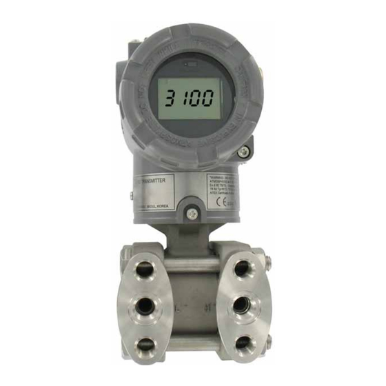
- Page 1 Bulletin P-3100 Series 3100 Explosion-Proof Differential Pressure Transmitter Specifications - Installation and Operating Instructions DWYER INSTRUMENTS, INC. Phone: 219/879-8000 www.dwyer-inst.com P.O. BOX 373 • MICHIGAN CITY, INDIANA 46361, U.S.A. Fax: 219/872-9057 e-mail: info@dwyer-inst.com...
-
Page 2: Table Of Contents
Chapter 6. Maintenance 6.1 Overview 6.2 Safety Messages 6.3 Hardware Diagnosis 6.4 Hardware Maintenance Appendix I 3100 Smart Pressure Transmitter LCD Display Code Appendix II 3100 Smart Pressure Transmitter HART ® Communicator User’s Guide Appendix III 3100 Smart Pressure Transmitter Series User Guide HART ®... -
Page 3: Using This Manual
Chapter 1 Introduction The 3100 Smart Pressure Transmitter is calibrated at the factory before shipping. To ensure correct and efficient use of the instrument, please read the manual thoroughly and fully understand how to operate the instrument before operation. 1. The contents of this manual are subject to change without prior notice. -
Page 4: Overview Of Transmitter
Smart Pressure Transmitter is a microprocessor based pressure transmitter with a capacitance sensor optimized for draft measurement. The Model 3100 has a true draft analog range from 0 to 20 mA. This transmitter is explosion-proof, high precision accuracy, reliability and has digital communication for remote communication system. -
Page 5: Chapter 2. Handling Cautions
Chapter 2 Handling Cautions This chapter consists of cautions for transmitter handling, storage, installation, insulation and explosion structure, etc. Step Job Details Instrument Unpacking - Unpack transmitter packing Model and - Make sure the transmitter nameplate matches the model number on the P.O. -
Page 6: Models And Specifications Check
2.1 Unpacking 2.5 Calibration after Installation When moving the transmitter to the installation site, keep it in the 1. Sensor Zero Trim should be done after transmitter is installed, original packaging. Unpack the transmitter at the installation site to because the zero point is not configured for mounting status. avoid damage on the way. -
Page 7: Emc Conformity Standards
3.1 Overview 2. Turn OFF the insulation tester. Then connect the This Chapter contains information on operating the Model 3100. insulation tester plus (+) lead-wire to the shorted SUPPLY Tasks that should be performed on the bench prior to installation are terminals and the minus (-) lead wire to the grounding explained in this chapter. -
Page 8: Configuration Of Alarm And Security Jumper Procedures
Down Fail U or D Figure 3-3. CPU Module Fail Mode, EEPROM-Write Selection Jumper Switch DOWN The 3100 has two security settings. 1. Security Jumper: the transmitter configuration parameters are protected. 1. WR_EN (EEPROM Write Enable) DOWN : ENABLE 2. Physically removing Zero and Span Magnetic Buttons: you are : DISABLE unable to regulate zero and span locally. -
Page 9: Configuration Of Zero And Span Procedure
3.7 Configuration of Zero and Span Procedures Caution: 30 seconds without any action, the button function will The ZERO and SPAN Buttons are under the transmitter’s return to normal operation. nameplate. The ZERO, SPAN, ZERO TRIM, ZERO ADJ, Units, Range, Dampening, LCD and decimal set functions are configurable 4. - Page 10 6. Press the Span button until the Zero Adjustment current directly from the transmitter. Since the 3100 is a two wire message appears. loop powered transmitter, it requires an external loop power supply ®...
-
Page 11: Chapter 4. Installation
• Avoid contact with the leads and terminals. [Figure 4-1 Installation Flow Chart] 4.4 Commissioning on the Bench with Hand-Held Terminal The 3100 Pressure Transmitter can be commissioned before and 4.5 General Considerations after installation. Commissioning is easier if the transmitter is The transmitter can be mounted near the process to minimize piping. -
Page 12: Wiring
4.6.1 Power Supply The 3100 Pressure Transmitter requires an 11.9 – 45 VDC power supply. A 250 ~ 550Ω (24 VDC) loop resistance is recommended for HART ® communication. Loop resistance is the sum of the resistance in the loop. - Page 13 There are ground terminals on the inside and outside of the transmitter. Either of these terminals may be used. Use 600V insulated PVC wire for grounding. 3100 Smart Pressure Transmitter Internal and External Ground Terminal Figure 4-4a Typical Mounting using Flexible Metal Conduit 4.7.6 Power Supply Voltage and Load Resistance...
-
Page 14: Mechanical Considerations
4.8 Mechanical Considerations 4.9 Environmental Considerations Figure 4-6 is a dimensional drawing for the 3100. Figure 4-7 shows 4.9.1 Ambient Temperature how the A-630 angle bracket is mounted to a pipe. The transmitter ambient temperature range is 4 to 180°F (-20 to 60°C). -
Page 15: Basic Setup
5.4.1 Process Variable 5.6 Detailed Setup There are two process variables in the 3100 Smart Pressure Transmitter. The primary variable and temperature compensated 5.6.1 Set Fail Mode SV (Second Variable), the PV value outputs the 4~20mA analog When the sensor or microprocessor is not operating properly, the value. -
Page 16: Calibration
• Only qualified personnel can configure and wire the over a specific pressure range. Rerange provides ability to readjust 3100 Smart Pressure Transmitter. the 4~20 mA points sensor inputs. 5.9.1 Sensor Trim The Sensor trim function adjusts the A/D signal conversion within the transmitter sensor electronics and determines how it digitally interprets any pressure changes applied to the sensor inputs. -
Page 17: Hardware Diagnosis
Table 6.1 Troubleshooting 6.4 Hardware Maintenance The Mercoid ® 3100 Smart Transmitter has no moving parts and requires little maintenance. If a transmitter fails, it must be returned to Dwyer Instruments, Inc. for inspection, repair, or replacement. 6.4.1 Test Terminals The test terminals are marked TEST on the terminal block. - Page 18 Figure 6-1 Test Terminals 6.4.2 Disassembling the Housing The transmitter is designed with dual-compartment housing; one contains the electronics module, and the other contains all wiring terminals and communication terminal. Figure 6-2 Structure of Housing 6.4.2.2 Fail Mode Jumper Switch and EEPROM-Write Fail-mode jumper switch and EEPROM-Write is located behind the front cover.
-
Page 19: 3100 Smart Pressure Transmitter Lcd Display Code
Appendix I 3100 SMART PRESSURE TRANSMITTER - LCD DISPLAY CODE Description Message ADJ-U Zero adjustment value – used to configure transmitter when it is out of range (on higher side) ADJ-L Zero adjustment value – used to configure transmitter when it is out of range (on low side) - Page 20 ©Copyright 2010 Dwyer Instruments, Inc. Printed in U.S.A. 3/10 FR# RA-443807-00 DWYER INSTRUMENTS, INC. Phone: 219/879-8000 www.dwyer-inst.com P.O. BOX 373 • MICHIGAN CITY, INDIANA 46361, U.S.A. Fax: 219/872-9057 e-mail: info@dwyer-inst.com...
Need help?
Do you have a question about the 3100 and is the answer not in the manual?
Questions and answers