Table of Contents
Advertisement
Available languages
Available languages
Quick Links
WARNING
Improper installation,
adjustment, alteration, service or
maintenance can cause injury or
property damage.
Read this instruction manual
thoroughly before installing or
servicing this equipment.
WARNING
1. Do not store or use gasoline or
other flammable vapors and
liquids in the vicinity of this or
any other appliance,
2. An LP tank not connected for use
should not be stored in the
vicinity of this or any other
appliance.
DANGER
If you smell gas:
1. Shut off gas to the appliance.
2. Extinguish any open flames.
3. Open the lid.
4. If the odor continues, keep away
from the appliance and
immediately call your gas supplier
or fire department.
WARNING
For Outdoor Use Only
ATTACH YOUR RECEIPT HERE
Serial Number
Questions, problems, missing parts? Before returning to your retailer, call our customer service
department at 1-888-804-7455, 8 a.m. - 6 p.m., EST, Monday - Thursday, 8 a.m. - 5 p.m., EST, Friday.
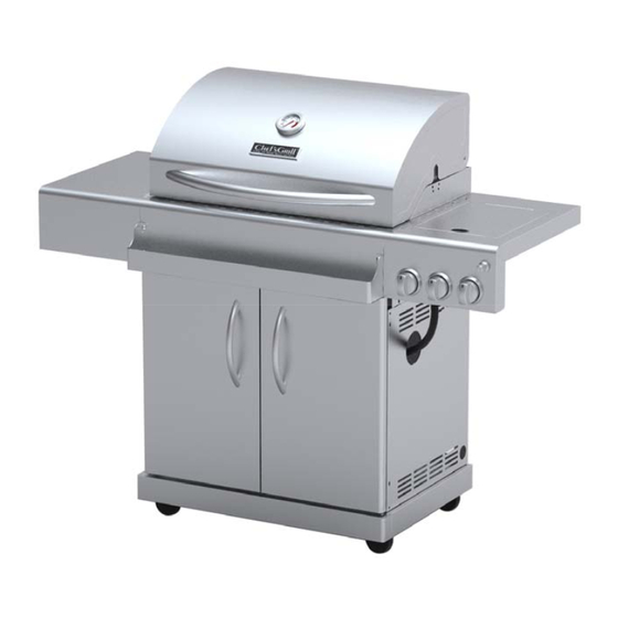
2-Burner IR-TEC
Liquid Propane Gas Grill
Purchase Date
Infrared
TM
MODEL: IR2818-1
Français p.31
Español p.61
Advertisement
Table of Contents

Subscribe to Our Youtube Channel
Related Manuals for Chef's Grill IR2818-1

Summary of Contents for Chef's Grill IR2818-1
- Page 1 2-Burner IR-TEC Infrared Liquid Propane Gas Grill MODEL: IR2818-1 Français p.31 WARNING Español p.61 Improper installation, adjustment, alteration, service or maintenance can cause injury or property damage. Read this instruction manual thoroughly before installing or servicing this equipment. WARNING 1. Do not store or use gasoline or...
-
Page 2: Safety Symbols
Installation Safety Precautions • Use grill, as purchased, only with LP (propane) gas and the regulator/valve assembly supplied. A conversion kit must be purchased for use with natural gas. If you smell gas: • Grill installation must conform with local codes, or in their absence of local codes, with either the National Fuel Gas 1. -
Page 3: Table Of Contents
TABLE OF CONTENTS WARNING For Your Safety....... . . 2 CALIFORNIA PROPOSITION 65 Grill Service Center. - Page 4 WARRANTY CHEF’S GRILL LIMITED WARRANTY WITH PROOF OF SALE, the following warranty coverage applies when this appliance is correctly installed, operated and maintained according to all supplied instructions. ONE YEAR Overall Warranty: From the date of sale this appliance is warranted against defects in material or workmanship.
-
Page 5: Use And Care
• Do not store an LP tank in an area where children play. USE AND CARE LP Cylinder • The LP cylinder used with your grill must meet the following requirements: • Use LP cylinders only with these required measurements: 12" (30.5cm) (diameter) x 18"... - Page 6 LP Tank Exchange Connecting Regulator To The LP Tank •Many retailers that sell grills offer you the option of replacing 1. LP tank must be properly secured onto grill. (Refer to your empty LP tank through an exchange service. Use only assembly section.) those reputable exchange companies that inspect, precision 2.
- Page 7 Leak Testing Valves, Hose and Regulator 1. Turn all grill control knobs to OFF. 2. Be sure regulator is tightly connected to LP tank. 3. Completely open LP tank valve by turning OPD hand wheel counterclockwise. If you hear a rushing sound, turn gas off immediately.
- Page 8 Safety Tips Before opening LP cylinder valve, check the coupling nut for tightness. When grill is not in use, turn off all control knobs and LP For Safe Use of Your Grill and to Avoid Serious cylinder valve. Injury: Never move grill while in operation or still hot. •...
- Page 9 Ignitor Lighting the Grill Main Burner Match Lighting 1. Read instructions before lighting your grill. Do not lean over grill while lighting. 2. Open lid during lighting. 1. Open lid during lighting. 3. Open LP cylinder or natural gas valve. 2.
- Page 10 Turning Grill Off • Cooking surfaces: If a bristle brush is used to clean any of the grill cooking surfaces, ensure no loose bristles remain on •Turn all knobs to position. Turn LP cylinder off by turning cooking surfaces prior to grilling. It is not recommended to hand-wheel clockwise to a full stop.
- Page 11 Storing Your Grill WARNING: To ensure that it is safe to eat, food must be cooked to the minimum internal temperatures listed in the table •Clean cooking grates. below. •Store in dry location. •When LP cylinder is connected to grill, store outdoors in a wellventilated space and out of reach of children.
- Page 12 Gas Requirements Care and Maintenance Time Table Chart LP Gas Frequency Based If your grill is for LP Gas, the regulator supplied is set for Grill Item Cleaning Method on Normal Use an 11-in. water column (WC) and is for use with LP gas Painted surface Twice yearly Car wax...
-
Page 13: Natural Gas Conversion Kit
Kit (sold separately) are required for the conversion. Natural gas conversion kit Model # NGKIT-01 (Manufacturer Part No.: IR2818-1-KIT) 2. Insert plug and release sleeve. 3. Push plug until sleeve snaps forward. (Gas will flow automatically. Failure to connect plug properly to socket will inhibit gas flow to the appliance.) -
Page 14: Parts List
IR2818-1 TEMPERATURE GAUGE SLEEVE E3518-00-4009 HARDWARE PACK HARDWARE MAIN GRID RB2818ST-00-2001 PRODUCT MANUAL IR2818-1 - MANUAL WARMING RACK 2818-2T-2002 HEAT TENT IR2818-00-2004 If you are missing hardware or have damaged parts after REFLECTOR IR2818-00-2041 unpacking grill, call 1-888-804-7455 for replacement. -
Page 15: Parts Diagram
PARTS DIAGRAM ○ ○ ○ ○ ○ ○ ○ ○ ○ ○ ○ ○ ○ ○ ○ ○ ○ ○ ○ ○ ○ ○ ○ ○ ○ ○ ○ ○ ○ ○ ○ ○ ○ ○ ○ ○ ○ ○ ○... -
Page 16: Assembly
UNPACKING After removing all parts and hardware pack from the top of the shipping box, and when the only part showing is the grill head, use a ox cutting knife to slice down the sides of the box. Be careful of staples along shipping box edges. Remove the corner supports from the box and the styrofoam side pieces from the grill head. - Page 17 Attach the left panel and rear panel to the bottom panel. There are 3 screws for the rear panel, 5 screws for the bottom panel. 3/16-24 x 1/2″Screw Qty. 8 Left Panel Rear Panel Attach the right panel to the bottom panel and rear panel with 5 screws. There are 2 screws for bottom panel and 3 screws for rear panel.
- Page 18 Slide the tank ring bracket onto the end of the tank ring. Attach the bracket to the rear panel with 2 screws. Tank Ring Bracket 1/4-20 x 5/8″Screw Qty. 2 Tank Ring Loosen the two screws in the right and left side panel brackets 3 to 4 turns. Insert the screws through the 2 holes at the base of each side panel and slide the bracket down until it stops.
- Page 19 Attach the beam to the side panels with 4 screws. 3/16-24 x 1/2″Screw Qty. 4 Beam Attach the drip cup support to the rear panel and beam with 4 screws, 2 screws for the rear panel and 2 screws for the beam. 3/16-24 x 1/2″Screw Qty.
- Page 20 Put the drip cup on the drip cup support. Drip Cup Cut tie wraps holding regulator underneath grill head control panel. Be careful not to cut igniter wires or the tie wraps holding the igniter wires in place. With the aid of an assistant, lift and place grill head onto cart. Grill head sides go over attachment tabs on cart.
- Page 21 For each door, insert bottom hinge pin into hole on bottom panel. Push down on top hinge pin to insert into hole in bottom corner of control panel. Adjust magnets on the bottom panel and front beam to align the magnets with doors, and then tighten magnet screws.
- Page 22 Side Burner Shelf Loosen the two screws attached in the right panel of the burner box 3 to 4 turns as shown. Hang the side burner shelf by the slotted holes in its side onto the two loosened screws. Fasten the side burner shelf with two 1/4-20 x 5/8″screws as shown.
- Page 23 Ignition Wires Plug the infrared burner ignition pin wires and side burner ignition pin wire into the sockets in the igniter as shown. Side burner ignition pin wire Infrared burner ignition pin wire Attach the condiment box to the control panel by the slotted holes. Condiment box...
- Page 24 Adjust the drip tray until it is secure in the middle bottom of the fire box. This is an "easy clean" tray; it slides easily out of the back of the grill for cleaning. WARNING: Make sure the drip tray and drip cup are properly installed before turning burners on. Drip tray Drip tray Install the Reflector, Heat Diffusers, Cooking Grates, Side Burner Grate, Warming Rack and Battery...
- Page 25 LP Tank Installation Open front doors of cart. Set base of tank into tank support with tank collar opening facing to the right as shown. Set the tank ring hold the tank collar. Connect the regulator to tank (see page 5 of Use and Care section).
-
Page 26: Natural Gas Conversion Instructions
NATURAL GAS CONVERSION INSTRUCTIONS The NGKIT-01 contains orifices for various grill models. Please Model Main burner Side burner select the orifices as listed and discard the rest. Follow the 1.81mm 1.31mm conversion instruction provided with the kit. 2 pc 1 pc Main Burner Conversion 1. - Page 27 Side Burner Conversion 1. Loosen the side burner screws to expose the side burner valve. Insert the tool onto the valve and unscrew orifice from end of valve. Put the new orifice into the orifice removal tool and tighten the new orifice into the valve.
- Page 28 Natural Gas Hose Connection Remove the LP gas hose and regulator using a wrench, and attach the natural gas hose in its place. (Fig. 5) Fig. 5 Adjust valve control screw 1. Pull all the knobs off of valve stems. Adjust the screw in the valve hole using the flathead screwdriver.
-
Page 29: Troubleshooting
TROUBLESHOOTING Problem Possible Cause Corrective Action 1. Reconnect the ignition wire to the 1. The ignition wire came off electrical igniter. the electrical igniter. 2. Loosen the ignition pin and adjust the 2. The distance between the distance, then fasten it again. ignition pin and the burner is greater than 0.1-0.2 inch(side burner). - Page 30 Problem Possible Cause Corrective Action 1. LP tank is empty. 1. Refill the LP Tank. 2. Burner is not aligned with 2. Install the burner correctly. Burner blows out the control valve. 3. Gas supply is not sufficient. 3. Check the gas supply hose and make sure there are no leaks and no knots.
- Page 31 2-BRÛLEUR IR-TEC INFRAROUGE PROPANE LIQUIDE GAZ GRILL MODÈLE: IR2818-1 AVERTISSEMENT Une installation, un ajustement, une modification, une utilisation ou un entretien inadéquat peut causer des blessures ou des dommages matériels. Lisez attentivement le manuel d’instructions avant d’installer ou d’entretenir cet appareil.
- Page 32 Mesures de sécurité pour l’installation • Utilisez le barbecue, tel qu’il a été acheté, seulement avec du gaz propane liquide et l’ensemble régulateur/soupape fourni. Vous devez vous procurer un nécessaire de Si vous sentez une odeur de gaz : conversion afin que le barbecue puisse fonctionner au gaz naturel.
- Page 33 TABLE DES MATIÈRES AVERTISSEMENT Pour votre sécurité.............29 PROPOSITION 65 DE L’ÉTAT DE CALIFORNIE 1. Les produits dérives de la combustion produits Centre de services pour barbecues........29 lors de l’utilisation du présent produit Renseignements relatifs à la garantie........29 contiennent des produits chimiques reconnus Symboles de sécurité............29 par l’État de Californie comme étant Mesures de sécurité...
- Page 34 GARANTIE GARANTIE LIMITÉE Avec PREUVE DE VENTE à l’appui, la garantie suivante s’applique lorsque cet appareil est correctement installé, utilisé et entretenu conformément à toutes les instructions fournies. VALIDE POUR UN AN à compter de la date de vente de cet appareil, cette garantie couvre les défauts de matériaux ou de fabrication.
- Page 35 UTILISATION ET ENTRETIEN • N’entreposez pas de bouteille de GPL dans un endroit où des enfants jouent. Bouteille de GPL • La bouteille de GPL utilisée avec votre barbecue doit répondre aux exigences suivantes : • Utilisez seulement une bouteille de GPL respectant les mesures •...
- Page 36 Échange de bouteille de GPL Connexion du régulateur à la bouteille de GPL • Plusieurs détaillants de barbecues offrent la possibilité de 1. La bouteille de GPL doit être reliée au barbecue de façon profiter d'un service d’échange de bouteilles vides. Ne faites sécuritaire.
- Page 37 Essai d’étanchéité des robinets, des tuyaux et du régulateur 1. Tournez tous les boutons de commande du barbecue en position d’arrêt (OFF). Alignez 2. Assurez-vous que le régulateur est relié de façon étanche au robinet de la bouteille de GPL. 3.
- Page 38 Conseils de sécurité AVERTISSEMENT Avant d’ouvrir le robinet de la bouteille de GPL, vérifiez que l’écrou d’accouplement est bien serré. Pour utiliser votre barbecue en toute sécurité et pour Lorsque vous n’utilisez pas le barbecue, tournez tous les éviter des blessures graves : boutons de commande et le robinet de la bouteille de GPL en •...
- Page 39 5. Si l’allumage ne se produit pas dans les 5 secondes, fermez le Brûleur de latéral allumette bouton de commande du brûleur, attendez 5 minutes pour que le 1. Ouvrez le couvercle du brûleur latéral. Allumez le gaz au GPL. gaz puisse se dissiper et répétez les étapes d'allumage.
- Page 40 Vérification des tuyaux Séparez : Séparez la viande et la volaille crues des aliments prêts • Avant chaque utilisation, examinez les tuyaux pour détecter toute à être consommés afin d’éviter toute contamination croisée. trace de coupures ou d’usure. Utilisez un plateau et des ustensiles propres pour retirer les Remplacez les tuyaux endommagés avant d’utiliser le barbecue.
- Page 41 Exigences relatives au gaz le poulet. Fermez le couvercle pour la cuisson indirecte ou au tournebroche. Gaz de pétrole liquéfié Ne laissez JAMAIS le barbecue sans surveillance durant Si vous avez un barbecue fonctionnant au gaz propane la cuisson. liquide, le régulateur fourni sera réglé pour une pression de sortie de 11 po de colonne d’eau (C.E.) et devra être Une fois la cuisson terminée, fermez le couvercle et utilisé...
- Page 42 2. Insérez la fiche et relâchez le manchon. Modèle n° NGKIT-01 3. Poussez la fiche jusqu’à ce que le manchon (Référence fabricant : IR2818-1-KIT) s’enclenche vers l’avant. (L’alimentation en gaz commencera automatiquement. Si la fiche n’est pas branchée correctement dans la douille, il n’y aura pas de débit de gaz vers l’appareil.)
- Page 43 IR2818-00-2143 2518-4C-8012 INDICATEUR DE TEMPÉRATURE SUPPORT DE CHALEUR TENTE IR2818-00-2102 3218LTN-00-4001 TEMPERATURE GAUGE LUNETTE IR2818-1- MATERIEL PAQUET E3518-00-4009 TEMPERATURE GAUGE MANCHES HARDWARE IR2818-1 - RB2818ST-00-2001 GRID MAIN MANUEL DU PRODUIT MANUAL 2818-2T-2002 RÉCHAUFFEMENT RACK IR2818-00-2004 CHALEUR TENTE IR2818-00-2041 RÉFLECTEUR IR2818-00-2000 BRÛLEUR BOX...
- Page 44 SCHÉMA DES PIÈCES ○ ○ ○ ○ ○ ○ ○ ○ ○ ○ ○ ○ ○ ○ ○ ○ ○ ○ ○ ○ ○ ○ ○ ○ ○ ○ ○ ○ ○ ○ ○ ○ ○ ○ ○ ○ ○ ○...
- Page 45 DÉBALLAGE Après avoir déballer toutes les pièces et accessoires du haut de la boîte d'expédition, et que seul le dessus du barbecue paraît, utilisez un couteau et coupez les côtés de la boîte pour l'aplatir. Faites attention aux agrafes le long des bords de la boîte d'expédition.
- Page 46 Attach the left panel and rear panel to the bottom panel. There are 3 screws for the rear panel, 5 screws for the bottom panel. 3/16-24 x 1/2″Screw Qty. 8 Left Panel Rear Panel Attach the right panel to the bottom panel and rear panel with 5 screws. There are 2 screws for bottom panel and 3 screws for rear panel.
- Page 47 Slide the tank ring bracket onto the end of the tank ring. Attach the bracket to the rear panel with 2 screws. Tank Ring Bracket 1/4-20 x 5/8″Screw Qty. 2 Tank Ring Loosen the two screws in the right and left side panel brackets 3 to 4 turns. Insert the screws through the 2 holes at the base of each side panel and slide the bracket down until it stops.
- Page 48 Attach the beam to the side panels with 4 screws. 3/16-24 x 1/2″Screw Qty. 4 Beam Attach the drip cup support to the rear panel and beam with 4 screws, 2 screws for the rear panel and 2 screws for the beam. 3/16-24 x 1/2″Screw Qty.
- Page 49 Put the drip cup on the drip cup support. Drip Cup Cut tie wraps holding regulator underneath grill head control panel. Be careful not to cut igniter wires or the tie wraps holding the igniter wires in place. With the aid of an assistant, lift and place grill head onto cart. Grill head sides go over attachment tabs on cart.
- Page 50 For each door, insert bottom hinge pin into hole on bottom panel. Push down on top hinge pin to insert into hole in bottom corner of control panel. Adjust magnets on the bottom panel and front beam to align the magnets with doors, and then tighten magnet screws.
- Page 51 Side Burner Shelf Loosen the two screws attached in the right panel of the burner box 3 to 4 turns as shown. Hang the side burner shelf by the slotted holes in its side onto the two loosened screws. Fasten the side burner shelf with two 1/4-20 x 5/8″screws as shown.
- Page 52 Ignition Wires Plug the infrared burner ignition pin wires and side burner ignition pin wire into the sockets in the igniter as shown. Side burner ignition pin wire Infrared burner ignition pin wire Attach the condiment box to the control panel by the slotted holes. Condiment box...
- Page 53 Adjust the drip tray until it is secure in the middle bottom of the fire box. This is an "easy clean" tray; it slides easily out of the back of the grill for cleaning. WARNING: Make sure the drip tray and drip cup are properly installed before turning burners on. Drip tray Drip tray Install the Reflector, Heat Diffusers, Cooking Grates, Side Burner Grate, Warming Rack and Battery...
- Page 54 LP Tank Installation Open front doors of cart. Set base of tank into tank support with tank collar opening facing to the right as shown. Set the tank ring hold the tank collar. Connect the regulator to tank (see page 5 of Use and Care section).
- Page 55 NATURAL GAS CONVERSION INSTRUCTIONS The NGKIT-01 contains orifices for various grill models. Please Model Main burner Side burner select the orifices as listed and discard the rest. Follow the 1.81mm 1.31mm conversion instruction provided with the kit. 2 pc 1 pc Main Burner Conversion Remove the screws at the right panel of the fire box to detach main burner nozzle assembly from the fire box.
- Page 56 Side Burner Conversion 1. Loosen the side burner screws to expose the side burner valve. Insert the tool onto the valve and unscrew orifice from end of valve. Put the new orifice into the orifice removal tool and tighten the new orifice into the valve.
- Page 57 Hose Raccordement au gaz naturel Retirez le régulateur du collecteur et remplacez-le par le tuyau d’alimentation en gaz naturel de 3,05 m. Veuillez vous assurer que le tuyau est fixé solidement. (Fig. 5) Fig. 5 Ajustement de la vis de réglage du robinet Retirez tous les boutons des tiges de robinet.
- Page 58 Dépannage Problème Cause possible Mesure corrective Le fil d’allumage s’est détaché 1. Reconnectez le fil d’allumage au dispositif de la soupape / dispositif d’allumage électronique. d’allumage électronique. 2. Relâchez la tige d’allumage et réglez L’espace entre la tige l’espacement approprié, puis serrez-la à d’allumage et le brûleur est plus nouveau.
- Page 59 Problème Cause possible Mesure corrective Le régulateur de propane Veuillez suivre les directives suivantes: comprend un dispositif de contrôle Vérifiez que tous les brûleurs sont bien à d’excès de débit, conçu pour “OFF”. alimenter le gril avec un débit de Ouvrez la soupape de la bonbonne et gaz suffisant.
- Page 60 2-QUEMADOR DE IR-TEC INFRARROJOS PROPANO LÍQUIDO PARRILLA DE GAS MODELO: IR2818-1 ADVERTENCIA La instalación, ajuste, alteración, reparación o mantenimiento inadecuados pueden ocasionar lesiones o daños a la propiedad. Lea detenidamente este manual de instrucciones antes de instalar o reparar este equipo.
- Page 61 Precauciones de seguridad para la instalación • Utilice la parrilla, como la compró, sólo con gas LP (propano) y el ensamble de regulador/válvula que se suministra. Deberá comprar un kit de conversión para uso con gas natural. Si detecta olor a gas: •...
- Page 62 ÍNDICE WARNING Para su seguridad....... . . 55 PROPOSICIÓN 65 DE CALIFORNIA Centro de Servicio para la parrilla.
- Page 63 GARANTÍA GARANTÍA LIMITADA DE LA PARRILLA JUNTO A UN COMPROBANTE DE VENTA, la siguiente garantía es efectiva cuando la instalación, manipulación y mantenimiento hayan sido llevados a cabo correctamente según lo establecido en todas las instrucciones suministradas. Un año de garantía general: A partir de la fecha de venta de este aparato está garantizado contra defectos de material o mano de obra.
- Page 64 espacios cerrados tales como un puesto de USO Y CUIDADO estacionamiento, garaje, porche, patio cubierto u otro edificio. Nunca deje un tanque de LP dentro de un vehículo que pueda recalentarse con el sol. • No guarde un tanque de LP en un área donde jueguen los niños.
- Page 65 • Para retirar el gas del cilindro LP, contacte a un distribuidor LP o llame a los bomberos locales para obtener asistencia. Revise el directorio telefónico bajo “Compañías de Gas” para el distribuidor de LP certificado más cercano. Intercambio del tanque LP Cómo conectar el regulador al tanque de LP •...
- Page 66 Válvulas para prueba de fugas, manguera y regulador 1. Gire todas las perillas de control de la parrilla a la posición OFF (cerrado). 2. Cerciórese de que el regulador esté conectado de forma bien ajustada al tanque de LP. 3. Abra completamente la válvula del tanque de LP girando la rueda manual OPD en el sentido antihorario.
- Page 67 Consejos prácticos sobre seguridad Antes de abrir la válvula del cilindro de LP, verifique que la tuerca de acople esté bien apretada. Cuando la parrilla no esté en uso, cierre todas las perillas de Para el uso seguro de su parrilla y para evitar control y la válvula del cilindro LP.
- Page 68 Cómo encender la parrilla con el encendedor Encendido con fósforos 1. Lea las instrucciones antes de encender la parrilla. No se incline sobre la parrilla para encenderla. 2. Abra la tapa durante el encendido. 1. Abra la tapa durante el encendido. 3.
- Page 69 limpiarse con una solución de bicarbonato de soda/agua o un limpiador especialmente formulado. Utilice polvo no abrasivo Revisión de la llama del quemador para frotar las manchas rebeldes. • Retire las rejillas de cocción y los difusores de calor. Encienda •...
- Page 70 pechugas, 170°F (76,7°C). Los jugos deben salir Para asegurarse de que esto no cause dificultad para transparentes y la carne no debe estar rosada. encender la parrilla, siga estas instrucciones: • Las hamburguesas hechas de carne molida o pollo deben 1.
- Page 71 Kit de conversión a gas natural Modelo: NGKIT-01 (N. de parte del fabricante: IR2818-1-KIT) 2. Inserte el tapón y libere el manguito. 3. Presione el tapón hasta que el manguito encaje adelante. (El gas fluirá automáticamente. No conectar el tapón al socket de forma adecuada podría impedir...
- Page 72 IR2818-00-2143 IR2818-00-2041 REFLECTOR SOPORTE EL CALOR IR2818-00-2102 IR2818-00-2000 CAJA DEL QUEMADOR IR2818-1- PAQUETE DE HARDWARE 5/16-18 UNC HARDWARE IR2818-1 - E3518-00-0001 MANGA CAMPANA MANUAL DEL PRODUCTO MANUAL 5/16-18 UNC x 1” SCREW IR2818-00-2050 QUEMADOR PRINCIPAL ENCENDIDO PIN (QUEMADOR IR2818-00-8002 PRINCIPAL) 3218LT-00-2804 Si le faltan aditamentos o hay piezas dañadas luego...
- Page 73 DIAGRAMA DE LAS PIEZAS ○ ○ ○ ○ ○ ○ ○ ○ ○ ○ ○ ○ ○ ○ ○ ○ ○ ○ ○ ○ ○ ○ ○ ○ ○ ○ ○ ○ ○ ○ ○ ○ ○ ○ ○ ○ ○...
- Page 74 DESEMPACAR Después de quitar el empaque las partes y hardware de la parte superior de la caja de envío y cuando se muestre solamente la parte superior de la parrilla, use un cuchillo para cortar los lados de la caja. Tenga cuidado con las grapas de los lados de la caja.
- Page 75 Attach the left panel and rear panel to the bottom panel. There are 3 screws for the rear panel, 5 screws for the bottom panel. 3/16-24 x 1/2″Screw Qty. 8 Left Panel Rear Panel Attach the right panel to the bottom panel and rear panel with 5 screws. There are 2 screws for bottom panel and 3 screws for rear panel.
- Page 76 Slide the tank ring bracket onto the end of the tank ring. Attach the bracket to the rear panel with 2 screws. Tank Ring Bracket 1/4-20 x 5/8″Screw Qty. 2 Tank Ring Loosen the two screws in the right and left side panel brackets 3 to 4 turns. Insert the screws through the 2 holes at the base of each side panel and slide the bracket down until it stops.
- Page 77 Attach the beam to the side panels with 4 screws. 3/16-24 x 1/2″Screw Qty. 4 Beam Attach the drip cup support to the rear panel and beam with 4 screws, 2 screws for the rear panel and 2 screws for the beam. 3/16-24 x 1/2″Screw Qty.
- Page 78 Put the drip cup on the drip cup support. Drip Cup Cut tie wraps holding regulator underneath grill head control panel. Be careful not to cut igniter wires or the tie wraps holding the igniter wires in place. With the aid of an assistant, lift and place grill head onto cart. Grill head sides go over attachment tabs on cart.
- Page 79 For each door, insert bottom hinge pin into hole on bottom panel. Push down on top hinge pin to insert into hole in bottom corner of control panel. Adjust magnets on the bottom panel and front beam to align the magnets with doors, and then tighten magnet screws.
- Page 80 Side Burner Shelf Loosen the two screws attached in the right panel of the burner box 3 to 4 turns as shown. Hang the side burner shelf by the slotted holes in its side onto the two loosened screws. Fasten the side burner shelf with two 1/4-20 x 5/8″screws as shown.
- Page 81 Ignition Wires Plug the infrared burner ignition pin wires and side burner ignition pin wire into the sockets in the igniter as shown. Side burner ignition pin wire Infrared burner ignition pin wire Attach the condiment box to the control panel by the slotted holes. Condiment box...
- Page 82 Adjust the drip tray until it is secure in the middle bottom of the fire box. This is an "easy clean" tray; it slides easily out of the back of the grill for cleaning. WARNING: Make sure the drip tray and drip cup are properly installed before turning burners on. Drip tray Drip tray Install the Reflector, Heat Diffusers, Cooking Grates, Side Burner Grate, Warming Rack and Battery...
- Page 83 LP Tank Installation Open front doors of cart. Set base of tank into tank support with tank collar opening facing to the right as shown. Set the tank ring hold the tank collar. Connect the regulator to tank (see page 5 of Use and Care section).
- Page 84 NATURAL GAS CONVERSION INSTRUCTIONS The NGKIT-01 contains orifices for various grill models. Please Model Main burner Side burner select the orifices as listed and discard the rest. Follow the 1.81mm 1.31mm conversion instruction provided with the kit. 2 pc 1 pc Main Burner Conversion 3.
- Page 85 Side Burner Conversion 3. Loosen the side burner screws to expose the side burner valve. Insert the tool onto the valve and unscrew orifice from end of valve. Put the new orifice into the orifice removal tool and tighten the new orifice into the valve.
- Page 86 Gas Natural conexión de la manguera Retire la manguera de gas LP y regulador con una llave, y conectar la manguera de gas natural en lugar icts. (Fig. 5) Fig. 5 Ajuste el tornillo en cada orificio de la válvula Jale todas las perillas para retirarlas de los vástagos de las válvulas.
- Page 87 Deteccíon de problemas Problema Causa Posible Solución El cable de encendido se 1. Vuelva a conectar el cable de encendido al desprendió del encendedor encendedor eléctrico. eléctrico 2. Afloje el pasador de encendido y ajuste la La distancia entre el pasador distancia, luego apriételo de nuevo.
- Page 88 Problema Causa Posible Solución Los modelos de gas natural 1. Este modelo está regulado para el uso de suelen presentar este problema gas natural de 17,78 cm. Por favor revise su de poco calor. sistema de suministro de gas natural para Poco calor con el Los puertos están bloqueados.
Need help?
Do you have a question about the IR2818-1 and is the answer not in the manual?
Questions and answers