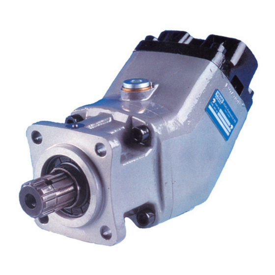
Parker F1 Series Service Manual
Truck hydraulics
Hide thumbs
Also See for F1 Series:
- Service manual (14 pages) ,
- Installation and start-up information (12 pages)

Related Manuals for Parker F1 Series


Summary of Contents for Parker F1 Series
- Page 1 Bulletin HY30-5502-M1/UK Service Manual Series F1 Effective: June, 2006 Supersedes: September, 1999...
- Page 2 HEREIN OR RELATED ITEMS CAN CAUSE DEATH, PERSONAL INJURY AND PROPERTY DAMAGE. This document and other information from Parker Hannifin Corporation, its subsidiaries and authorized distributors provide product and/or system options for further investigation by users having technical expertise. It is important that you analyze all aspects of your application, including consequences of any failure, and review the information concerning the product or sys- tem in the current product catalogue.
- Page 3 (5). A ring gear (6) connects the cylinder barrel to the drive shaft, causing these to rotate at the same speed. Parker Hannifin Pump and Motor Division Trollhättan, Sweden...
- Page 4 Pump fitted for right - hand rotation Turn the end cap half a revolution. Fasten the end cap. Torques to be used: F1-20, -30, -40, -60 60±10 Nm F1-80, -110 90±10 Nm Parker Hannifin Pump and Motor Division Trollhättan, Sweden...
- Page 5 48 - 4,8 = 43,2 l / min. If the flow drops An F1-40 running at 1225 r.p.m. gives - according to the below this limit, the pump is worn out and will have to be flowmeter. - a flow of 48 l/min. Parker Hannifin Pump and Motor Division Trollhättan, Sweden...
-
Page 6: Service Procedures
Fill out the space between retaining ring and shaft with heat - resistant grease. Fit the new outer seal ring. Parker Hannifin Pump and Motor Division Trollhättan, Sweden... - Page 7 Remove the pistons, which can be lifted out when held parallelly to the drive shaft. Remove barrel support. Loosen the screws joining the bearing housing and the barrel housing, and remove the barrel housing. Parker Hannifin Pump and Motor Division Trollhättan, Sweden...
- Page 8 - The end surface of the cylinder barrel. - The piston rings Scores and marks on these parts will always decrease the performance of the pump. Always replace them by new Parker Hannifin Pump and Motor Division Trollhättan, Sweden...
- Page 9 Find the marked tooth on the shaft. Place a gasket on the barrel housing. Parker Hannifin Pump and Motor Division Trollhättan, Sweden...
- Page 10 The number of gaskets between end cap and bearing housing determines the backlash. When assembling, use the same number of gaskets as found at the disassembly. If the number is unknown, try with 2 gaskets. Parker Hannifin Pump and Motor Division Trollhättan, Sweden...
- Page 11 Grooved Rivet Shaft Cylinder Barrel Barrel Support Piston Assy Piston Ring Guide pin Ring Gear Tap Rol Bearing Retaining Ring Needle Bearing Inner Ring not all sizes Barrel Housing Hex Socket scr. Parker Hannifin Pump and Motor Division Trollhättan, Sweden...
- Page 12 Parker Hannifin Pump and Motor Division Flygmotorvägen 2 SE-461 82 Trollhättan Sweden Tel: +46 (0)520 40 45 00 Fax: +46 (0)520 371 05 www.parker.com...
Need help?
Do you have a question about the F1 Series and is the answer not in the manual?
Questions and answers