Advertisement
UNRIVALLED
PERFORMANCE
in Heat Recovery Ventilation
Installation, maintenance & user manual
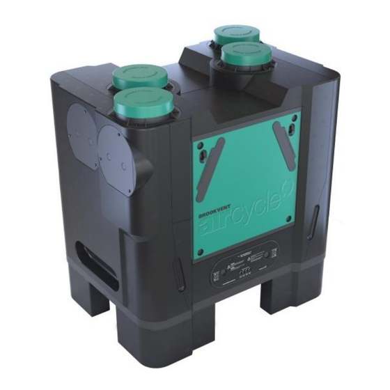
Applicable to the following aircycle 3.1 models:
PRODUCT CODE
AS 90-0301-WIN-01
AS 90-0301-WINS-01
DESCRIPTION
aircycle 3.1 c/w Integral Humidistat - Wall or Floor Mount
aircycle 3.1 c/w Integral Humidistat & Summer Bypass - Wall or Floor Mount
V. 3.1-300317
brookvent.co.uk
Advertisement
Table of Contents

Subscribe to Our Youtube Channel
Summary of Contents for BrookVent Aircycle 3.1
- Page 1 Applicable to the following aircycle 3.1 models: PRODUCT CODE DESCRIPTION AS 90-0301-WIN-01 aircycle 3.1 c/w Integral Humidistat - Wall or Floor Mount AS 90-0301-WINS-01 aircycle 3.1 c/w Integral Humidistat & Summer Bypass - Wall or Floor Mount V. 3.1-300317 brookvent.co.uk...
-
Page 2: Table Of Contents
Safety ............................3 Specifications/ Dimensions (mm) ....................5 Installation ..........................10 Electrical Connections/ Wiring ....................19 Controls and Settings ........................ 21 Maintenance ..........................26 User Operation .......................... 32 Trouble Shooting ........................34 10.0 Customer Support ........................35 V. 3.1-300317 brookvent.co.uk... -
Page 3: Introduction
‘habitable rooms’ such as bedrooms, dining rooms and living rooms. Model Variations This installation manual refers to the Brookvent aircycle 3.1 and pertains to the following models: PRODUCT CODE... -
Page 4: Safety
4 years covering parts only. In the instance of a defect, Brookvent may repair the product, replace the product free of charge or refund the cost of the product at Brookvent’s own discretion. In terms of installation, operation and maintenance please follow all instructions provided. - Page 5 In new build properties it may be prudent to check/ change your filters after the first 3 months of occupancy depending on the amount of residual ‘building dust’ present within the property. Failure to do so will affect your warranty. Filters can be purchased directly online from brookvent.co.uk V. 3.1-300317 brookvent.co.uk...
-
Page 6: Specifications/ Dimensions (Mm)
Specifications/ Dimensions (mm) FRONT SIDE V. 3.1-300317 brookvent.co.uk... - Page 7 Duct Connections V. 3.1-300317 brookvent.co.uk...
- Page 8 • Tempering summer bypass (Automatic variation between 20 - 27 Degrees Celsius. Optional Installation: Wall or Floor Mount Standards: Fully complies with Building Regulations for UK & Ireland SAP Appendix Q Listed | Energy Savings Trust Best Practice | CE Guarantee Period: 5 Years V. 3.1-300317 brookvent.co.uk...
- Page 9 Kitchen + 3 Wet 0.51 Room Kitchen + 4 Wet 0.64 Room Kitchen + 5 Wet 0.78 Room Kitchen + 6 Wet 0.98 Room Kitchen + 7 Wet 1.20 Room SAP 2012 (See SAP - PCDB for further details) http://www.ncm-pcdb.org.uk/sap/ V. 3.1-300317 brookvent.co.uk...
- Page 10 Inlet 44.4 53.7 55.3 54.9 46.9 38.8 28.4 26.7 59.9 54.2 39.7 Extract *Case radiated sound at 3m is calculated based on Hemi-spherical propagation. **Inlet and Extract sound at 3m is calculated based on uniform line source. V. 3.1-300317 brookvent.co.uk...
-
Page 11: Installation
Mounting The aircycle 3.1 is designed to be either wall or floor mounted. Please ensure that this method of fixing is suitable for the mounting surface and that it can safely bear the load. - Page 12 The unit can then be set onto the mounting surface with the lip of each bracket intersecting as shown in Fig. 3. Ensure the system is level when fully mounted. Fig. 1 Fig. 2 Fig. 3 V. 3.1-300317 brookvent.co.uk...
- Page 13 The unit should be mounted on the Floor, on a stable, level surface. Ensure the condensate connection at the bottom of the unit can be fitted to allow a minimum 5 degree fall to the internal drainage point. Waterless Dry Trap (Not Incl.) V. 3.1-300317 brookvent.co.uk...
- Page 14 (maximum length: 300mm) and kept taut as per the Domestic Compliance Guide (Part F: Eng and Wales 201 The spigots on the Brookvent aircycle 3.1 systems are suitable for connection to 150mm diameter round pipe. The label on top of the unit clearly identifies which spigot should be connected to which ducting route within the dwelling.
- Page 15 Air valves should be locked upon commissioning so that they are tamper proof. Duct designs/ layouts should always be adhered to if provided. The Domestic Compliance Guide: Eng. and Wales 2010 or relevant equivalent dependent upon local guidelines, should be adhered to in terms of installation practices. V. 3.1-300317 brookvent.co.uk...
- Page 16 MVHR systems generate considerable amounts of moisture due to their high Heat Recovery Efficiency; this moisture must be drained from the system to a suitable discharge location. The aircycle 3.1 is supplied complete with a centralised drainage connection on the bottom of the unit. Waterless Dry Trap (Not Incl.)
- Page 17 4.4 Inverting the unit The aircycle 3.1 can be inverted, changing the external duct connections from the right to the left of the system as required for specific property types, where required. A: Filter Cassette Standard Front Inverted Front B: PCB Module...
- Page 18 Step 11. On the face of the unit marked STANDARD; pull the mains cable through the unit and feed it through the blank control panel (F). Step 12. Secure the blank control panel using the M10 screws (D) and washers (C). V. 3.1-300317 brookvent.co.uk...
- Page 19 (it should be a snug fit). Step 7. Screw the top plug in place. Step 8. The unit can be connected from the side with 1 to all 4 connections. V. 3.1-300317 brookvent.co.uk...
-
Page 20: Electrical Connections/ Wiring
HRV Unit. Connecting to mains: The aircycle 3.1 unit comes pre-wired with 2m length of 4-core cable, which should be connected into a fan-isolation switch. In turn a 3-core mains cable should be used to connect to a 5A fused spur, which should be located close to the unit. The unit should never be connected to a plug outlet. - Page 21 5.1 Wiring Schematic 5.2 Colour code for internal wiring connectors V. 3.1-300317 brookvent.co.uk...
-
Page 22: Controls And Settings
Grey switch wire is triggered by a 230v boost signal such as a Wall Switch or Passive Infrared (PIR) Sensor. If the Boost for either fan is required to be set, it should always be set higher than the Trickle. Turning these speed pots clockwise increases the fan speed. V. 3.1-300317 brookvent.co.uk... - Page 23 Building Regulations (Part F: Means of Ventilation, England and Wales) or relevant equivalent dependent upon local guidelines. If further guidance is required on the commissioning process, please contact Brookvent directly. Example Commissioning (Based on Part F: Means of Ventilation, England and Wales) Property –...
- Page 24 The factory setting for humidity is 70% RH. Turning this Speed Pot clockwise increases the humidity level at which the unit will boost. NB. Upon start-up/ power-on the humidity sensor will be inactive for a period of 60mins due to calibration. V. 3.1-300317 brookvent.co.uk...
- Page 25 6.4 Boost Over-Run Timer All Brookvent aircycle systems come complete with an automatic boost over-run timer of 15mins (factory set). The grey ‘switch wire’ on the aircycle 3.1 systems (See section ‘5.0 Electrical Connections/ Wiring’) is used to boost the system.
- Page 26 6.6 Tempering Summer Bypass Feature available on selected models only (AS 90-0301-WINS-01). The Tempering Summer Bypass feature, unique to Brookvent aircycle systems, functions via thermostatically responsive solenoid which operates on a linear scale between 20 Degrees Celsius (No Summer Bypass) and 27 Degrees Celsius (Full Summer Bypass);...
-
Page 27: Maintenance
It is recommended that the filters are checked every 6 months. Replacement filters can be purchased online at brookvent.co.uk To change the filters, simply remove each filter cover cassette from the front of the unit and replace ensuring a press tight seal. - Page 28 Heat Exchange Core Check The aircycle 3.1 heat recovery core is protected by 2 no. filters. As long as the filters are regularly changed as detailed in the previous section there should be no need to access the system’s heat recovery core. However, should regular filter changes not be adhered to it may be advisable to access the system’s heat recovery core, and where required,...
- Page 29 Fan Replacement The aircycle 3.1 heat recovery system has a very straight forward fan replacement process should the unlikely event of a fan failure occur. Fan c/w scroll cassette Step 1. Isolate the unit from the mains and ensure all supply circuits are disconnected.
-
Page 30: Sensor Replacement
Sensor Replacement Replacement of the aircycle 3.1’s temperature sensor and/or humidity sensor is also very straight forward in the unlikely event of a failure occurring. 7.4.1 Temperature Sensor Replacement Temperature Sensor (Located on the “Fresh from outside” side of the unit... - Page 31 Step 8. Reinsert both filters (change if necessary) and replace the front door ensuring all four screws are securely fastened. Also ensure the filter tabs on the front of the unit are securely fitted. Step 8. Power the unit on at the isolator and ensure any supply circuits are reconnected. V. 3.1-300317 brookvent.co.uk...
- Page 32 PCB Module Replacement In the unlikely event of an electronic PCB failure, the Aircycle 3.1’s PCB module can be easily disconnected and replaced. PCB Module Step 1. Isolate the unit from the mains and ensure all supply circuits are disconnected.
-
Page 33: User Operation
▪ become loose over time and are kept sufficiently tight. User Operation The Brookvent aircycle 3.1 is an extremely compact and highly efficient Mechanical Heat Recovery Ventilation (HRV/MHRV) system, specifically designed for medium to large dwellings and apartments. The system should be run continuously 24 hours a day, and should only be disconnected by a competent person during service or maintenance. - Page 34 These sensors detect humidity in the air and trigger the system into boost mode when humidity reaches a certain level. These are typically placed in bathrooms or in kitchens. Please note that the aircycle 3.1 system has an In-built humidistat that operates in the same fashion.
-
Page 35: Trouble Shooting
(Please note that the aircycle 3.1 system has an adjustable boost overrun time of up to 15mins). *The items detailed above are examples of the types of Manual Control Options that are typically used in conjunction with the Brookvent aircycle 3.1 *... -
Page 36: Customer Support
10.0 Customer Support At Brookvent we pride ourselves on providing Gold Standard after sales and support to all customers. Please feel free to contact one of our specialist team about any query you may have and we will be more than happy to assist you.
Need help?
Do you have a question about the Aircycle 3.1 and is the answer not in the manual?
Questions and answers