
Related Manuals for Marenius MM-4240

Summary of Contents for Marenius MM-4240
- Page 1 MM-4240 4 channel stereo mixer 6 channel recorder | Manual | FW 2.1.1 Version 2.00 4/4/2014...
-
Page 2: Table Of Contents
9.4.4 Time code auto record 9.5. G ENERAL SETUP 9.5.1 File size 9.5.2 Device info 9.5.3 Set time and date 9.5.4 Color settings 9.5.5 Misc. settings 10. MIXING WITH THE MM-4240 10.1. P HANTOM POWER 10.2. P GAIN 10.3. C HANNEL FADER 10.4. L IMITERS 10.4.1. - Page 3 14.3. H EADPHONE OUTPUT BLOCK DIAGRAM 14.4. M ONITOR OUTPUT BLOCK DIAGRAM 15. TECHNICAL SPECIFICATIONS APPENDIX A. FIRMWARE UPDATE Package includes MM-4240 Mixer / Recorder Mains AC/DC adapter Mains cable Interface cable for D1/D2 outputs ...
-
Page 4: General Description
1. General description The MM-4240 is a 4 channel stereo mixer and a 6 channel recorder in a very compact format. The unit has 4 high quality, digitally controlled, THAT Corporation microphone pre-amps. There are 5 stereo output busses, 1 master, 1 monitor, 2 digital and 1 headphone output. The output busses can be individually assigned to any input pair or the master mix bus. -
Page 5: Front Panel
The master fader affects the mix-bus. Headphone jack The headphone jack accepts headphones with an impedance of 32-600Ω. Note: high volume can cause damage to your ears; always turn the headphone volume down before inserting the headphones plug. 4/4/2014 MM-4240 User Manual v.2.00... - Page 6 Move the button to the right to fast forward. RIGHT If the MM-4240 is in recording or idle mode a virtual time code slate can be displayed on the screen using the RIGHT button. Previous track / Fast reverse (only used in play mode) LEFT Move the button to the left to fast reverse.
- Page 7 Left and right pan for each channel Pre-gain (one for each channel) (inner potentiometer) Digitally controlled analog gain control. The gain can be set in 6dB steps, 0-60dB. Pre-gain CLIP The CLIP LED is illuminated if the pre-gain stage is clipping. 4/4/2014 MM-4240 User Manual v.2.00...
-
Page 8: Back Panel
Four input channels for microphone or line level input. Digital output busses (2 stereo pairs) (mini-DIN 4 connector) Two standard S/PDIF output streams. The MM-4240 is shipped with a mini-DIN to 2xBNC converter cable. The output voltage is set accordingly to the AES3-ID standard, if the output is connected to an AES3 digital input a voltage level converter may be needed. - Page 9 The monitor output may be padded -20dB for connection to low level inputs of e.g. cameras. Remote control The remote control input can be used to connect an external record switch. When the switch is closed the MM-4240 is recording until the switch is opened. 4/4/2014 MM-4240 User Manual v.2.00...
-
Page 10: Balanced Xlr Female / 1/4" Trs Pin Assignment
Pin 3 3.3. 1/4” TRS stereo pin assignment Unbalanced analog audio input/output Connector type Ground Sleeve Left Right Ring 3.4. Mini-DIN 4 pin assignment Digital audio output Connector type Mini-DIN 4 BUS1- BUS2- BUS1+ BUS2+ 4/4/2014 MM-4240 User Manual v.2.00... -
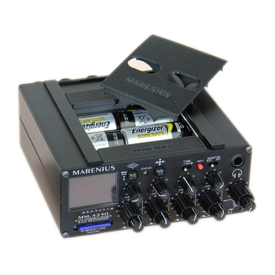
Page 11: Powering The Mm-4240
The MM-4240 can be powered from an external power supply of 6V-15V; the external power supply can be a mains adapter, batteries or any power supply that is able to delivery at least 2A of current. Even if the MM-4240 doesn’t draw 2A the power supply must be able to handle load transients. - Page 12 “SIDE”, MS matrix enable, side channel Record/test tone field If the MM-4240 is recording a “REC” symbol is lit in the field. If the test tone is enabled a “1kHz” symbol is flashing in the field. Time code display area The time code display area can show time code with three or four numbers.
-
Page 13: Quick Routing Information
To manually exit the feature press the right button again. When filming the MM-4240 the LED will flash with one FPS + 1 millisecond if external time code is connected. If external time code is not present on the time code input connector the LED will flash with 24FPS. -
Page 14: Main Menu
The main menu structure is shown in the illustration below. The menu will automatically return one step every 15 second until the general screen has been reached. A quick exit from the menu can be done using the “INFO” button. 4/4/2014 MM-4240 User Manual v.2.00... -
Page 15: Input Configuration
9.1.1 Limiters The MM-4240 is fitted with four ultra-low THD opto-limiters. To enable a limiter on a channel press the center button, then an “X” is displayed for the selected channel. The limiters are only connected to the channel faders. -
Page 16: Analog Multiplexing And Nominal Analog Level
Channel 1 and channel 2 input (After pre-gain and channel fader) (input bus) 5. 3+4 Channel 3 and channel 4 input (After pre-gain and channel fader) (input bus) All digital output busses can be coupled to any of the input busses through the table shown above. 4/4/2014 MM-4240 User Manual v.2.00... -
Page 17: Record Configuration
9.4.4 Time code auto record The MM-4240 is able to start and stop recording depending on a time code signal. If the feature is turned off the device will function as a regular recorder. This option has two choices, time code detection (DET) and time code running (RUN). -
Page 18: General Setup
The MM-4240 will split files sample-accurate, so files joined together in post-production will be seamless. However if the SD card is to slow this will fail since the internal buffer will overflow. To avoid overflow the file size may be decreased. This requires some trial and error on the used SD card to find the limits. -
Page 19: Misc. Settings
In that case the time code will be one frame late. The “Misc” menu also includes a firmware update option, for information about the firmware update procedure see appendix “Appendix A. Firmware update”. 4/4/2014 MM-4240 User Manual v.2.00... -
Page 20: Mixing With The Mm-4240
10. Mixing with the MM-4240 Mixing audio with the MM-4240 is very straight forward, however there are some details that require attention to avoid clipping and produce mixes with high quality sound. 10.1. Phantom power The phantom power can be enabled for each input channel if needed. The phantom power shall not be enabled unless required since it will draw excessive power and add a small amount of noise to the signal. -
Page 21: Limiters
10.7. Mixing The mixing stage of the MM-4240 is a classic summing mixer. Since all input signals are added together the mix may be clipped. The user must be aware of the fact that two identical input signals summed together will result in a 6dB higher output signal. If the mix is clipped this is shown as a “CLP”... -
Page 22: Monitoring
10.9. Monitoring The MM-4240 has a monitor input which can be routed directly to the headphone for fast checking of external equipment. The MM-4240 has a dedicated switch on the front panel for switching between internal audio and monitor audio. -
Page 23: Recording With The Mm-4240
If the buffer size isn’t exceeded during this time the MM-4240 will be able to split the files sample correct. Sample correct recordings can easily be merged during the post- production phase. -
Page 24: Recording
LED will turn red and a “REC” symbol is shown in the display. The LED will turn on after the “REC” symbol (max 1 sec) since the MM-4240 is synchronized to the internal or external time code clock. The samples are saved when the LED is lit. When recording the time code will freeze and fade away and elapsed recording time will be shown instead. - Page 25 12. Playback tracks The MM-4240 has an internal playback feature allowing the user to play recorded files. The MM-4240 output two selectable tracks on all output busses. To change between tracks use the up and down key of the menu navigation key. If the “PLAY ATT” is enabled the user may use the master fader as a volume control.
- Page 26 Track number and track meter The MM-4240 always shows six tracks even if the recording only has two or four tracks. The highlighted tracks are the tracks that currently are presented on the output busses. To switch between outgoing tracks the up and down switch of the menu navigation key is used.
- Page 27 BNC connector on the back of the unit. If a time code signal is present the MM-4240 will show the incoming time code in the display. If the time code is removed the device will be showing an “S” after the time code.
-
Page 28: Block Diagrams
MARENIUS ELEKTRONIKUTVECKLING AB | www.marenius.se www.marenius.com www.audiodesign.pro 14. Block diagrams 14.1. Channel input block diagram 14.2. Master output block diagram 14.3. Headphone output block diagram 14.4. Monitor output block diagram 4/4/2014 MM-4240 User Manual v.2.00... -
Page 29: Technical Specifications
Output level (Into 75Ω) ................1V p-p Output sampling rate ................... 96 kHz Output resolution ..................24 bit Dimensions and weight Size (H x W x D) ..................5.6 x 14 x 13.8 cm Weight, excl. batteries ................. 900 grams 4/4/2014 MM-4240 User Manual v.2.00... - Page 30 6. Go to firmware update in the menu and select firmware update. 7. The update will take 2-3 minutes. 8. After the internal DSP has been updated the MM-4240 will reboot and update the internal controller. When the controller is updating the BLUE led will flash with different frequencies.
Need help?
Do you have a question about the MM-4240 and is the answer not in the manual?
Questions and answers