Table of Contents
Advertisement
Quick Links
Peter Sinkiwskij
-04'00'
Date: 2017.08.03 11:56:46
m, c=US
email=peter@pneumercator.co
ou=Headquarters,
o=Pneumercator Co., Inc.,
DN: cn=Peter Sinkiwskij,
Sinkiwskij
Digitally signed by Peter
ETD1000 REMOTE ELECTRONIC TANK DISPLAY
TMS SERIES TANK MANAGEMENT SYSTEMS
This document describes the installation, programming and operation of the ETD1000 Remote
Electronic Tank Display, which is designed for use with any TMS2000, TMS3000, or TMS4000 Tank
Management System.
INSTRUCTION MANUAL
FOR
DWG NO. 20035 REV. A
Advertisement
Table of Contents

Summary of Contents for Pneumercator ETD1000
-
Page 1: Instruction Manual
ETD1000 REMOTE ELECTRONIC TANK DISPLAY TMS SERIES TANK MANAGEMENT SYSTEMS DWG NO. 20035 REV. A This document describes the installation, programming and operation of the ETD1000 Remote Electronic Tank Display, which is designed for use with any TMS2000, TMS3000, or TMS4000 Tank Management System. -
Page 3: Table Of Contents
Communications ....................14 2.2.2.1 Cable Requirements .................... 14 2.2.2.2 ETD1000 Terminal Connections ................. 15 2.2.2.3 ETD1000 Communications Wiring Detail ............15 2.2.2.4 TMS Communications Wiring Detail ..............15 2.2.2.5 Line Termination Resistor ................... 16 2.2.2.6 TX1064-1 Wiring Detail ..................17 Section 3.0... -
Page 5: Product Overview
1.0 Product Overview The ETD1000 Electronic Tank Display panel is used in applications where it is desired to view TMS series tank management data from various on-site locations at distances up to 4000 feet (1200M) away from the main console. Since the ETD1000 is a microprocessor-based, addressable device communicating over the TMS RS-485 Peripheral Expansion Bus, up to 16 ETD1000 panels may be connected to a single TMS. -
Page 6: Tms Compatibility
DWG NO. 20031 REV. A Figure 1.0-2 Interior View 1.1 TMS Compatibility The ETD1000 can be used with any TMS2000, TMS3000, or TMS4000 provided appropriate firmware is loaded. ETD1000 support is provided with the following TMS console firmware versions; Vxx.99.90 thru Vxx.99.99 Vxx.00.xx Vxx.01.xx Vxx.02.xx... -
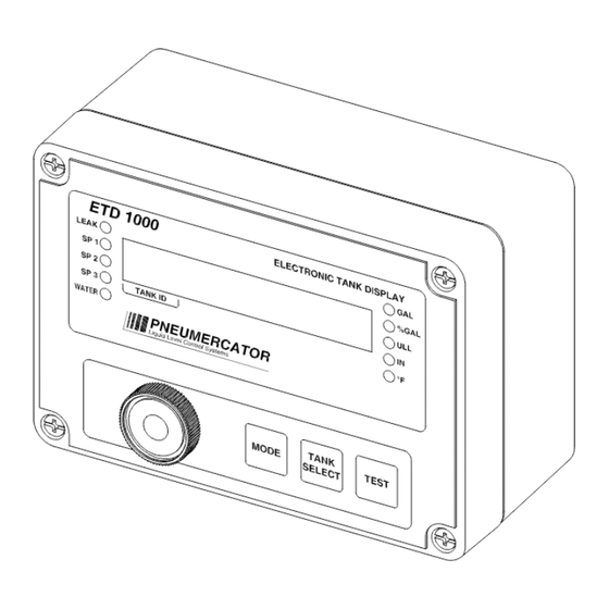
Page 7: Display Data
= Tank ID The “tank name” message is displayed when the MODE pushbutton is momentarily activated, as described in Section 4.0 ETD1000 Front Panel Operation 1.4 Alarm LEDs Alarm LEDs are provided to annunciate tank-related alarms as follows;... -
Page 8: Audible Annunciator
Under alarm conditions, the beep rate of the annunciator varies with the alarm type as follows; Alarm Beep Rate Leak Fast (50ms) Medium Fast (100ms) Medium Slow (200ms) Slow (400ms) Water Slow (400ms) ms = milliseconds ETD1000 Instruction Manual - 2017-07-01.docx Page 8 of 28 July 1, 2017... -
Page 9: Installation
2.0 Installation The ETD1000 is designed for both indoor and outdoor installation. If the unit is to be installed outdoors, the installer must pay attention to local code requirements for outdoor conduit runs containing AC line voltage. WARNING! This device is designed for Ordinary Location, Non-Hazardous installation only, as defined by Underwriters Laboratories (UL) and the National Electrical Code (NEC). - Page 10 ETD1000 Instruction Manual - 2017-07-01.docx Page 10 of 28 July 1, 2017...
- Page 11 DIMENSIONS: INCHES (MM) 32 [180.0] USE (4) #10 X 2 " LENGTH MOUNTING SCREWS (3/8" MAX. SCREW HEAD DIA.) 3 21 [93.0] DRAWING NO. 20024 REV. N/C...
- Page 12 ETD1000 Instruction Manual - 2017-07-01.docx Page 12 of 28 July 1, 2017...
-
Page 13: Wiring
Note that the AC terminal block can be wired in-place or unplugged. 115/230 VAC SWITCHABLE 1/2 AMP 250 VAC FAST 115V ACTING FUSE NEUTRAL 115/230 VAC 50/60Hz DWG NO. 20026 REV. A Figure 2.2.1-1 ETD1000 Instruction Manual - 2017-07-01.docx Page 13 of 28 July 1, 2017... -
Page 14: Communications
2.2.2 Communications The ETD1000 supports an RS-485 multi-drop cabling topology as illustrated in Figure 2.2.2-1 below. Maximum cable distance from the TMS console to the furthest ETD1000 is 4000 feet (1200M). END-OF-RUN ETD1000 OR RA400 ETD1000 OR RA400 ETD1000 OR RA400... -
Page 15: Etd1000 Terminal Connections
Previous versions have a 6-pin modular jack, as illustrated in Figure 2.2.2.4-2 below. If the board type is a previous version and was indicated on the order to the factory, the ETD1000 is shipped with a modular-jack-to-terminal-connector adapter, also shown in Figure 2.2.2.4-2. -
Page 16: Line Termination Resistor
The RS-485 bus requires that the end-of-run device be terminated with a 120-ohm resistor. This is accomplished by setting the LINE TERMINATION switch to “ON” if the selected ETD1000 is the last device on the bus. Otherwise this switch should be set to “OFF”. -
Page 17: Tx1064-1 Wiring Detail
1. THE 115/230 VAC SWITCH MUST BE SET TO 115V FOR 115 VAC OPERATION OR 230V FOR 230 VAC OPERATION. IA2-3 CLOSED 2. THIS NOTE APPLIES TO ETD1000 INTERFACE WITH TX1064-1 ONLY: FOR PROPER OPERATION, THE TX1064-1 UNIT SPARE CLOSED MUST BE POWERED UP EITHER PRIOR TO OR SIMULTANEOUSLY WITH THE ETD. - Page 18 ETD1000 Instruction Manual - 2017-07-01.docx Page 18 of 28 July 1, 2017...
-
Page 19: Configuration
3.1 On-Board Programming 3.1.1 Setting Logical Address – S3 The TMS series console has the ability to individually address up to sixteen (16) ETD1000 remote displays. Rotary dipswitch S3 is used to select unique addresses for each ETD1000 connected to the same TMS. -
Page 20: Dipswitch Settings - S4
Front Panel (FP) Acknowledge Settings: If set to LOCAL, front panel acknowledgement will only silence local ETD1000 audible alarm. If set to LOCAL and TMS, both ETD1000 and TMS audible alarms will be silenced. -
Page 21: Front Panel Programming
The ETD1000 is shipped from the factory with all available tanks, alarms and display modes enabled. Note that tanks that are not enabled on the TMS are automatically disabled on the ETD1000 and therefore do not require any programming to disable them. -
Page 22: Programming Procedure
Hold TANK SELEC T until one beep Closed shapes indicate names of Menus while open brackets indicate ETD Navigation Flowchart ETD1000 Firmware V20.06 names ofValues. ETD1000W Firmware V10.14 ETD1000 Instruction Manual - 2017-07-01.docx Page 22 of 28 July 1, 2017... - Page 23 SP2 Alarm Enable *YES/NO SP3 Alarm Enable *YES/NO Water Alarm Enable *YES/NO Normally *OFF/ON Relay Timer *NONE/1-9 MINUTES Relay # Alarm LEAK/SP1/*SP2/SP3/WATER Relay # Tank *NO/1-12 *Factory Default ETD1000 Instruction Manual - 2017-07-01.docx Page 23 of 28 July 1, 2017...
- Page 24 ETD1000 Instruction Manual - 2017-07-01.docx Page 24 of 28 July 1, 2017...
-
Page 25: Front Panel Operation - Operator Mode
LED is on continuously, it applies to the currently displayed tank. Note that this alarm may apply to more than one tank, which can be determined by viewing each tank with the TANK SELECT button. ** Factory defaults shown. Other values and may be programmed. ETD1000 Instruction Manual - 2017-07-01.docx Page 25 of 28 July 1, 2017... - Page 26 ETD1000 Instruction Manual - 2017-07-01.docx Page 26 of 28 July 1, 2017...
-
Page 27: Product Specifications
Maximum Cable Length: 4000 Feet/1200 Meters total to end of run Slave Address Select: 1 thru 16, Rotary Dip Switch Selectable Display Update Rate from TMS: 400 to 600 milliseconds (0.4 to 0.6 seconds) ETD1000 Instruction Manual - 2017-07-01.docx Page 27 of 28 July 1, 2017...
Need help?
Do you have a question about the ETD1000 and is the answer not in the manual?
Questions and answers