Table of Contents
Advertisement
M910s
User Guide and
Hardware Maintenance Manual
Machine Type (MT):
10MK, 10ML, 10QM
Energy Star MT:
10MK, 10ML, 10QM
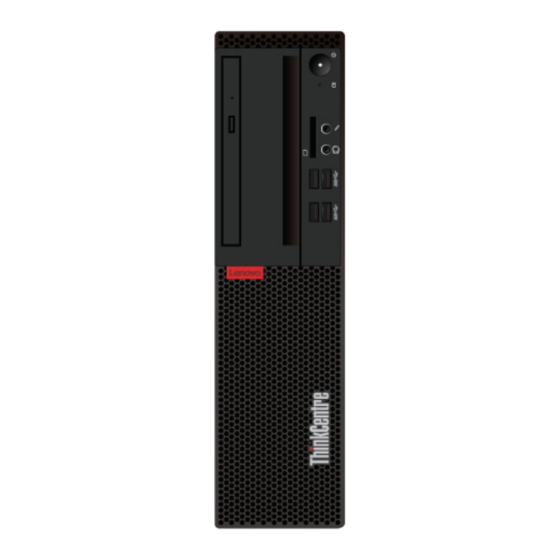
Overview
Locations of indicators,
connectors, and
controls provided on
your computer
Replaceable parts
Locations of the
replaceable parts on
your computer
Specifications
Specifications of your
computer
Replacing CRUs
Replacing instructions
for Customer
Replaceable Units
(CRUs)
Computer locks
Locking devices for
your computer
Replacing FRUs
Replacing instructions
for Field Replaceable
Units (FRUs) (for
technicians only)
Advertisement
Table of Contents


Need help?
Do you have a question about the ThinkCentre M910s and is the answer not in the manual?
Questions and answers