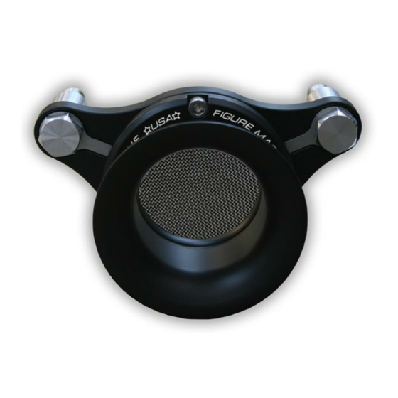
Summary of Contents for Figure Machine XLFLOW-STACK
- Page 1 Figure Machine 9208 Venture Ct – C9 Manassas Park VA 20111 Info@figuremachine.com www.FigureMachine.com Installation Manual XLFLOW-STACK...
- Page 2 XLFLOW-STACK EXPLODED VIEW ½” WASHER (2) ( FOR CARBURETED MODELS ONLY SPACER BOLT (2) GASKET (STOCK COMPONENT) BACKING PLATE (1) BOLT; ¼-20 X ½” SOCKET HEAD LOW (3) KEY WAY CHANNEL COVER (2) BREATHER BOLT (2) O-RING (1) COLLAR AND VELOCITY STACK (1)
- Page 3 Dear Customer, Thank you for purchasing Figure’s XLFLOW-STACK Air Cleaner Assembly. This Air Cleaner has been engineered to enhance the performance and appearance for the life of your bike. Proper installation is essential to your overall satisfaction, so please read these instructions before attempting to install.
- Page 4 XLFLOW-STACK Installation 1) Remove Stock Filter Assembly 1.1) Remove the two 3/16 Allen Cap screws that secure the Filter Cover and Plate. 1.2) Remove the three T25 Torx screws that secure the stock filter. Remove the gasket from the stock filter and set aside for later use.
- Page 5 1.3) Remove the stock breather bolts and throttle body bolts. On some models there will be vent lines being fed to the air filter assembly, remove these and re-route them to beneath the engine. Remove the stock breather box. 1.4) Remove throttle body support (fuel injected models) by removing the bolt in the center.
- Page 6 2) PREPARE XLFLOW-STACK BACK PLATE 2.1) Install the breather spacer bolts to the engine heads (using Loctite). On carbureted models use install ½” washers between the bolts and the heads. 2.2) Insert three ¼”-20 x ½” LOW head bolts through the backing plate and then through the stock gasket (use Loctite on the bolts).
- Page 7 2.3) Insert the breather bolts through key hole, the backing plate, and then finger tighten to the breather spacer bolts (use Loctite on the breather bolts). 2.4) After all bolts from steps 2.1 through 2.3 have been loosely attached, fully tighten the 3 intake bolts and then fully tighten the breather bolts.
- Page 8 7/16” bolts through the collar and into the backing plate (use Loctite on the bolts). 2.6) Gradually tighten each bolt such that the collar is evenly drawn against the backing plate until all bolts are fully tight and the collar is flat against the backing plate.

Need help?
Do you have a question about the XLFLOW-STACK and is the answer not in the manual?
Questions and answers