Table of Contents
Advertisement
Advertisement
Table of Contents

Subscribe to Our Youtube Channel
Summary of Contents for Master MST-3000
- Page 1 MST-3000 Motorcycle Diagnostic Instruction ZEUS TECH CO.LTD, SHEN ZHEN, CHINA...
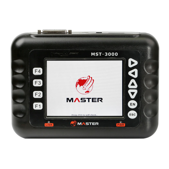
- Page 2 Part 1 Scanner Introduction & Attentions Scanner appearance and keys: 5.6’color LCD Keypad Signal Light Power light Top view: USB to RS232 interface Diag. interface socket SD card socket 12V power supply socket ZEUS TECH CO.LTD, SHEN ZHEN, CHINA...
- Page 3 Diag. accessories: ZEUS TECH CO.LTD, SHEN ZHEN, CHINA...
- Page 4 ZEUS TECH CO.LTD, SHEN ZHEN, CHINA...
- Page 5 ※Please connect the power cable to the scanner’s 12V socket when diagnosis with YAMAHA models. ※Please connect the power cable to the scanner’s 12V socket when diagnosis with HONDA models. Buttons descriptions ▲▼ Up down Arrow Keys:Choose items ◄ ►Left right arrow keys:Shift pages Enter:Perform Esc:Return F1,F2,F3,F4 Function keys:Reserved...
- Page 6 Attentions Use restrictions 1. The displays screen and illustrations (such as key markings) in this manual are for illustrative purpose only, and may differ somewhat from the actual items they represent. 2. The contents of this manual are subject to change without notice. 3.
- Page 7 Part 2 Connection Specifications 1、Scanner accessories Testing accessories Scanner Main test cable 3pin diagnostic adaptor Connection methods: 1.Connect the main test cable 2.Connect the diagnostic cable 3.Connect to the car diagnostic cable ZEUS TECH CO.LTD, SHEN ZHEN, CHINA...
- Page 8 Part 3 Operation Descriptions (Take Kawasaki ZR1000 as sample) 1. Connection Connect Scanner to motorcycle by following the steps of Part 2. 2. Perform function options Start the scanner, it will come out options as below System Setup Diagnosis View Version Time Perform:1.DIAGNOSIS:Enter maintenance diagnostic procedure.
- Page 9 Vehicle Selection Automatic ●Choose one way to enter at random Vehicle-mounted system ●If press <Enter> to enter Engine. If successful, will appear: Otherwise connection fail, it will appear: ZEUS TECH CO.LTD, SHEN ZHEN, CHINA...
- Page 10 indicate that failure to connect 01. ECU Data. Enter this option will display the information of ECU, as below: 02.Current Data Current Data is the numeric figures of the working status for motor engine, through this data we can know whether motor works normally. Select Current Data to enter Current Data interface: Item name Current page and...
- Page 11 You can press [F1] key to show more information if the item name shows incompletely. Just as below in yellow: Press [F1] In the current page, you can press YES to enter waveform function, it is able to display numerical changes of the selected item. As below: Item name Current Shape...
- Page 12 Please press [F2] if you want to know the item introduction in details,but it just be supported in some items. 03.Freeze frame Data In the function list select Freeze frame Data displays: Freeze frame Data option: ●Press <Enter>: ZEUS TECH CO.LTD, SHEN ZHEN, CHINA...
- Page 13 04.Read fault Data In the function list select Read fault Data displays: Read Fault Code option: Fault description Fault code Current page and total pages 05.Erease Fault Code: In the function list select Erase Fault Code will display: Note! Before erase fault code please switch on the key and not to start engine. Press YES to erase fault code.
- Page 14 06.Actuators Test: In the function list select Erase Fault Code will display: ZEUS TECH CO.LTD, SHEN ZHEN, CHINA...
- Page 15 Part 4 System Settings And View Version Select menu SYSTEM SETUP , Press <Enter> to enter next menu, as below: 1. Basic setup This function can set whether the buzzer sound, and modify the current language. Press UP or DOWN to select item, Press LEFT or RIGHT to modify the option’s values. 2.
- Page 16 Press LEFT or RIGHT to select item, Press UP or DOWN to modify the option’s values. Select menu View Version , Press <Enter> to enter next menu, as below: Note: 1. The clock chip need to use button batteries (3.0 ~ 3.3 V) power supply, prevent clock data is lost when the power is cut off.
- Page 17 Part 5 Offline Upgrade 1. Extract the new package to a new folder; 2. Plug the SD card through the card reader to the PC and delete all files of the SD card; Sd card on the PC 3. Copy all the files to SD card from the folder which have the extracted files; 4.
- Page 18 press ESC to cancel. ※Note: The scanner use SD card format for FAT32, please pay attention to when formatting the SD card, otherwise the tool will not be able to work properly. ZEUS TECH CO.LTD, SHEN ZHEN, CHINA...
Need help?
Do you have a question about the MST-3000 and is the answer not in the manual?
Questions and answers