
Summary of Contents for Dynisco LMFI 5000
- Page 1 LMFI 5000 Series Melt Indexer User’s Guide Original English Version Manual Part No. M0726(2)
-
Page 2: M0726(2):Lmfi Series 5000 Lab Melt Flow Indexer
SUPPORT CONTACT INFORMATION Dynisco Polymer Test can be contacted for questions and support at: By Phone and Fax: Phone +1 508 541 9400 Fax +1 508 541 6206 To help us handle your questions as quickly as possible, have the following items ready before you call: 1. -
Page 3: M0726(2):Lmfi Series 5000 Lab Melt Flow Indexer
The information provided herein is believed to be true and correct but no warranty is given as to its completeness, accuracy or fitness for use for any particular purpose. Dynisco shall not be liable for any loss or damage arising from the failure to achieve a particular result by the application of any route, method or process that is recommended herein. -
Page 4: Table Of Contents
TABLE OF CONTENTS SAFETY INSTRUCTIONS ........................6 Warnings, Danger and Informational Symbols ................. 6 Safety summary ..........................7 Use Gloves, it's very HOT! ......................7 Electrical Hazard ........................... 8 Calibration Thermometers Using Mercury................. 8 Pinch Points ........................... 9 Fumes From Materials........................9 INTRODUCTION .......................... - Page 5 The Amount of Sample ....................... 28 Create/Edit Test Conditions ........................ 29 System Configuration ........................... 31 Selecting Multi-select Data ........................31 Entering Numeric Data ......................... 33 Setting Up a Test ..........................34 Loading and Packing Material into the Barrel ................... 35 Running a Test ............................
-
Page 6: Safety Instructions
SAFETY INSTRUCTIONS All safety instructions must be understood and observed. Non-observance of safety instructions may cause damage to life and health of persons, environmental damage and/or extensive damage to property. Observing the safety instructions included in the operating instructions will help to avoid dangers, to operate the product profitably and to secure the full use of the product. -
Page 7: Safety Summary
Safety summary The following are recommended safety precautions unrelated to any specific procedures in this manual and therefore do not appear elsewhere. Personnel must understand and apply them as appropriate during all phases of operation and maintenance. IN ALL CASES, BE PRUDENT. ... -
Page 8: Electrical Hazard
Your Dynisco Lab Melt Flow Indexer contains high voltage inside the housing. DO NOT remove the housing or any part of its outer covers; there are no user serviceable parts inside. Service should only be done by a qualified DYNISCO Service Technician. Be sure the outlet used to power the indexer is properly grounded. -
Page 9: Pinch Points
Pinch Points Do not place weights in precarious positions where they can be bumped and fall to the floor. For large test weights (over 10 kg) the pneumatic lift system is recommended. The lift system has a mechanical capture rod which will not allow the weights to “fall” out of the machine. When the machine is in operation the lift system moves the weight downward somewhat quickly creating an area where anything lying beneath could be crushed. - Page 10 • No modifications will be made to the component except by a Dynisco service person. • The necessary personal protective equipment for the operation, maintenance, and service will be available and used by any personnel performing these functions.
-
Page 11: Introduction
Dynisco Polymer Test Systems has found that charging a consistent mass of material into the barrel (±0.1 grams) is the most critical factor in getting precise data. -
Page 12: Specifications
SPECIFICATIONS UTILITIES: Electrical Requirements: 100-120 VAC / 220-230 VAC, 6A/4A-Peak at Power-up, 5A/2.5A, 500VA-normal operational power, 50 Hz / 60 Hz PNEUMATICS: Lift Option (PSI/Bar): MIN: 60/4.2 MAX: 80/5.5 Packer Option (PSI/Bar): MIN: 20/1.4 MAX: 50/3.5 DIMENSIONS: Base model With Lift System (no weights installed) Height (in/cm) 20/51... -
Page 13: Instrument Maintenance Recommendations
Pneumatic Lift maintenance: The guide rod and the pneumatic cylinder rod can be lubricated. Dynisco Polymer Test suggests that WD-40 or machining oil be used as a lubricant. You can also spray a small amount of WD-40 into the air manifold through the manifold’s air intake to lubricate all internal parts. -
Page 14: Equipment Setup
(total approx. 300lbs/136.36Kg). DYNISCO POLYMER TEST recommends placing from left to right, if using these options, the melt indexer; sample scale and computer. Shake test the melt indexer for stability. The bench top should also be able to withstand hot dies and tools being dropped on them. -
Page 15: Level The Melt Indexer
Level the Melt Indexer Using a small round bubble level, level the melt indexer. Place the level on top of the COLD barrel and using the adjustable screw feet, bring the machine into level. Tighten the locking nuts to keep the feet in level position Test shake the melt indexer for stability. -
Page 16: Instrument Overview
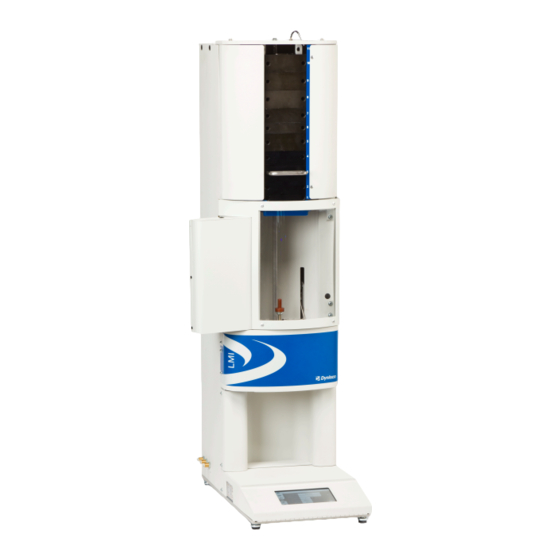
Instrument Overview Front View Lift System Packer Encoder Figure 1: LMFI with lift, encoder and packer Figure2: LMFI base unit Figure shows LMFI with the lift option; encoder option and packer option. Figure 2 shows the LMFI base unit that has no options Rear View Power Switch Power Cord... -
Page 17: Spares/Consumable Items
LMFI will show the model, power requirements and the instrument serial number. Spares/Consumable Items Item Part No. Qty (Each) LMFI 5000 Operator’s Manual M0726 Barrel (If wore, out of specification) 4051-25A Piston Assembly (Tip, Piston, Weight Top) 7051-72... -
Page 18: Instrument Operation/Log-In
Instrument Operation/Log-In When the system is powered-up, a log-in screen will appear. Below is a list of default user names and password and levels of access. The system has 5 levels of default user types. Admin and Maintenance user levels are defaulted with instruments at shipment. Users of Guest, Tester, and Manager levels will have to be added by the Admin level user if desired. -
Page 19: Instrument Operation/Icons
Instrument Operation/Icons – Icons An icon will be displayed when a device has been connected to either the master or host USB connections. Remote computer is connected Printer is connected Error during initialization of the remote computer Error during initialization of the printer Mass storage device is connected Scale is connected Error during initialization of the mass storage... -
Page 20: Instrument Operation/Menus
Instrument Operation/Menus – Menu Buttons Menu buttons are a specific type of button that does not have the same attributes as a normal button. The menu button can be: not selected, selected, or disabled. The button is only a touch area when in “not selected” mode. Action Not Selected Selected... -
Page 21: Instrument Operation/Buttons
Instrument Operation/Buttons Buttons – A button is an active touch area that will perform a specific action on the release of the button. There are three states to a button: released, pressed, and disabled along with the option of a press and hold which will repeat the desired action as long as the button is pressed. - Page 22 Buttons Continued Action Released Pressed Disabled Displays the test conditions Edit screen with the currently selected test conditions. Stops the currently running test or stops the series if the system is running a series. Displays the lift override/ manual operation window. Creates new test conditions and changes to the test conditions Edit screen.
- Page 23 Buttons Continued Action Released Pressed Disabled Selects the current test conditions and displays the test setup screen. Displays the edit date and time screen. Starts a test with the current test information and displays the test status screen. Sets the system volume to the the maximum level.
-
Page 24: Instrument Operation/Miscellaneous Touch Areas
Instrument Operation/Miscellaneous Touch Areas Miscellaneous Touch Areas— The following items are touch areas that will perform the specified operation after the button has been released. There are three states to a button: released, pressed, and disabled. Action Released Pressed Disabled Displays the multi-selection screen with the current value selected. -
Page 25: Test Calculations
Method B flow rate must equal Method A. This apparent melt density definition forces the two test methods to agree. DYNISCO POLYMER TEST recommends taking an average of apparent melt densities from at least five separate A/B tests on representative samples of polymer. -
Page 26: Calculations: Method B
The encoder senses distance travelled by following the bottom of the test weight(s) which are at the top of the piston. With all Dynisco Polymer Test Systems flags, Method A and B start in the same place. Flags may be any length desired and a test can have any number as long as the total distance of flags is not longer than the distance from the start point and where the piston would land on the top of the die (≈25.4mm). -
Page 27: Calculating Pet Intrinsic Viscosity (I.v.) From The Melt Indexer
Intrinsic Viscosity are related in such a way that IV can be directly calculated from Melt Index values. This is described in greater detail in the applications brief, "Correlating Melt Rheology of PET to Solution Intrinsic Viscosity" by J. Reilly and P. Limbach, available from DYNISCO POLYMER TEST on request Melt Flow vs. -
Page 28: The Amount Of Sample
The Amount of Sample ASTM gives a recommendation of how much material to put in the barrel to perform a test. However, by determining the proper charge and controlling it from run to run. Testing can be made easier and more reproducible. The distance from the top of the die to the piston’s first scribe mark is about 5 cm. -
Page 29: Create/Edit Test Conditions
Create/Edit Test Conditions Create/Edit Test Conditions Cont Pressing the new button will display the edit test conditions screen with a default set of test conditions. Select the desired test conditions to edit. Pressing the edit button will display the edit test conditions screen with the currently selected test conditions. - Page 30 Create/Edit Test Conditions Continued Press the save button to save the current test conditions. Test conditions are saved based on program ID so this is value must be unique for each program. M0726(2):LMFI Series 5000 Lab Melt Flow Indexer English 02/2014...
-
Page 31: System Configuration
System Configuration System Configuration Press the volume button to configure the system volume. The current volume level is displayed as the active button. Press any control to configure the system. The values are saved on exit from the selected control window. Press the test report export options button to display and configure the options. -
Page 32: Selecting Multi-Select Data
Selecting Multi-Select Data Selecting Multi-Select Data By pressing a multi-select control the multi-select window will be displayed to select the new value. Pressing the cancel button will return the window to the previous screen and retain the old value The current selection is highlighted in blue: by pressing any other selection the window will return to the previous screen and save the selected value. -
Page 33: Entering Numeric Data
Entering Numeric Data Entering Numeric Data By pressing a numeric control a number pad will be displayed to enter the new value Pressing the checkmark will accept the value that is in the textbox. Pressing the cancel button the value will not be saved The backspace button will delete the last digit that was entered. -
Page 34: Setting Up A Test
Setting Up a Test Setting up a Test Select the desired test conditions Pressing the select button will load the selected test conditions and display the test setup screen Enter a sample ID if desired Press the start test button to begin the test. -
Page 35: Loading And Packing Material Into The Barrel
Loading and Packing Material into the Barrel The piston rod should be inserted into the barrel during heating and temperature stabilization and between tests. Remove the piston rod and lay on a cotton cloth. Check to see if the die is at the bottom of the barrel. -
Page 36: Running A Test
Running a Test To run a test, press the icon from the Test Setup screen after either defining a new test or selecting a pre-defined test. Follow the screen prompts for temperature stabilization, packing/loading of material, weight selection and placement, encoder position (if used for test), and melt time for starting of test. -
Page 37: Cleaning Up
Cleaning Up If using hand weights without the lift system, push down slowly on the weight and purge any material remaining in the barrel through the die and out of the barrel. If using a weight lift system, you may want to turn off the “Auto Raise” feature to allow the test weights to dwell at the end of the test and purge any remaining material from the barrel. -
Page 38: Troubleshooting
If you don't use gloves, you will eventually get burned. If you are using PVC die (D3364 for unstable materials), be sure to get the material out of the conical top section. Standard dies have a flat entrance and exit. When the die is out of the barrel it cools down quickly. -
Page 39: Long Term Items
Long term items: Are die diameters within spec. (passed G0-No Go gage, ASTM, ISO, DIN)? Temperature calibration OK? Piston Tip Diameter within spec.? Barrel Diameter OK? Support Vendors 1. NIST Standard Reference Materials (SRM) For example: Standard Material 1476 is a branched polyethylene with a MFR of 1.19 ±...
Need help?
Do you have a question about the LMFI 5000 and is the answer not in the manual?
Questions and answers