
Related Manuals for Wheatstone FM-531 HD

Summary of Contents for Wheatstone FM-531 HD
- Page 1 FM - 531 FM & HD D igital uDio rocessor echnical anual 600 Industrial Drive, New Bern, North Carolina 28562 (tel 252-638-7000 / fax 252-637-1285 )
- Page 2 FM - 531 FM & HD D igital uDio rocessor echnical anual Wheatstone Corporation May 2013...
- Page 3 U lt r a - H i g H r e s o l U t i o n P r o c e s s i n g FM-531HD FM & HD Digital Augio Processor Technical Manual - Software Version 2.0.0 and higher ©2013 Wheatstone Corporation 600 Industrial Drive...
- Page 4 This equipment must be installed and wired properly in order to assure compliance with FCC regulations. Caution! Any modifications not expressly approved in writing by Wheatstone could void the user's authority to operate this equipment. FM-531HD / May 2013...
- Page 5 In order to utilize all the features of the FM‑531HD Digital Audio Processor the device must be added to the System 3rd Party Devices tab in the Wheatstone WheatNet‑IP Navigator program (aka the Navigator GUI). This sheet shows you the basics of that procedure.
-
Page 6: Table Of Contents
C O N T E N T S FM-531HD Technical Manual Table of Contents Chapter 1 - General Information Introduction ..................1-2 FM-531HD Feature Overview ............1-3 Rack Mounting ................1-3 FM-531HD Installation Tips ..................1-4 Grounding .......................1-4 Surge Protection .....................1-4 UPS/Power Conditioning ..................1-5 Analog Audio Input Connections................1-5 Analog Audio Output Connections .................1-5... - Page 7 C O N T E N T S ® Chapter 2 - PC Based Audio Processing Guru Installation ..................2-3 Changing FM-531HD’s IP Address Configuration ...... 2-5 Reconfiguring The Remote GUI ........... 2-6 Connecting Directly Without a LAN ..........2-6 About DHCP and FM-531HD ............
- Page 8 C O N T E N T S Setting System Time ....................2-21 SNTP (Simple Network Time Protocol) ..............2-21 Sound Menu......................2-22 FM Sound Adjust ....................2-22 AGC Depth ......................2-22 Compression ......................2-22 Density ........................2-23 Low/Warm EQ ....................2-23 Mid/High EQ .......................2-23 Loudness ......................2-23 HD Sound Adjust ....................2-24 Density ........................2-24 Low/Warm EQ ....................2-24...
- Page 9 C O N T E N T S Equalizer Menu .......................3-18 EQ Enable ......................3-19 AGC + SST Menu ....................3-20 What is SST? ......................3-20 SST Controls Overview ..................3-21 SST Drive .....................3-21 SST Gate Threshold ..................3-21 Ramp Rate ....................3-21 Window Size ....................3-22 SST Linear/Adaptive Options ..............3-22 A Word (or two) About Outboard Processors .............3-23 Multiband AGC Controls ..................3-25...
- Page 10 C O N T E N T S Main Clip Drive ....................3-34 Pre-Emphasis .....................3-34 VBMS .........................3-35 Drive ......................3-35 Style ......................3-35 Output ......................3-35 VBMS Frequency ..................3-35 VBMS Metering ...................3-36 Digital Output .....................3-36 AES3 Digital ....................3-36 FM Diversity Delay ....................3-36 Entering Delay Values Manually ..............3-37 Stereo Encoder Menu ....................3-37 MPX Processor Style ..................3-37 Composite Clipper ..................3-37...
- Page 11 Appendix A General Specifications ..............A-3 Appendix B FM-531HD GPI Interface ..............A-9 Appendix C Interpreting Common Audio Processing Terms ......A-12 Background .......................A-12 Audio Terms and Wheatstone Processing ..............A-13 Thump/Rumble/Bottom ..................A-13 Punch/Boom/Tubby/Warm ..................A-14 Mud ........................A-14 Honk ........................A-15 Whack ........................A-15 Fuzzy/Tinny ......................A-15 Crunchy/Edgy ......................A-15 Sibilance .........................A-16...
- Page 12 G E N E R A L I N F O R M A T I O N General Information Chapter Contents Introduction ..................1-2 FM-531HD Feature Overview ............1-3 Rack Mounting ................1-3 FM-531HD Installation Tips ..................1-4 Grounding .......................1-4 Surge Protection .....................1-4 UPS/Power Conditioning ..................1-5 Analog Audio Input Connections................1-5...
-
Page 13: Introduction
Headquarters in New Bern, North Carolina, USA. This large, state of the art facility affords complete control over product quality during every step of the manufacturing process. In order to maintain the high product quality standards that Wheatstone is known for nearly 40 years, no offshore manufacturing is utilized. -
Page 14: Fm-531Hd Feature Overview
G E N E R A L I N F O R M A T I O N FM-531HD Feature Overview The FM‑531HD incorporates many features found in the Wheatstone’s flagship audio process, the AirAura, but delivers them in an affordable package. The five band AGC incorporates the acclaimed Wheatstone SST (Sweet Spot Technology™) and... -
Page 15: Fm-531Hd Installation Tips
These voltages are not only hazardous but also potentially deadly if acciden- tally contacted. There are no user-serviceable parts inside the unit, and it should be returned to Wheatstone Corporation under a Return Authorization should repair ever become necessary. FM-531HD Installation Tips... -
Page 16: Ups/Power Conditioning
G E N E R A L I N F O R M A T I O N UPS/Power Conditioning Choose the best power conditioning/UPS units that your budget will allow, focusing on the most important features and options that you actually need. Some questions to ask while reviewing features are: - How does the unit handle AC power that is not exactly 60Hz, such as when the facility is on its backup generator? -
Page 17: Digital Audio/Baseband192 Connections
G E N E R A L I N F O R M A T I O N The unbalanced load’s “Hi” lead should be connected to XLR connector Pin 2 (“Hi”). The unbalanced load’s shield should be connected to the processor’s output XLR Pin 3 (“Lo”). -
Page 18: Where To Install The Fm-531Hd
G E N E R A L I N F O R M A T I O N Where to Install the FM-531HD The best location to install the FM‑531HD is at the transmitter site. This requires that a discrete Left/Right STL, either analog or digital, be involved in the signal path. The major benefit of a transmitter site installation is that it enables the use of the FM‑531HD’s built‑in lab‑grade stereo encoder which allows tighter control of modulation peaks. -
Page 19: Digital Stl
G E N E R A L I N F O R M A T I O N Digital STL There are two categories of Digital STL’s on the market – those with codec-based audio compression and those with uncompressed linear audio. When a digital STL employing codec-based audio compression is being used, the processor should be located at the transmitter site which places it after the codec. -
Page 20: Arbitron People Meter (Ppm)
G E N E R A L I N F O R M A T I O N Arbitron People Meter (PPM) Field experience has been that Wheatstone audio processors favorably passes the data watermarking scheme used in the Arbitron People Meter rating service technol‑... -
Page 21: Front Panel Interface
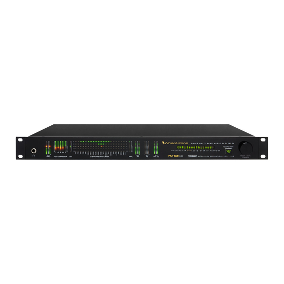
G E N E R A L I N F O R M A T I O N Front Panel Interface In addition to the comprehensive LED metering display, the front panel also hosts a dot matrix display that shows the current preset on the processor as well as a jog wheel, take button and headphone jack. -
Page 22: Basic Setup
G E N E R A L I N F O R M A T I O N Basic Setup Once the processor is rack mounted and connected to a clean source of AC power it is ready for operation. Basic setup and adjustment may be accomplished using the front panel and adjustments to the input and output and preset takes may be made. - Page 23 G E N E R A L I N F O R M A T I O N this, scroll to <PRESET> and press the enter key. To activate a preset, simply press the enter key or the jog wheel once the preset you wish to listen to is displayed. NOTE: Preset names don’t necessarily mean that the preset can or should ONLY be utilized for a program format with a similar name.
-
Page 24: Rear Panel Connections
G E N E R A L I N F O R M A T I O N Rear Panel Connections The image below shows the rear panel of the FM‑531HD and the location of vari‑ ous connectors associated with an installation: All audio input and output, control, Ethernet, and power supply connections are made via connectors on the processor’s rear panel. -
Page 25: Audio Inputs
G E N E R A L I N F O R M A T I O N Audio Inputs The FM‑531HD accepts three types of audio input sources: • Balanced analog line level left/right audio; • Digital AES3 compliant left/right audio with sample rates between 32kHz and 96kHz; •... -
Page 26: Analog Out
G E N E R A L I N F O R M A T I O N Analog Out – XLR-M Pin 1 XLR LT SH – LINE FM LT OUT SH Pin 2 XLR LT HI – LINE FM LT OUT HI Pin 3 XLR LT LO –... -
Page 27: Network Connection
G E N E R A L I N F O R M A T I O N Network Connection The FM‑531HD audio processor has a 100Base‑T Ethernet port on the rear panel. The port is Auto‑MDIX, allowing it to support straight through and cross‑ over cables. -
Page 28: General Purpose Interface (Gpi)
G E N E R A L I N F O R M A T I O N General Purpose Interface (GPI) The FM‑531HD is equipped with eight General Purpose Input (GPI) control input ports on the rear female DB‑9 connector. All GPI connections are optically‑isolated to prevent external ground loops and to prevent dangerous voltages from being intro‑... - Page 29 G E N E R A L I N F O R M A T I O N that have been modified are considered by the system to be “user” presets and therefore must be saved as a new name and in a new preset storage slot. Our advice is to start with a factory preset that has the on air sound that is closest to what you believe you need.
- Page 30 G E N E R A L I N F O R M A T I O N Analog XLR Connections Analog In - XLR-F XLR LT-F PIN 1 XLR LT SH - LINE LT IN SH PIN 2 XLR LT HI - LINE LT IN HI PIN 3 XLR LT LO - LINE LT IN LO XLR RT-F PIN 1 XLR RT SH - LINE RT IN SH...
- Page 31 G E N E R A L I N F O R M A T I O N Digital XLR Connections AES In - XLR-F XLR-F PIN 1 XLR SH - AES IN SH PIN 2 XLR HI - AES IN HI PIN 3 XLR LO - AES IN LO AES Out / baseband192 - XLR-M XLR-M...
- Page 32 G E N E R A L I N F O R M A T I O N BNC Connections PIN 1 BNC 1 HI - SCA 1 IN HI - CENTER PIN PIN 2 BNC 1 SH - SCA 1 IN SH - SHELL BNC - SCA PIN 1 BNC 2 HI - SCA 2 IN HI - CENTER PIN...
- Page 33 G E N E R A L I N F O R M A T I O N Ethernet - RJ-45 RJ-45 ETH TXD + TXD - RXD + RXD - General Purpose Interface - DB-9 GPI - DB-9 GPI 8 IN (+) GPI 7 IN (+) GPI 6 IN (+) GPI 5 IN (+)
- Page 34 F M - 5 3 1 H D G U R U G U I PC Based Audio Processing Guru ® Chapter Contents Installation ..................2-3 Changing FM-531HD’s IP Address Configuration ...... 2-5 Reconfiguring The Remote GUI ........... 2-6 Connecting Directly Without a LAN ..........2-6 About DHCP and FM-531HD ............
- Page 35 F M - 5 3 1 H D G U R U G U I Headphone Source ....................2-18 Headphone Volume Control ...................2-18 Status Indicators ....................2-18 Temp ........................2-18 Analog ........................2-18 Digital .........................2-18 Remote Login ......................2-19 Events ........................2-19 Creating a Weekly Rotation Schedule ..............2-19 Creating a Long Term Rotation Schedule ............2-20 Deleting a Scheduled Event ................2-20 Setting System Time ....................2-21...
-
Page 36: Installation
Next button to proceed. Next the installer will ask where to in- stall the GUI. The default is: C:\Program Files\Wheatstone\FM531HD. The GUI does not modify the registry and does not require external drivers. Therefore it can be run from any folder,... - Page 37 F M - 5 3 1 H D G U R U G U I The GUI may now be started by selecting it from within the PC’s Start Menu Programs list. Once the GUI starts it will appear as below, minus the metering and analysis activity shown below because we haven’t yet connected the GUI to the FM-531HD! In order to communicate with FM-531HD the following conditions...
-
Page 38: Changing Fm-531Hd's Ip Address Configuration
F M - 5 3 1 H D G U R U G U I Changing FM-531HD’s IP Address Configuration The FM‑531HD’s pre‑configured factory default Ethernet Configuration is as follows: Hardware IP Address: 192.168.1.200 Subnet Mask: 255.255.255.0 Gateway: 192.168.1.1 The FM‑531HD’s network configuration can be viewed or changed using the front panel and scrolling to <NETWORK>... -
Page 39: Reconfiguring The Remote Gui
F M - 5 3 1 H D G U R U G U I Reconfiguring The Remote GUI If the IP addresses of the FM‑531HD have been changed from those configured in the remote GUI a few pages ago it will be necessary to go back into the GUI con- figuration and change the IP address for the FM‑531HD device that was originally configured for the remote GUI. -
Page 40: If The Gui "Connected" But The Meters And Analysis Displays Don't Work
F M - 5 3 1 H D G U R U G U I The FM‑531HD’s TCP protocol utilizes a fixed port, port 55900 for control. The FM‑531HD uses UDP for metering and tries to open port 60000 first. If port 60000 is not busy, it uses it. -
Page 41: Using Guru Gui
F M - 5 3 1 H D G U R U G U I Using Guru GUI The GUI may be repositioned on the host computer’s screen by left‑clicking and holding its title bar and dragging the GUI to the desired position. The GUI may also be minimized on the desktop (taken off the screen) and/or closed by way of the fa- miliar Windows controls at the extreme top right. -
Page 42: Input Menu
F M - 5 3 1 H D G U R U G U I Input Menu This is the first tab on the top far left of the GUI, noting that the screen that is cur- rently being displayed is indicated by a red background on the selected tab. The Input Configuration screen shown above contains controls for the Input Audio Source, Automatic Input Failover, Analog Gain and Digital Gain, and L/R Balance controls. -
Page 43: Analog Gain
0.1 mS (100µSec) Note that the smallest increment of delay time adjustment is 100 microseconds. FM‑531HD is also equipped with our Wheatstone® baseband192 digital composite interface which provides a direct, pure digital signal path between the components of the stereo multiplex spectrum and the associated transmitter’s digital FM modulator. With this interface the usual A to D and D to A and/or sample rate conversions are absent resulting in virtually perfect stereo baseband and modulation performance. -
Page 44: Stereo Encoder Menu
F M - 5 3 1 H D G U R U G U I The FM Digital output available as AES3 digital signal or baseband192 digital multiplex signal. The FM AES3 Digital output offers options for applying De‑Emphasis that is complimentary to Pre‑emphasis that may be in use and also allows the digital output to be taken before or after the FM Diversity Delay. -
Page 45: Mpx Process Control
F M - 5 3 1 H D G U R U G U I Composite Clipper – Emulates analog composite clippers but uses a very high sample rate and special algorithms to drasti‑ cally reduce the artifacts caused by analog composite clippers. -
Page 46: Pilot Injection
F M - 5 3 1 H D G U R U G U I There is a 0.5dB resolution available around the control’s zero setting to allow small adjustments in actual MPX Power to compensate for unusual processing settings and how they affect MPX Power. -
Page 47: Presets Menu
F M - 5 3 1 H D G U R U G U I Presets Menu The Presets tab opens a screen where presets may be selected for on air, saved to the processor, or managed through the FM‑531HD’s comprehensive Preset Library Manage- ment utility. -
Page 48: Locking Presets
F M - 5 3 1 H D G U R U G U I Locking Presets Presets stored on the FM‑531HD may be locked by the user to prevent inadvertent overwriting, renaming, or deletion. This is accomplished by opening the Preset Library by clicking on the Library button in the GUI. -
Page 49: Quick Save
F M - 5 3 1 H D G U R U G U I Quick Save (QSave) The FM‑531HD has a unique feature that allows instant comparison of work in progress to a known reference, such as another preset, or some midpoint while adjustments are being made. -
Page 50: System Menu
Wheatstone processors segregate “sound” settings like AGC Drive from “sys- tem” settings like Analog Output Level. However, unlike other processors you may be familiar with, when a Wheatstone preset is saved all currently active parameters are stored with that preset, including system settings. This is an advantage when one wants to change one or more system settings without changing the sound, or change one or more system settings and change the sound. -
Page 51: Headphone Source
F M - 5 3 1 H D G U R U G U I Headphone Source The headphone source may be directed to several points inside the processing chain: • Input: Output of the audio input selector, whether analog or AES input is selected. •... -
Page 52: Remote Login
F M - 5 3 1 H D G U R U G U I Remote Login When Remote Login is clicked, a Login Password prompt box will open as shown below: A remote login password restricts GUI access to an FM‑531HD processor over the Ethernet connection. -
Page 53: Creating A Long Term Rotation Schedule
F M - 5 3 1 H D G U R U G U I The Weekly Rotation window will open as shown on the right. 2. On the left column, select the days that the preset should be selected. Any combination of check boxes may be chosen. -
Page 54: Setting System Time
F M - 5 3 1 H D G U R U G U I Setting System Time Allows the system time of the FM‑531HD’s onboard computer to be set or changed. FM‑531HD’s system time can be synchronized to external time servers (SNTP, or Simple Network Time Protocol) if desired. -
Page 55: Sound Menu
F M - 5 3 1 H D G U R U G U I Sound Menu Selecting the Sound tab will reveal the ten controls of Guru GUI, six for FM and four for HD. It is these simple to use but quite powerful controls that can morph the sound of any Factory preset into over one million different sounds and textures. -
Page 56: Density
F M - 5 3 1 H D G U R U G U I Density The Density control adjusts how much short‑term limiting is permitted. Higher set- tings will make the audio more dense and “processed” sounding while lower settings will be less so. -
Page 57: Hd Sound Adjust
F M - 5 3 1 H D G U R U G U I HD Sound Adjust Density The HD Density control adjusts how much short- term limiting is permitted within the multiband and broadband limiting sections. Higher settings will make the audio more dense and “processed”... -
Page 58: Audio Input And Output Metering
F M - 5 3 1 H D G U R U G U I Audio Input and Output Metering The FM‑531HD provides high resolution level metering for all input and output signals. The topmost pair of horizontal bargraph meters show the applied input levels of the selected audio source, after that source’s Gain control. -
Page 59: Audio Processing Gain Reduction Displays
F M - 5 3 1 H D G U R U G U I Audio Processing Gain Reduction Displays At the bottom of the GUI display are the vertical bars representing the amount of activity occurring in each of the FM‑531HD’s processing sections. The View button on the top-left of the metering section allows you to scale the size of the GUI. -
Page 60: Analysis Menu
FM or HD audio after processing. • SDR™ – Spectral Dynamic Range™ (a Wheatstone exclusive). This display shows the amount of dynamic range remaining in each of the 31 FM or HD limiter bands, after processing. -
Page 61: O-Scope
F M - 5 3 1 H D G U R U G U I With complex program material the FFT gives good visual feedback on the levels of audio residing in different parts of the audio spectrum. O-Scope This is an oscilloscope‑type time‑domain display of the audio waveforms exiting the output of the FM final peak control sections. -
Page 62: 3-D Plot
F M - 5 3 1 H D G U R U G U I 3-D Plot A 3‑D plot of the audio shows the last ten seconds of audio and what the audio levels were at each frequency in the audio spectrum during that time. The 3‑D plot can be very helpful when looking at how the audio spectrum has been behaving over time. -
Page 63: Accessing Menu Options
F M - 5 3 1 H D G U R U G U I Accessing Menu Options Right clicking anywhere on the FM‑531HD Control Panel will open a pop up menu tree with access to various items. The first item in the list is View and it presents the user with several choices for what he wishes to view. - Page 64 F M - 5 3 1 H D P R O G U I FM-531HD Pro GUI Chapter Contents Getting Started ................3-5 Configuring The Pro GUI .............. 3-5 Connecting Directly Without a LAN ................3-6 PC System Requirements ..................3-6 The Really Remote Connection! ................3-6 VPN ..........................3-6 The FM-531HD and Internet Security Concerns ............3-7 About DHCP and The FM-531HD ................3-7...
- Page 65 F M - 5 3 1 H D P R O G U I Multiband AGC Controls ..................3-25 AGC Drive ....................3-25 Gated Mode ....................3-25 AGC Gate Threshold ...................3-25 Band Coupling .....................3-26 AGC Backoff ....................3-26 AGC/Compressor Sidebar Menu ...............3-27 AGC Attack ....................3-27 AGC Release ....................3-27 Compressor Attack ..................3-27 Compressor Release ...................3-27...
- Page 66 F M - 5 3 1 H D P R O G U I VBMS .........................3-35 Drive ......................3-35 Style ......................3-35 Output ......................3-35 VBMS Frequency ..................3-35 VBMS Metering ...................3-36 Digital Output .....................3-36 AES3 Digital ....................3-36 FM Diversity Delay ....................3-36 Entering Delay Values Manually ..............3-37 Stereo Encoder Menu ....................3-37 MPX Processor Style ..................3-37 Composite Clipper ..................3-37...
- Page 67 F M - 5 3 1 H D P R O G U I Side Bar Region ......................3-49 Presets ........................3-49 Save ........................3-49 Library ........................3-50 Locking Presets ....................3-50 How to View Preset Changes ................3-51 Devices ........................3-51 Quick Save (QSave) ....................3-52 Title Bar Region ......................3-53 Status ........................3-53 Device ........................3-53 Preset ........................3-54...
-
Page 68: Getting Started
Just like all of the Wheatstone Pro GUI’s, the FM‑531HD Pro GUI has been carefully designed so that no adjustment is more than two mouse clicks away. -
Page 69: Connecting Directly Without A Lan
GUI, connects to the IP address that is running in the box (NAT takes care of the IP address differences), and Voila! He can adjust his Wheatstone processors from anywhere. We will leave the myriad other ways in which the FM‑531HD can be remotely controlled “wirelessly”... -
Page 70: The Fm-531Hd And Internet Security Concerns
F M - 5 3 1 H D P R O G U I The FM-531HD and Internet Security Concerns The FM‑531HD does not act as a “web device” or “web server,” nor does it sup‑ port open ports to the Internet. Therefore there is no worry that someone could “hack” into the FM‑531HD and use it as a pathway to the rest of the network to which it is connected. -
Page 71: Using The Pro Gui
F M - 5 3 1 H D P R O G U I Using The FM-531HD Pro GUI The GUI may be positioned on the host computer’s screen by left‑clicking and holding the top edge of the Title Bar and dragging the GUI to the desired position. In true Windows fashion, the GUI may be minimized on the desktop (taken off the screen) and/or closed by way of the familiar controls at the extreme top right. -
Page 72: Dynamic Displays Region
Control Area. We’ve worked very hard on the design of the Wheatstone graphical user interface to make it intuitive, friendly, and easy to navigate and interpret in spite of the many number of controls the user has access to (well over 350). - Page 73 F M - 5 3 1 H D P R O G U I By right clicking on the graphical display area with your mouse the following options will appear: First, a short tutorial…. By default, all adjusters (the blue dots) are Grouped. That is they are coupled to each other so that if you grab one with the mouse (single left click and hold) and then slide the mouse up and down, all blue points move up and down together.
- Page 74 F M - 5 3 1 H D P R O G U I After these exercises the line is probably all messed up. You want to put it back to where it was or at least make it all flat again without having to move every single point back, right? But how do you do that? It’s easy ...
-
Page 75: Metering And Analysis
F M - 5 3 1 H D P R O G U I Metering and Analysis The FM‑531HD Pro GUI offers the same analysis options as the Guru GUI. You can open a new graphics window to access the analy‑ sis features by clicking on the Analysis button in the sidebar region. - Page 76 F M - 5 3 1 H D P R O G U I To learn more about the different types of analysis avail‑ able, please see the section on Analysis for an in‑depth look at what the different displays mean and how they can help visually adjust the sound of the FM‑531HD.
-
Page 77: Control Area Region
F M - 5 3 1 H D P R O G U I Control Area Region This is the large enclosed area directly above the graph and meters. The Equalizer section is shown here as an example. All of the knobs, faders, switches, and check boxes affecting the sound of the audio processing are located within this half of the GUI. -
Page 78: Input Setup Menu
F M - 5 3 1 H D P R O G U I INPUT SETUP MENU This is the first tab on the top far left of the Pro GUI. (Note: the screen that is cur‑ rently being displayed is indicated by a green outline on the selection tab). The Input screen contains controls for the input source selection: Automatic Input Failover, Analog and Digital input gain controls, input L/R gain balance, Phase Rota- tor, and the high pass filter. -
Page 79: Analog Input Gain
F M - 5 3 1 H D P R O G U I If the primary source was digital, the analog input will be selected immediately if there are invalid bits in the data stream or missing audio data. Also, the analog input will be selected after 30 seconds of a valid digital data stream having signal levels below ‑48dBFS. -
Page 80: Hpf - High Pass Filter
F M - 5 3 1 H D P R O G U I After passing through the Phase Rotator the same voice appears like the waveform below. Notice how the upper and lower portions of the waveform now have equal distri‑ bution? No information is lost and, more importantly, no harmonic or intermodulation distortion is created by the Phase Rotator. -
Page 81: Equalizer Menu
F M - 5 3 1 H D P R O G U I EQUALIZER MENU The Equalizer tab has four identical and independent bands. Each of the four bands can be switched in or out independently, and is fully adjustable in three ways: Center Frequency —... -
Page 82: Eq Enable
F M - 5 3 1 H D P R O G U I Clicking on the crosshair of a curve (see white arrow) and holding the left mouse but‑ ton down as you drag the mouse will move the curve to any frequency (left or right move) as well as adjust the curve’s level (Boost or Cut) above or below the 0dB reference line (up or down move). -
Page 83: Agc + Sst Menu
What is SST? Unique to Wheatstone models of processing is a special algorithm called SST, which stands for Sweet Spot Technology™ . The SST incorporates control signals from the... -
Page 84: Sst Controls Overview
F M - 5 3 1 H D P R O G U I The automatic gain control (AGC) itself operates in five frequency bands, and its medium‑term operation is a special derivative of the type of program‑related processing occurring in the Compressor algorithms. While the SST section operates in Left/Right mode, the AGC and Compressors operate on the program content’s Sum and Differ‑... -
Page 85: Window Size
F M - 5 3 1 H D P R O G U I Window Size Because the SST is responsible for maintaining the operation of the five band AGC in its “Sweet Spot” the size of that sweet spot needs to be able to be set for different kinds of program requirements. -
Page 86: A Word (Or Two) About Outboard Processors
F M - 5 3 1 H D P R O G U I A Word (or two) About Outboard Processors There are a number of popular outboard AGC/Compressors on the market that have traditionally been used in front of all‑in‑one processors to achieve one or all of the following: •... - Page 87 F M - 5 3 1 H D P R O G U I always practical in this era of downsizing as there aren’t enough warm bodies to do the work. So, for stations that feel they need to use a processor ahead of a ratings encoder, we suggest setting the FM‑531HD multiband control gate between ‑30dB and ‑20dB and placing the SST in Linear mode.
-
Page 88: Multiband Agc Controls
F M - 5 3 1 H D P R O G U I Multiband AGC Controls AGC Drive The AGC Drive control adjusts the amount of signal into the AGC/Compressor, primarily determining the amount of compression that can be achieved. Driving harder (higher numbers) results in a more consistent on air sound, with an increased capabil‑... -
Page 89: Band Coupling
F M - 5 3 1 H D P R O G U I Band Coupling The Coupling control has one specific purpose – to keep the gains of bands 1, 2, 4, and 5 from exceeding the gain of band 3 when those “outer” bands are “ungated.” This prevents unnatural gain rush‑up by those bands when such behavior would be undesir‑... -
Page 90: Agc/Compressor Sidebar Menu
F M - 5 3 1 H D P R O G U I AGC/Compressor Sidebar Menu It should be noted first that all processing bands may be adjusted by first selecting the desired control type tab, and then using the blue dot navigation method covered previously to adjust individual band parameters. -
Page 91: Hd Limiter Menu
F M - 5 3 1 H D P R O G U I L – R gain. This simple step allows you to tailor the audio so that stereo enhancement will occur in bands most critical to the human ear without raising the L – R gain in the entire spectrum, which adds little audible benefit but can aggravate multipath. -
Page 92: Threshold
F M - 5 3 1 H D P R O G U I Threshold The Threshold control determines when limiting will start in a particu‑ lar band. The range for the FM‑531HD limiter threshold control can be adjusted over a 12dB range to offset the 31‑band Limiter Drive. Attack This control determines how quickly the Limiter will respond to audio once it exceeds the limiter threshold. -
Page 93: Limiter Enable
F M - 5 3 1 H D P R O G U I In a conventional peak detector, audio excursions occurring between individual samples are “missed,” and therefore the audio signal is “under read” during this instant. This results in inaccurate peak control. By increasing the sample rate of the detector to oversample the audio waveform only at the detector it becomes possible to read the audio waveform with much higher precision. -
Page 94: Release Time
F M - 5 3 1 H D P R O G U I circuit and its value must be subtracted from any adjustment of 0.5 milliseconds or greater in order to know the actual attack time. Release Time The Release Time controls the primary (fast) release time of the look ahead limiter. -
Page 95: Output
F M - 5 3 1 H D P R O G U I While the two settings may appear to be almost the same, because the transition am‑ plitude is 1dB greater on the soft setting there is a significant difference in how the two VBMS transfer functions sound on actual program material. -
Page 96: L/R Reverse
F M - 5 3 1 H D P R O G U I L/R Reverse The L/R Reverse flips left and right on the HD output to correct for any wiring issues between the two channels. Phase reverse compensates for a known bug in cer- tain software versions of older HD exciters. -
Page 97: 31 Band Fm Limiter Sidebar
F M - 5 3 1 H D P R O G U I 31 Band FM Limiter Sidebar Just like the five band AGC/Compressor, there is a sidebar with some special adjustments available to the user to tailor the sound of the 31‑band limiter. It should be noted first that all bands of audio processing can be adjusted as a group or independently in the sidebar menus. -
Page 98: Vbms
F M - 5 3 1 H D P R O G U I VBMS (Vorsis Bass Management System) The Vorsis Bass Management System allows extremely low program frequencies to be processed without causing dynamic gain changes and without generating undesir‑ able intermodulation artifacts. -
Page 99: Vbms Metering
F M - 5 3 1 H D P R O G U I VBMS Metering There are two ways to monitor the amount of process‑ ing being done by the VBMS. VBMS can be seen on the Analysis Screen on the PRO GUI or in the Guru GUI. -
Page 100: Stereo Encoder Menu
F M - 5 3 1 H D P R O G U I When the Delay controls are both set to their minimum settings, “OFF” appears in the delay window to signal that there is no delay at all in the circuit. Entering Delay Values You can double click on the delay value window to directly enter a numeric delay value in milliseconds. -
Page 101: Look Ahead Limiter
F M - 5 3 1 H D P R O G U I Look Ahead Limiter Uses a 0.5 millisecond look ahead and extremely high sample rates to precisely control composite waveform peaks on a cycle by cycle basis. It works similarly to the oversampled look ahead peak limiter in the FM Limiter screen, only at a far higher sample rate. -
Page 102: Bs412 Mpx Power Controller
In that product, setting the control to -3dB causes a static 3dB reduction in stereo separation regardless of the incoming program material! The Wheatstone approach is more intelligent in how it works; it does not decrease stereo separation on program material that does not need it. -
Page 103: Pilot Injection
F M - 5 3 1 H D P R O G U I by raising its MPX Power detection threshold well above any conceivable or achievable audio density. IMPORTANT! If your station is not required to comply with a Multiplex Power stan- dard where it is licensed to operate, the BS412 control should remain unchecked! Pilot Injection The Pilot Injection control adjusts the level of the... -
Page 104: Analog Output Type
F M - 5 3 1 H D P R O G U I Analog Output Type Please pay careful attention to the following analog output description as it is different from those found in all other broadcast audio processors! Composite MPX When selected, the male XLR outputs and the female BNC connectors assigned to TX 1 and TX 2... -
Page 105: System Menu
F M - 5 3 1 H D P R O G U I SYSTEM MENU The System screen allows system‑wide settings to be configured. In the first third of the screen is a very important box labeled Special Options with two choices. Input/Output Settings Follow Preset Takes When this box is unchecked, recalling presets ignores the settings of the input and output level controls and other system controls associated with those functions. -
Page 106: Metering Data Over Tcp/Ip
F M - 5 3 1 H D P R O G U I Stereo Encoder Screen: Pilot Level Pilot Phase BS412 SCA 1 SCA 2 TX 1 TX 2 Pilot Only Analog ‑ L/R, L/R Deemph, and MPX output style choices The Input/Output Settings Follow Preset Takes choice allows the FM‑531HD to modify its input and output gain settings whenever presets are recalled. -
Page 107: Pro Gui Access
F M - 5 3 1 H D P R O G U I been set. The current password will need to be known beforehand, and it will need to be entered twice for verification. The password can be any combination of characters, numbers, or symbols. -
Page 108: Status Indicators
• Navigate the directory structure of the host PC to find the folder where the GUI has installed its support and configuration settings. By default this will be: C:\Documents and Settings\(logged on user)\My Documents\Wheatstone\FM531HD\maps • Inside the MAPS folder are one or more .cfg (configuration) files named for the devices that the GUI has previously been configured for. -
Page 109: Scheduler
F M - 5 3 1 H D P R O G U I Scheduler The FM‑531HD contains a compre‑ hensive scheduling utility that allows presets to be automatically changed on desired dates and times. There is also a Long Term Rotation utility to allow one time preset changes to be scheduled for any time in the future. -
Page 110: Deleting A Scheduled Event
F M - 5 3 1 H D P R O G U I Deleting a Scheduled Event Deleting a scheduled preset change is as simple as adding one. Open the Event Scheduler window by navigat‑ ing to the System menu and clicking Scheduler. -
Page 111: Headphone Control
F M - 5 3 1 H D P R O G U I Headphone Control On the left side of the front panel of the FM‑531HD is a quarter inch female TRS jack for headphone use. The volume control for the headphone output is located on the lower right side of the Pro GUI. -
Page 112: Side Bar Region
F M - 5 3 1 H D P R O G U I Side Bar Region To the right of the control area is a vertically disposed row of buttons. We will explain each button in turn. Presets When left‑clicked, a dialog box appears, showing folders that contain presets, typi‑... -
Page 113: Library
F M - 5 3 1 H D P R O G U I Library When the Library button is pressed a window‑ style dialog box appears containing three panels. The large panel on the left shows the presets currently stored on the FM‑531HD. -
Page 114: How To View Preset Changes
F M - 5 3 1 H D P R O G U I How to View Preset Changes It is possible to visually compare two different presets on the FM‑531HD with a special feature called Preset Difference. When the Library tab is opened, highlight any preset you’d like to compare with the current preset running on the processor. -
Page 115: Quick Save (Qsave)
F M - 5 3 1 H D P R O G U I Quick Save (QSave) The FM‑531HD has a unique feature that allows instant comparison of work in progress to a known reference, such as another preset, or some midpoint while adjustments are being made. -
Page 116: Title Bar Region
Along the top edge of the FM‑531HD Pro GUI screen (in line with the Wheatstone FM-531HD product label to the left, and the Windows About, Minimize, and Exit icons to the right) are indicators and controls for the management of devices and presets. -
Page 117: Preset
F M - 5 3 1 H D P R O G U I Preset The preset window shows the current preset that is active on the processor. When the preset name is displayed in GREEN text the currently running preset reflects exactly what has been last saved to that preset and that no changes have been made. -
Page 118: Accessing Menu Options
F M - 5 3 1 H D P R O G U I Accessing Menu Options Right clicking anywhere on the FM‑531HD Control Panel will open a pop up menu tree with access to View, Hardware, and Presets choices. These choices lead to sub‑menus and dialog boxes that may also be accessed by clicking on other dedicated buttons on the main FM‑531HD control panel. -
Page 119: Fm-531Hd Hardware Update
FM-531HD Hardware Update The FM‑531HD is extremely easy to update when new firmware becomes avail‑ able from Wheatstone. The file involved in updating the FM‑531HD is called a VBN (Virtual Binary Nugget). This file contains motherboard application code, FPGA images, and DSP code. -
Page 120: Preset Menu Items
F M - 5 3 1 H D P R O G U I Progress boxes will pop up as the download progress occurs: When the system has finished downloading, you will get a prompt to reboot the FM‑531HD. After the FM‑531HD reboots the new VBN code will be running on the motherboard. Presets Menu Items The Presets menu tree may be accessed by right clicking anywhere on the main FM‑531HD Control Panel. -
Page 121: Appendices
Appendix A General Specifications ..............A-3 Appendix B FM-531HD GPI Interface ..............A-9 Appendix C Interpreting Common Audio Processing Terms ......A-12 Background .......................A-12 Audio Terms and Wheatstone Processing ..............A-13 Thump/Rumble/Bottom ..................A-13 Punch/Boom/Tubby/Warm ..................A-14 Mud ........................A-14 Honk ........................A-15 Whack ........................A-15 Fuzzy/Tinny ......................A-15 Crunchy/Edgy ......................A-15 Sibilance .........................A-16... - Page 122 A P P E N D I C E S Appendix A Contents General Specifications ..............A-3 page A – 2 FM-531HD / May 2013...
-
Page 123: General Specifications
Impedance: > 10Kohm (bridging) Optimum Source Impedance: < 1Kohm Digital Line Input Type: AES/EBU (AES3) or Wheatstone AoIP AES Data Amplitude: Per AES3-2003 assuming minimum allowable output signal amplitude of 2V and minimum allowable input signal amplitude of 200mV Input Gain Adjustment Ranges... - Page 124 A P P E N D I C E S Voice Symmetry Phase Rotation Operating Modes: In/Out Filter Type: Order Allpass High-Pass Filter HPF Filter Class: 24dB/octave Butterworth Frequency range: 20Hz – 300Hz Equalizer Frequency: 20Hz – 20kHz Bandwidth: 0.2 – 3.0 octaves Boost / Cut: +/- 14.0dB Options:...
- Page 125 A P P E N D I C E S Multiband Threshold: +/-6dB relative to Multiband Drive setting Multiband Attack Time: 10ms to 100ms Multiband Release Time: 3.0ms to 100ms Look ahead Limiter Drive: +/- 6.0dB Look ahead Limiter Threshold: +/- 6.0dB Look ahead Limiter Attack Time: 0.2ms –...
- Page 126 A P P E N D I C E S Maximum SCA Input Level: +24dBu SCA 1 & 2 Gain Control: -79.95dB to +10dB; OFF TX 1 & 2 Level: -79.95dB to +6.0dB in 0.05dB steps corresponding to baseband192 levels of -85.5dBFS to 0.0dBFS respectively;...
- Page 127 A P P E N D I C E S Day-Parting and Long-term Scheduling A weekly preset scheduling establishes a weekly cycle of preset changes, allowing for automatic programmed day-by-day exclusions or additions. Additionally, a separate long-term scheduling table permits the establishment of one-off preset changes for any future time and date.
-
Page 128: Fm-531Hd Gpi Interface
A P P E N D I C E S Appendix B Contents FM-531HD GPI Interface ..............A-9 page A – 8 FM-531HD / May 2013... -
Page 129: Fm-531Hd Gpi Interface
A P P E N D I C E S FM-531HD GPI Interface The FM-531HD is equipped with a GPI (General Purpose Input) control interface – an eight input optoisolated interface for selecting presets in the first eight memory slots. The GPI interface provides eight separate General Purpose Inputs which share a com- mon DC return. - Page 130 A P P E N D I C E S Applied Voltage to GPI External Resistance 3.3 Volts None 5.0 Volts 330 Ohms 6.0 Volts 470 Ohms 7.5 Volts 820 Ohms 10 Volts 1.3 kOhms 12 Volts 1.8 kOhms 15 Volts 2.4 kOhms 24 Volts 3.9 kOhms...
- Page 131 A P P E N D I C E S Appendix C Contents Interpreting Common Audio Processing Terms ......A-12 Background .......................A-12 Audio Terms and Wheatstone Processing ..............A-13 Thump/Rumble/Bottom ..................A-13 Punch/Boom/Tubby/Warm ..................A-14 Mud ........................A-14 Honk ........................A-15 Whack ........................A-15 Fuzzy/Tinny ......................A-15 Crunchy/Edgy ......................A-15 Sibilance .........................A-16...
-
Page 132: Interpreting Common Audio Processing Terms
“thump” you want will be the “thump” you get and not “tubby.” Please note that some of the controls mentioned on the following pages may not be available on the FM-531HD. The discussion is generic to a wide variety of Wheatstone processor models. -
Page 133: Audio Terms And Wheatstone Processing
Much of the credit for the vast sound-tailoring flexibility and incredibly clean sound of Wheatstone’s FM-531HD processor goes to its 31-band limiter. A 31-band limiter can accomplish two goals that no other limiter with fewer bands can. The first is that it allows the end user to achieve a great deal of loudness without hearing individual limiter bands work. -
Page 134: Punch/Boom/Tubby/Warm
A P P E N D I C E S a very specialized bass system called “VBMS™ ,” which stands for “Vorsis Bass Management System™ .” In general terms VBMS gets real bass on the air without it causing the problems commonly associated with “bass clippers.” . Using VBMS™... -
Page 135: Honk
– placing the 31-band limiters after the FM pre-emphasis for in- stance. In fact, Wheatstone is the only processing company that we are aware of that allows the end user to move the pre-emphasis around. If a particular program format or market dictates that a smoother mid and high frequency range is needed, placing the pre-emphasis BEFORE the multiband limiter can help in this regard. -
Page 136: Sibilance
A P P E N D I C E S Speaking of high end and texture, Wheatstone provides three different main clipper styles in most of our processor models. Each clipper style is specifically designed to create a specific artistic effect while also limiting signal peaks. The three clipper styles... -
Page 137: Finally
Shoot us an email at techsupport@wheatstone.com or give us a call at 252-638-7000. We know our processors inside and out and can make them sit up and dance in any market or format. - Page 138 A P P E N D I C E S Appendix D Contents Using The Factory Lock Utility ............A-19 Background .......................A-19 Installation .........................A-19 Using the Utility ......................A-20 Confirming Factory Lock/Unlock Is Operational ............A-21 Removing The Factory Lock/Unlock Options ............A-22 page A – 18 FM-531HD / May 2013...
-
Page 139: Using The Factory Lock Utility
– the sound that management has paid those consultants to create! As installed, Wheatstone GUI’s offer medium-level preset security, meaning that any preset locked by one user can be unlocked by another. On the other hand, when presets are Factory Locked the GUI is not normally allowed to overwrite or delete those presets from the processor’s hardware because the GUI’s preset library utility does not... -
Page 140: Using The Utility
Using The Utility STOP! ALL WHEATSTONE PROCESSING GUI’S MUST BE CLOSED BEFORE RUNNING THIS UTILITY! There are four files installed into the Factory Lock utility’s folder. -
Page 141: Confirming Factory Lock/Unlock Is Operational
A P P E N D I C E S Once you have reached the folder with the name of the processor, STOP! Click OK to proceed. The utility’s progress window should now say “Done” and the Factory Lock options are now enabled. Confirming Factory Lock/Unlock Is Operational Now it is safe to restart the GUI, so please open it. -
Page 142: Removing The Factory Lock/Unlock Options
A P P E N D I C E S Removing The Factory Lock/Unlock Options It is sometimes useful to undo the Factory Lock options in order to prevent inad- vertent access or preset permissions changes. The Factory Lock utility is used once again, but this time we tell it to remove the Factory preset permissions from the GUI.
Need help?
Do you have a question about the FM-531 HD and is the answer not in the manual?
Questions and answers