Table of Contents
Advertisement
Quick Links
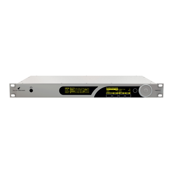
RBRX1
Re-BROADCAST RECEIVER
TECHNICAL MANUAL V. 1.2
No part of this manual may be re-produced in any form without prior written permission from BW Broadcast. The
information and specifications contained in this document is subject to change at any time without notice.
©2012 BW Broadcast
www.bwbroadcast.com
Advertisement
Table of Contents

Related Manuals for BW Broadcast RBRX1

Summary of Contents for BW Broadcast RBRX1
- Page 1 Re-BROADCAST RECEIVER TECHNICAL MANUAL V. 1.2 No part of this manual may be re-produced in any form without prior written permission from BW Broadcast. The information and specifications contained in this document is subject to change at any time without notice.
-
Page 2: Table Of Contents
Contents I Introduction 1 The RBRX1 2 Warranty 3 Safety 4 Quick Start 4.1 FM Rebroadcasting ........ - Page 3 8 Metering and Status 8.1 Metering ......... . . 8.1.1 Main screen .
- Page 4 14 Serial remote 14.1 Using Hyperterminal ........V Processing 15 Processing structure 16 Tuner...
- Page 5 VI Features 18 Managing Presets 18.1 Loading Presets ........18.2 Factory Presets .
- Page 6 21 Log 21.1 Log to File ......... . 21.2 Log to RS232 .
- Page 7 27 Silence Detector with RDS Generation 27.1 Input Switching ........27.1.1 Re-broadcast in case of local downtime .
-
Page 8: I Introduction
Part I Introduction... -
Page 9: The Rbrx1
The RBRX1 front panel control system is state of the art, with two organic LED displays, touch sensitive buttons and a wheel for user input. If placed at a remote site and front panel control not possible the built in web-server allows monitoring and control from anywhere in the world using a web-browser. -
Page 10: Warranty
BW Broadcast shall, at its sole discretion, ei- ther repair or replace the product. If the unit has a manufacturers fault within twenty eight (28) days then BW Broadcast will pay the freight at their discretion. - Page 11 BW Broadcast. Any repair or opening of the unit carried out by unauthorized personnel (user included) will void the warranty. If an inspection of the product by BW Broadcast shows that the defect in question is not covered by the warranty, the inspection costs are payable by the customer.
-
Page 12: Safety
Safety CAUTION: To reduce the risk of electrical shock, do not remove the cover. No user serviceable parts inside. refer servicing to qualified personnel. WARNING: To reduce the risk of fire or electrical shock, do not expose this appliance to rain or moisture. Figure 3.1: This symbol, wherever it appears, alerts you to the presence of unin- sulated dangerous voltage inside the enclosure—voltage that may be sufficient to constitute a risk of shock. - Page 13 Heat: The appliance should be situated away from heat sources such as radiators, heat registers, stoves, or other appliance (including amplifiers) that produce heat. Power Source: The appliance should be connected to a power supply only of the type described in the operating instructions or as marked on the appliance. Grounding or Polarization: Precautions should be taken so that the grounding or polarization means of an appliance is not defeated.
- Page 14 CE CONFORMANCE: This device complies with the requirements of the EEC Council Directives: 93/68/EEC (CE Marking); 73/23/EEC (Safety – low voltage di- rective); 2004/108/EC (electromagnetic compatibility). Conformity is declared to those standards: EN50081-1, EN50082-1. WARNING: This equipment generates, uses, and can radiate radio frequency energy.
-
Page 15: Quick Start
Quick Start 1. Install the RBRX1 into the rack. 2. Connect AC power to the unit, and turn on the power. 3. Connect an antenna to the RF In connector. 4. Connect the appropriate audio outputs. 5. Set the frequency: Tuner ⇒ Frequency 4.1 FM Rebroadcasting... -
Page 16: Connections
Connections Figure 5.1: RBRX1 Front and Back Panels... -
Page 17: Menu Structure
Part II Menu Structure... -
Page 18: Menu Structure
Menu Structure G Tuner H Frequency Sets the tuner frequency in 50kHz steps. H De-emphasis Controls the de-emphasis setting of the received audio. Options are Off, 50 uS (Europe) and 75 uS (USA). H Audio lowpass filter Sets the cut-off frequency for the tuner audio filter. H IF Filter J Bandwidth This parameter allows you to manually set the intermediate frequency filter band- width, or configure it to be automatically adjusted. - Page 19 J USN Release Tc Sets how quickly the high cut algorithm responds to the ultra-sonic noise detector decreasing. H Softmute J Signal Threshold Sets what level the signal needs to drop below to start influencing the amount of soft mute. J Signal Attack Tc Sets how quickly the soft mute responds to the signal level reducing.
- Page 20 J Composite Clipper Controls the drive into the composite clipper which effectively sets the amount of composite clipping. The range of composite clipping is -0.5dB to +2dB. J Pilot Level Sets the level of the composite signals 19 kHz pilot tone. The adjustable range is 6% to 12% and an OFF setting for mono applications.
- Page 21 J TA Setting this parameter to a value greater than zero will test the TA flag by activating the TA flag for that period before deactivating it again. G Triggers H Trigger [1-4] J Enable Enables/disables the trigger. J Preset Select Selects which preset to change to if action is set to change preset. J Send e-mail Selects if an e-mail will be sent when the alarm state changes.
- Page 22 H Screen Lock Code Sets the screen lock code. H Clicker Enables/disables the front panel audio feedback. H Users J Username The username for the remote login. J Password The password for the remote login. H Ethernet J DHCP Sets whether the ethernet is configured manually or by DHCP. J DHCP IP Reads back the DHCP IP address.
- Page 23 J UDP · Enable Enables/disables logging messages to a remote UDP logging/syslog server · IP Sets the IP address where the log messages should be sent via UDP · Port Sets the port where the log messages should be sent via UDP. Disable UDP to change. H About J Serial Number J Software Version Reads back the software version.
-
Page 24: The Front Panel
Part III The Front Panel... -
Page 25: Interface
Interface The RBRX1 has an intuitive interface based around a touch sensitive wheel with a central enter button, an exit button and four soft-key buttons. The action of each soft-key is always indicated on the main screen just above the button. -
Page 26: Metering And Status
The left screen of the unit holds the metering display. The RBRX1 has a very flexible metering system utilizing a high definition OLED display to pro- vide detailed metering of all of the detector measurements. The RBRX1 provides six screens of meters which can be toggled by pressing the ‘METERS’... -
Page 27: Radio Indicators Screen
8.1.3 Radio Indicators screen This screen displays the values of the various RF quality indicators that the tuner measures. These indicators are used as inputs to the DSP signal conditioning block. • Signal (dBuV) RF signal level in dBµV. • Pilot (kHz) Stereo pilot level in kHz •... -
Page 28: Status
8.2 Status The home screen (the right screen) on the RBRX1 is mainly used for parameter adjustment, but the left hand column displays some useful status indications: • The first line shows the name of the currently active preset • DIG: Indicates the presence of an AES/EBU signal connected to the digital audio input of the RBRX1. -
Page 29: Remote Control
Part IV Remote Control... -
Page 30: Ethernet Configuration
Ethernet Configuration The RBRX1 supports static or dynamic IP address allocation. You should check with your network administrator as to which way is best for you to configure your unit. If your network administrator needs the MAC address of your unit, it can be found by navigating to System ⇒... -
Page 31: Web Remote
Using The Web Remote Type the IP Address of the RBRX1 into a web browser to access the Web Remote. Parameters will update on the RBRX1 as the values are changed on the web remote (N.B. -
Page 32: Firmware Update
Reboots the device. Factory Reset Resets the device, all settings will be returned to as they were when the RBRX1 left the factory. Presets and backup audio will be preserved on the internal flash memory. 10.6 Backup Audio Upload Audio File This allows you to upload an audio file, in the .wav format, for use... - Page 33 Download Clicking this symbol next to an existing audio file allows it to be saved onto the computer. Delete Clicking this symbol next to an existing audio file deletes it from the unit’s mem- ory.
-
Page 34: Telnet Remote
Telnet Remote All of the settings on the RBRX1 can be controlled remotely using a telnet interface. To con- figure the telnet interface: 1. First configure the Ethernet interface (Section 9, page 30) 2. Then Navigate to System ⇒ Telnet 3. - Page 35 savePreset < preset_name > [ preset_id ] This commands stores all of the preset parameters to the preset specified. If a preset_id isn’t specified, the unit will generate one based on the name supplied. listPresets This command displays a list of all the presets stored in the unit. listAudioFiles This command displays a list of all the audio files stored in the unit.
-
Page 36: Email
Email The RBRX1 allows the sending of emails to provide notification of an alarm or external trigger being activated. To send email, the RBRX1 needs to be configured with your SMTP server details: 1. Navigate to System ⇒ SMTP. 2. Set the Host and Port to that of the network SMTP server. -
Page 37: Snmp
SNMP The RBRX1 supports SNMPv1. SNMP can be used to centrally manage all SNMP enabled devices on a network. A third party MIB browser must be used to utilise the features offered. To use SNMP: 1. Download the MIB file from your RBRX1: http://IP_Address/api/BWB-RBRX1-MIB.txt 2. -
Page 38: Serial Remote
Serial remote All of the settings on the RBRX1 can be controlled remotely using an RS232 interface. To configure the RS232 interface: 14.1 Using Hyperterminal 1. Set the connection speed preferred on the unit, default is 19200. (System ⇒ RS232 ⇒... - Page 39 The unit can now be controlled by connecting a suitable 9-pin D-way cable from the device to your PC or other RS232 controller. The commands that the RS232 interface are the same as the telnet remote, with the exception that there is no welcome message (Section 11, page 34).
-
Page 40: V Processing
Part V Processing... -
Page 41: Processing Structure
Processing structure The RBRX1 can be used as a high quality off-air reference receiver and as a rebroadcast receiver. The receiver is very sensitive and offers excellent signal selectivity. It is also capable of advanced digital signal processing to produce the best possible audio signal. - Page 42 Figure 15.1: RBRX1 Block Diagram...
-
Page 43: Tuner
This section has more detailed information on setting up the RBRX1 tuner processing. 16.1 IF Filter The RBRX1 has a variable bandwidth adaptive IF filter. This is designed to suppress adjacent channel breakthrough, while minimizing the distortion of the selected channel. The filter can operate in a fixed/manual or in an adaptive/automatic mode. -
Page 44: Stereo Blend
The RBRX1 stereo blend algorithm performs this action, automatically adjusting the amount of blending based on four signal quality detectors. They are: • Signal level •... -
Page 45: High Cut
For poor quality signals additional high frequency cut can further reduce the high frequency noise, at the expense of signal bandwidth. The RBRX1 high cut algorithm performs this action, automatically adjusting the amount of high cut based on three signal quality detectors. -
Page 46: Soft Mute
By progressively attenuating the signal as the noise increases, the perceived effect of the noise can be reduced. The RBRX1 has a “soft mute” algorithm which automatically applies attenuation based on three signal quality detectors. They are: • Signal level •... -
Page 47: Miscellaneous
De-emphasis parameter to the setting appropriate to your region. Setting this parameter incorrectly will result in an overly dull or bright sound. If you are using the RBRX1 to process for FM re-broadcast you will need to disable the de- emphasis filter. -
Page 48: Mpx Generator
17.1 Features 17.1.1 Composite Clipper The composite clipper in the RBRX1 stereo encoder is highly over-sampled and allows you to gain an extra dB or two of modulation loudness when using the multiplex output to drive your FM transmitter. The range of the composite clipper is -0.5 to 2dB. -
Page 49: Vi Features
Part VI Features... -
Page 50: Factory Presets
Managing Presets The RBRX1 has a number of factory presets and provision for over a hundred user presets. The factory presets should provide an excellent template for you to produce user presets. 18.1 Loading Presets Web Remote Navigate to Presets and click the name of the preset desired. -
Page 51: Saving A Preset
18.3.1 Comparing a Preset (Front panel only) When making processing adjustments it is often desirable to compare against the preset you are adjusting. For example you may wish to modify a factory preset and save it as a user preset. 1. -
Page 52: Downloading A Preset
18.5 Downloading a Preset Downloading a preset from the RBRX1 to a computer allows you to back up your custom preset and to upload it to your other units. 18.5.1 With the Web Remote Click Presets and click the download icon next to the name of the preset to download. -
Page 53: Backup Audio
Backup Audio The RBRX1 can play backup audio from internal storage in the case of the main feed failing. PCM Audio files (files ending with the extension .wav) can be loaded onto the unit via the web remote. From the front panel or the remote a playlist can be created. Backup audio playback can be triggered by the alarms, triggers or manually. - Page 54 To trigger playback when the RF signal level drops below a certain threshold: 1. Create a new preset with MPX Source ⇒ Generator ⇒ Source set to BACKUP and the playlist configured to the files you wish to play 2. Navigate to Alarms ⇒ Alarm A (or any other of the alarms) 3.
-
Page 55: Monitoring And Control
Figure 20.1: GPIO D-type connector pinout 20.1 Alarms/Outputs The RBRX1 has four alarms, which can be set to provide status outputs through the opto- coupled GPIO output, or change current preset when a meter exceeds a user defined threshold. On-delay and off-delay settings allow brief breaches of the limit to be ignored. -
Page 56: N-Stage Fallback
20.2.1 Example 1: Single fall-back Scenario The RBRX1 is being used to rebroadcast an FM signal. The broadcaster has a CD player as an alternative audio source. Signal failure conditions Due to loss of power in the main station, the received FM signal is lost. - Page 57 pass Alarm D Default Preset fail pass Alarm C Plan B fail pass Alarm B Plan C fail pass Alarm A Plan D fail Plan E Figure 20.2: Quadruple Fallback System Configuration First of all, prepare a preset called Plan B. In MPX ⇒ Generator ⇒ Source, select DIGITAL IN. Alarm D will be configured to select this preset when an FM signal failure is detected.
-
Page 58: Example 2: Double Fall-Back
(FM signal). 20.2.2 Example 2: Double fall-back Scenario The RBRX1 is being used to rebroadcast an FM signal. The broadcaster has a CD player as an alternative audio source and backup audio files stored in the unit. Signal failure conditions - Due to loss of power in the main station, the received FM signal is lost. - Page 59 pass Alarm D Default Preset fail pass Alarm C Plan B fail Plan C Figure 20.4: Double Fallback Fall-back actions Our Plan B will be to play a CD from a CD player connected to the AES/EBU digital input. Our Plan C will be to play the backup audio files stored in the unit.
-
Page 60: Triggers/Inputs
(FM signal). 20.3 Triggers/Inputs The RBRX1 has four opto-coupled inputs which allow external signals to change the current preset. The inputs are activated by pulling the pin low. If more than one trigger is active at the same time and configured to produce conflicting behaviour, the lower trigger number gets priority (external triggers are higher priority than internal (i.e. -
Page 61: Log To File
The RBRX1 has a comprehensive set of logging features 21.1 Log to File System ⇒ Log ⇒ File. System log messages are stored on the RBRX1’s internal flash memory. Log files are retained for thirty days, starting a new file at 00:00:00hrs each day. The files can be retrieved using a web browser: •... -
Page 62: Setting The Time
Scheduling Your processor contains a battery backed up real time clock that can maintain the current time and date even when the power has been removed. This allows users to switch between presets at specific times of the day, week or month. This is very useful on a multi-format radio station where one processing preset may not suit all of the formats of music that are broadcast. -
Page 63: Security Code Lock
Security Code Lock The RBRX1 has a security lock code which allows the front panel controls to be locked from users without the code. To configure the lock code: 1. Navigate to System 2. Set Screen Lock Code to your security lock code 3. -
Page 64: Software Update
Software Update The RBRX1 is designed to allow features to be added to the unit in the field via a software update mechanism. You can register to receive email alerts when new software updates become available at www.bwbroadcast.com. Updates are installed using the Ethernet web remote. -
Page 65: Vii Usage Cases
Part VII Usage Cases... -
Page 66: Re-Broadcast Receiver
2. Navigate to Tuner to set the frequency to the station that you wish to rebroadcast. MPX Output 1 on the back of the RBRX1 now has a clean, regenerated stereo and RDS multiplex signal at +4dBu ready to be connected to your FM exciter/transmitter. If you require a different signal level, just navigate to MPX ⇒... -
Page 67: With Backup Audio
25.3 With backup audio 1. Set up the receiver for rebroadcast and ensure the preset is saved: (a) Press the Save ⇒ New softkeys and name the main preset. 2. Set up the receiver as if the alarm had been activated: (a) Set the MPX ⇒... - Page 68 (a) Navigate to Triggers ⇒ Trigger 1 (b) Set Active to Enable. (c) Set the Action to Change Preset and select the backup preset.
-
Page 69: Reference Receiver
Reference Receiver Setting up the RBRX1 for use as a high quality receiver: 1. Press the Load softkey and select the Clean preset. 2. Navigate to the Tuner menu to set the frequency to the station that you wish to receive. -
Page 70: Silence Detector With Rds Generation
Silence Detector with RDS Generation The RBRX1 is the ideal silence detector and with RDS generation ensures your station is kept on the dial. With options for backup audio playlists, rebroadcasting of parent station or switching between analogue and digital inputs, silence is a thing of the past. GPIO alert pin outs let you customise your alert solution. -
Page 71: In Case Of External Trigger Activation
27.1.4 In case of external trigger activation (a) Navigate to Triggers ⇒ Trigger 1 (b) Set Active to Enable. (c) Set the Action to Change Preset and select the backup preset. -
Page 72: Specifications
Part VIII Specifications... -
Page 73: Specifications
RF Performance Many receiver manufacturers quote static specifications based on ideal conditions. With the RBRX1, the inner ’black box’ workings of the NXP DSP demodulator are proprietary. With its patented Sony noise reduction and BW Broadcast’s audio processing technologies, the RBRX1 is continuously adjusting the radio and audio behaviour for optimum performance under given conditions. - Page 74 MPX Output L / R Crosstalk: <= -70dB, 20 Hz-15kHz. Distortion: <= 0.01% THD (Bypass preset, de- emphasised) 20 Hz-15kHz bandwidth. Connectors: XLR male. Pin 1 chassis ground, pins 2 (+) and 3 (-) electronically balanced, Source Impedance: 10Ω Single-ended, float- floating and symmetrical.
- Page 75 Remote Control Other Serial Port: DB9 (rear panel) Software ad- justable speed: 9600, 19200, 38400, 57600 or 115200kbps. Ethernet Port: 10/100Mbps on RJ45 female connector. Voltage: 100–240 VAC, 50–60 Hz, 35 VA. Trigger Inputs: DB9 opto-isolated and float- Connector: IEC. Detachable 3-wire power ing.
- Page 76 Parameters G Tuner H Frequency tuner.frequency H De-emphasis tuner.deemphasis H Audio lowpass filter tuner.audio_filter.cutoff H IF Filter J Bandwidth tuner.if_filter.bandwidth J Default Bandwidth tuner.if_filter.default_bandwidth J Min Bandwidth tuner.if_filter.min_bandwidth J Threshold Extension tuner.if_filter.threshold_extension J Max Bandwidth Boost tuner.if_filter.max_boost H Stereo Blend J Stereo Width tuner.stereo_blend.stereo J Signal Threshold tuner.stereo_blend.signal.start J Signal Attack Tc tuner.stereo_blend.signal.attack...
- Page 77 J Output Level audioio.digital.output.level J Output Sample Rate audioio.digital.output.samplerate J Input Gain audioio.digital.input.gain H Analog J Output Source audioio.analog.output.source J Output Level audioio.analog.output.level J Input Gain audioio.analog.input.gain H Backup J Playlist[1-10] audio_files.playlist[1] G Mixer H Analog Gain mixer.analog.level H Digital Gain mixer.digital.level H Tuner Gain mixer.tuner.level G MPX H Generator...
- Page 78 J PTY Source rds.dsn[1].psn[0].pty_rbds.source J PTY (RBDS) rds.dsn[1].psn[0].pty_rbds J Local PTY Flag (RDS) rds.dsn[1].psn[0].pty_rds J PTYN Flag source rds.dsn[1].psn[0].ptyn.source J Local PTYN Flag rds.dsn[1].psn[0].ptyn J RT source rds.dsn[1].psn[0].rt.source J RT rds.dsn[1].psn[0].rt J AF · Source rds.dsn[1].psn[0].af.source · Count rds.dsn[1].psn[0].af.count · [1-13]B rds.dsn[1].psn[0].af.1b ·...
- Page 79 H Contact system.contact H Screen Saver system.screen.timeout H Screen Lock system.screen.lock.enabled H Screen Lock Code system.screen.lock.code H Clicker system.clicker H Users J Username system.username.admin J Password system.password.admin H Ethernet J DHCP system.ethernet.dhcp J DHCP IP system.ethernet.dhcp.ip J DHCP SM system.ethernet.dhcp.sm J DHCP GW system.ethernet.dhcp.gw J DHCP DNS 1 system.ethernet.dhcp.dns[1] J DHCP DNS 2 system.ethernet.dhcp.dns[2]...
- Page 80 · IP system.logging.udp.ip · Port system.logging.udp.port H About J Serial Number system.serial_number J Software Version system.software.version J Control Version system.control.version J Digital Version system.digital.version H Reboot system.reboot H Factory Reset system.factory_reset...
Need help?
Do you have a question about the RBRX1 and is the answer not in the manual?
Questions and answers