Table of Contents
Advertisement
Quick Links
Advertisement
Table of Contents

Related Manuals for Sugon TC6600

Summary of Contents for Sugon TC6600
- Page 1 TC6600 U s e r ' s M a n u a l DAWNING INFORMATION INDUSTRY CO.,LTD.
-
Page 2: Statement
The non-Sugon website information mentioned in this manual isprovided for the convenience. Such website information is not a part of product materials of Sugon or a part of services provided by Sugon. Hence, Sugon will not guarantee the accuracy and availability of such website information. Users shall assume the risk of using such website by themselves. -
Page 3: Trademark And Copyright
Sugon, or stored in the retrieval system in any form, or transmitted over the wired or wireless network, or translated into any text in any way. -
Page 4: Operating Instruction For Power Supply
For several servers connecting to the same power supply are needed to lead a large amount of electric current into underground, Sugon suggests the used PDU is connected to the branch circuit of buildings fixedly or equipped with one non-detachable wire which is connected with the industrial plug. All plugs which comply with the IEC 60309 standard shall be considered as applicable plugs. - Page 5 Electrostatic Discharge Electrostatic Discharge Prevention In order to prevent from damaging the system, it is necessary to take necessary precautions when you install the system or take out/put in the component. The static electricity discharged by fingers or other conductors may damage the main board or other electrostatic sensitive equipment.
- Page 6 Combine with the use of dissipative static folding tool pad and portable field maintenance kit.
-
Page 7: Dangerous Warning Statement
Dangerous Warning Statement [Warning] This product is of the grade A product. The product may cause the radio interference in the living environment. In this case, it may require users take practical measures to prevent the interference. The current in the power supply, telephone and communication cable is dangerous. In order to eliminate the risk of electric shock: ... - Page 8 Operate in the interior of power-on server. [Warning] When the server is powered on, the static electricity discharged into the internal components of the server may cause the server to abort abnormally, which may cause data loss. To prevent this potential problem, please always use the ESD wrist strap or other grounding systems when you operate inside the power-on server.
- Page 9 protection function. Always plug the power cord into the nearby accessible grounding power socket. Unplug the power cord to disconnect the power supply of the equipment. Do not put power cord in a place where it is easy to be stepped on or squeezed by the object beside it. Special attention shall be paid to the plug, power socket and the connection point between power line and server.
-
Page 10: Table Of Contents
Table of Contents Statement ..........................ii Trademark and Copyright....................iii Operating Instruction for Power Supply ................iv Dangerous Warning Statement ..................vii Table of Contents ........................ x List of Figures ........................xiii List of Tables ........................xvii 1 Product Profile ......................... 1 1.1 Product Overview .................... - Page 11 2.2.5 Insertion/Pull-out of Fan Module ....................20 2.2.6 Assembly/Disassembly of CPU Blade ..................29 2.2.7 Switch On/Off Power ........................38 2.2.8 Power Connection ........................38 2.2.9 Shut Down Blade System ......................38 2.2.10 Boot Operation of CPU Blade ..................39 2.2.11 Shutdown Operation of CPU Blade ................
- Page 12 5.6 Remote Maintenance (Firmware upgrade) ............115 Appendix - Glossary ......................117 Appendix 2: Abbreviations....................121...
-
Page 13: List Of Figures
List of Figures Figure 2-1 Front Panel Assembly .......................... 12 Figure 2-2 Rear View of Blade Chassis ......................... 13 Figure 2-3Panel of Management Module ......................14 Figure 2-4Front View of Power Module ......................... 16 Figure 2-5Schematic Diagram of Fan Module ....................... 17 Figure 2-6Installation of Carriage Rail ........................ - Page 14 Figure 3-8PCI Subsystem Settings Menu ......................50 Figure 3-9Network Stack Configuration Menu ....................... 51 Figure 3-10CSM Configuration Menu ........................52 Figure 3-11Chipset Menu ............................53 Figure 3-12ProcessorConfiguration Menu ......................54 Figure 3-13Advanced Power Management Menu ....................55 Figure 3-14QPI Configuration Menu ........................56 Figure 3-15Memory Configuration Menu .......................
- Page 15 Figure 3-45APM Configuration Menu ........................86 Figure 3-46Boot Menu ............................87 Figure 3-47Security Menu ............................. 88 Figure 3-48Chipset Menu ............................89 Figure 3-49Exit Menu ............................90 Figure 3-50SAS Configuration Interface ........................ 91 Figure 3-51RAID Creation Interface ........................91 Figure 3-52RAID1 Creation Completion Interface ....................92 Figure 3-53Complete RAID Configuration ......................
- Page 16 Figure 5-21SMTP Settings ........................... 113 Figure 5-22User Management - Delete User ......................113 Figure 5-23Add User ............................114 Figure 5-24Event Log ............................114 Figure 5-25User Operation Log ..........................114 Figure 5-26Firmware Upgrade - Boot ........................115...
- Page 17 List of Tables Table 1-1Technical Specification Description ......................5 Table 1-2 Technical Specification Description of CB50-G20 Blade ................6 Table 1-3Technical Specification Description of CB80-G20 Blade ................8 Table 1-4Technical Specification of CB85-G10 Blade ....................9 Table 1-5Description of Environment Parameters ....................10 Table 1-6Description of Power Parameters ......................
- Page 18 Table 3-23Description of Security .......................... 59 Table 3-24Description of Boot Menu Configuration ....................60 Table 3-25Description of Save & Exit Configuration ....................61 Table 3-26Interface Description of Main Menu ...................... 62 Table 3-27Interface Description of Advanced Menu ....................63 Table 3-28Interface Description of ACPI ........................ 64 Table 3-29Interface Description of Serial Port Console Redirection ..............
-
Page 20: Product Profile
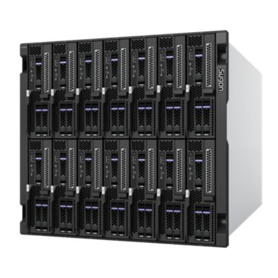
You will be able to understand the product feature, technical characteristic and performance index of the Sugon TC6600 blade server in this chapter, so that you can get a more profound experience over the excellent performance of the TC6600 blade server. -
Page 21: 1.2.1 Technical Characteristics
1.2.1 Technical Characteristics Modular Blade Chassis with High Density The 10U rack space can provide 14 CPU blades (2-socket) or 7 CPU blades (4-socket). Support the mixed interpolation of the 2-socket blade and the 4-socket blade, and provide more user usage patterns. -
Page 22: 1.2.2 Reliability, Availability And Maintainability
Allow access to, install, configure and control the remote blade server from the desktop or any other place. Low network bandwidth is needed to eliminate the restriction of blade server system management and use area, thus accelerating response to the challenge in terms of the reaction speed. - Page 23 Develop the daughter card independently. Support the 10GbE network, FC network and Infiniband network. For the mainstream Ethernet, the Infiniband equipment vendor provides the switching technology and module that complies with TC6600. Multi-level power consumption management and energy saving technology ...
-
Page 24: 1.3 Product Specification
The switching module can support the FC and Ethernet protocols. Provide users with the aggregation Ethernet. Maintainability TC6600 takes the scientific architecture design. The design concept takes the industry standard components as far as possible. It takes the modular design. -
Page 25: Table 1-2 Technical Specification Description Of Cb50-G20 Blade
For the operating system compatibility is related with the configured blade model, Compatible operating please refer to the technical white paper of relevant blade model. For more information, please consult the sales representative of Sugon or the customer system service hotline of Sugon. Table 1-2 Technical Specification Description of CB50-G20 Blade... - Page 26 VMware ESXI 5.X refer Software The operating system compatibility is closely related to the system configuration. For more information, please consult the sales representative of Sugon or the Compatibility List of TC6600 customer service hotline of Sugon. Blade Server). Table 1-3 Technical Specification Description of CB50-S20 Blade...
-
Page 27: Table 1-3Technical Specification Description Of Cb80-G20 Blade
The operating system compatibility is closely related to the system configuration. refer Software For more information, please consult the sales representative of Sugon or the Compatibility List of TC6600 customer service hotline of Sugon. Blade Server). Table 1-4Technical Specification Description of CB80-G20 Blade... -
Page 28: Table 1-4Technical Specification Of Cb85-G10 Blade
Compatibility List of TC6600 The operating system compatibility is closely related to the system configuration. Blade Server). For more information, please consult the sales representative of Sugon or the customer service hotline of Sugon. Table 1-6Technical Specification of CB85-G10 Blade... -
Page 29: Application Environment Of Products
Compatibility List of TC6600 The operating system compatibility is closely related to the system configuration. Blade Server). For more information, please consult the sales representative of Sugon or the customer service hotline of Sugon. Note: DAWNING INFORMATION INDUSTRY CO., LTD. reserves the right to change the configuration without prior notice to users. -
Page 30: Product Structure And Installation
You will be able to understand the basic structure and principle, correct connection mode and considerations for the safety operation of the TC6600 blade server in this chapter. Reading this chapter carefully will be of great help to operate the TC6600 blade server safely and stably. 2.1 Product Composition 2.1.1... -
Page 31: Rear Panel Assembly
Figure 2-1 Front Panel Assembly Table 2-1Description of Front Panel Assembly Components Instructions Name PCIE baffle One standard PCIE card may be installed here. Hard Disk Bay It is used to install the 2.5'' hard disk. It is used for the power on/off operation of the CPU blade. The key-press time Power BUTTON during the power-on is less than 3S, and the key-press time during the power-off is more than 5S. -
Page 32: Figure 2-2 Rear View Of Blade Chassis
Figure 2-2 Rear View of Blade Chassis Table 2-2Modules Description for Rear View of Blade Chassis Module Name Instructions It is used for the system power supply, and up to 6 power modules may Power Module be configured. Fan Module It is used for the heat dissipation of the blade server system. -
Page 33: Management And Switching Module
Module Name Instructions the 2-socket blade. Support installing the 10G direct-connect,10G switching, FC switching Switching direct-connect module and 1G switching module, corresponding to the daughter card module slot 4 Mezz2 and Mez4 in the 4-socket blade and the daughter card Mezz2 in the 2-socket blade. -
Page 34: Power Module
The low speed switching will switch the 1G network of the CPU blade in the chassis. Furthermore, it can switch with the external network. 2.1.4 Power Module The TC6600 blade system provides up to 6 power modules. Furthermore, the power module will provide different redundancy modes according to different configurations of the CPU blade, for... -
Page 35: Fan Module
Figure 2-4Front View of Power Module 2.1.5 Fan Module The TC6600 blade system provides up to 10 fan modules, and the fan module provides the heat dissipation support for the whole system. [Note] Ensure all heat dissipation modules are installed correctly and operate normally. -
Page 36: 2.2 Disassembly Of Product Chassis And Main Components
Figure 2-5Schematic Diagram of Fan Module 2.2 Disassembly of Product Chassis and Main Components This section will introduce the installation steps and considerations of the TC6600 blade server of Sugon. Please install the TC6600 blade server of Sugon in accordance with the requirement. -
Page 37: Installation Of Carriage Rail
The TC6600 blade server will be equipped with the dedicated carriage rail of the blade server when users purchase it, and the blade server may be installed in the standard 19'' cabinet by the dedicated carriage rail of the blade server. -
Page 38: Blade Server Putaway
attention to the coordination between screw holes during the installation of the carriage rail. Step 3: Tighten six screws in the circle 1 after the carriage rail is fixed appropriately. Figure 2-6Installation of Carriage Rail 2.2.3 Blade Server Putaway After all modules are removed, raise the blade chassis to the position of the blade carriage rail, and then insert it in the depth direction until the front panel of the blade chassis is flush with the rack angle gauge plane, finally fix the lug screw of the blade chassis. -
Page 39: Insertion/Pull-Out Of Blade System Module
The TC6600 blade system includes the following hot swap modules, such as the power module, fan module, management module and low speed module. Refer to Section 2.1.1 "Front View" and Section 2.1.2 "Rear View"... -
Page 40: Figure 2-8Insertion/Pull-Out Of Fan Module
Figure 2-8Insertion/Pull-out of Fan Module Insertion/Pull-out of Management and Switching Module As shown in Figure 2-9, follow the steps below to insert/pull out the management module. Step 1: Turn the knob in the arrow direction ①. Step 2: Pull out the limit handle in the arrow direction ②. Step 3: Pull out the module in the arrow direction ③. -
Page 41: Figure 2-9Insertion/Pull-Out Of Management Module
Figure 2-9Insertion/Pull-out of Management Module Insertion/Pull-out of Switching and Direct-connect Module... -
Page 42: Figure 2-10Insertion/Pull-Out Of Switching And Direct-Connect Module
As shown in Figure 2-10, follow the steps below to insert/pull out the direct-connect or switching module. Step 1: Open limit the handle in the arrow direction ①. Step 2: Pull out the limit handle in the arrow direction ②. Step 3: Pull out the module by the limit handle. -
Page 43: Figure 2-11Insertion/Pull-Out Of Power Module
Figure 2-11Insertion/Pull-out of Power Module Insertion/Pull-out of 2-socket CPU Blade As shown in Figure 2-12, follow the steps below to insert/pull out the 2-socket CPU blade. Step 1: Please follow the direction of arrow ① to open the handle. Step 2: Please follow the direction of arrow ② to pull up the handle. Step 3: Please Install the CPU blade in the oppsite way. -
Page 44: Figure 2-12Insertion/Pull-Out Of 2-Socket Cpu Blade
Figure 2-12Insertion/Pull-out of 2-socket CPU Blade Insertion/Pull-out of 2-socket storage CPU Blade As shown in Figure 2-13, follow the steps below to insert/pull out the 2-socket storage CPU blade. Step 1: Please follow the direction of arrow ① to open the handle. Step 2: Please follow the direction of arrow ②... - Page 45 Figure 2-13Insert/Pull-out of 2-socket storage CPU Blade Insertion/Pull-out of 4-socket CPU Blade As shown in Figure 2-14, follow the steps below to insert/pull out the 4-socket CPU blade. Step 1: Please follow the direction of arrow ① to open the handle. Step 2: Please follow the direction of arrow ②...
-
Page 46: Figure 2-13Insertion/Pull-Out Of 4-Socket Cpu Blade
Figure 2-14Insertion/Pull-out of 4-socket CPU Blade Assembly/Disassembly of 2-socket CPU Blade Chassis Cover As shown in Figure 2-15, follow the steps below to assemble/disassemble the 2-socket CPU blade chassis cover. Step 1: Please follow the direction of arrow ① to loosen the chassis cover by pressing down the button. -
Page 47: Figure 2-14Assembly/Disassembly Of Cpu Blade Chassis Cover
Figure 2-15Assembly/Disassembly of CPU Blade Chassis Cover Assembly/Disassembly of 4-socket CPU Blade Chassis Cover As shown in Figure 2-16, follow the steps below to assemble/disassemble the 4-socket CPU blade chassis cover. Step 1: Press down the button at the arrow ① to loosen the chassis cover. Step 2: Slide to open the chassis cover in the arrow direction ②. -
Page 48: Assembly/Disassembly Of Cpu Blade
2.2.6 Assembly/Disassembly of CPU Blade CB50-G20 is one of the 2-socket Intel CPU blades supported by the TC6600 system. For the specific specification of this CPU blade, please refer to Technical White Paper of Sugon's TC6600 Blade Server provided in the official website of Sugon. -
Page 49: Figure 2-17Open Cpu Lock Lever
Figure 2-18Open CPU Lock Lever Step 3: Open the protective cover of CPU completely (don't touch the CPU and Socket pins). As shown in Figure 2-19. Figure 2-19Open Protective Cover of CPU Step 4: Put the CPU into the CPU slot of the mainboard. Note that the golden triangle on the front of CPU shall be placed in the position as shown in the figure below, so that the positioning key on the slot is positioned in the groove of CPU. -
Page 50: Figure 2-20Close Cpu Seat Clip
Figure 2-21Close CPU Seat Clip Installation of CPU Heat Sink Cover the heat sink over the installed CPU vertically, and tighten four clamping screws. [Note] Check whether the thermal grease at the bottom of the radiator is coated before installing the heat sink. - Page 51 Memory Amount ● ● ● ● ● ● ● ● CPU0_DIMMA1 ● ● ● ● CPU0_DIMMA2 ● ● ● ● ● ● ● CPU0_DIMMB1 ● ● ● CPU0_DIMMB2 ● ● ● ● ● ● CPU0_DIMMC1 ● ● CPU0_DIMMC2 ● ● ●...
-
Page 52: Figure 2-22Memory Channel Rule Of Cb80-G20 Cpu Blade
Figure 2-23Memory Channel Rule of CB80-G20 CPU Blade Table 2-5Memory Channel Rule of 5 Blades Memory Amount ● ● ● ● ● ● ● ● CPU0_DIMMA1 ● ● ● ● CPU0_DIMMA2 ● ● ● ● ● ● ● CPU0_DIMMB1 ● ●... - Page 53 Memory Amount ● ● ● ● ● ● ● ● CPU1_DIMMA1 ● ● ● ● CPU1_DIMMA2 ● ● ● ● ● ● ● CPU1_DIMMB1 ● ● ● CPU1_DIMMB2 ● ● ● ● ● ● CPU1_DIMMC1 ● ● CPU1_DIMMC2 ● ● ●...
-
Page 54: Figure 2-23Memory Channel Rule Of Cb85-G10 Cpu Blade
Memory Amount ● ● ● CPU3_DIMMC2 ● ● ● ● ● ● CPU3_DIMMD1 ● CPU3_DIMMD2 ● ● ● ● ● CPU3_DIMME1 ● ● ● ● ● CPU3_DIMMF1 ● ● ● ● ● CPU3_DIMMG1 ● ● ● ● ● CPU3_DIMMH1 Memory ●... -
Page 55: Table 2-6Memory Channel Rule Of Blade
Table 2-6Memory Channel Rule of Blade Memory Amount ● ● ● ● ● ● ● ● CPU0_DIMMA0 ● ● ● ● CPU0_DIMMA1 ● ● ● ● ● ● ● CPU0_DIMMB0 ● ● ● CPU0_DIMMB1 ● ● ● ● ● ● CPU0_DIMMC0 ●... -
Page 56: Figure 2-24Memory Installation
Memory Amount ● ● ● ● ● ● CPU3_DIMMC0 ● ● CPU3_DIMMC1 ● ● ● ● ● CPU3_DIMMD0 ● CPU3_DIMMD1 Memory Illustration Memory is inserted. inserted. Follow the steps below to install the memory. Step 1: Insert the memory module into the memory slot vertically. There is only one gap in the middle of the memory module, and the memory module can be inserted in the right direction only. -
Page 57: Switch On/Off Power
Figure 2-26Assembly/Disassembly of Hard Disk Bracket Step 3: Install the hard disk bracket in the reverse procedure. Pay attention to connecting the hard disk with the mainboard closely during the installation. 2.2.7 Switch On/Off Power This section mainly describes the power connection of the blade chassis and how to start and shut down the blade system. -
Page 58: 2.2.10 Boot Operation Of Cpu Blade
2.2.10 Boot Operation of CPU Blade The schematic diagram of the front panel for the CB50-G20 CPU blade is shown inFigure 2-27. Figure 2-27Front Panel of CPU Blade After the blade system chassis is opened, start each CPU blade in the following two ways. ... -
Page 59: 2.2.11 Shutdown Operation Of Cpu Blade
the IP address, user name and password set by yourself); log in the management interface, and enter the blade interface of the system management. Click the CPU blade to be started and select Start to start the CPU blade. 2.2.11 Shutdown Operation of CPU Blade The shutdown may be implemented in the following three methods. -
Page 60: Product Configuration
3 Product Configuration 3.1 Jumper Settings [Note] For the actual product may carry out the version upgrade, the illustration in this section is for reference only. The actual hardware product of users shall prevail. 3.1.1 Jumper Settings of CB50-G20 CPU Blade Figure 3-1 is the jumper position identification of the CB50-G20 CPU blade, and table 3-1 is the function description of each jumper. -
Page 61: Jumper Settings Of Cb80-G20 Cpu Blade
Table 3-2Jumper Setting Method Icon Description Explanation OPEN - Jumper OFF Don't connect to jumper CLOSED - Jumper ON Connect to jumper Table 3-3Description of Jumper Setting for CB50-G20 CPU Blade Icon Description 1-2: Normal (Default) 2-3: Correspond to relevant mode in Table 3-1. 3.1.2 Jumper Settings of CB80-G20 CPU Blade Figure 3-2 is the jumper position identification of the CB80-G20 CPU blade,... -
Page 62: Jumper Setting Of Cb85-G10 Cpu Blade
Table 3-4Description of CB80-G20 Jumper Jumper Name Function 1-2 Normal (Default) 2-3 RTC reset 1-2 Normal (Default) 2-3 Password clear 1-2 Normal (Default) 2-3 Manufacture mode 1-2 Normal (Default) 2-3 ME force update Table 3-5Description of Jumper Setting for CB80-G20 CPU Blade Icon Description 1-2: Normal (Default) -
Page 63: Figure 3-3Jumper Setting Of Cb85-G10 Mainboard
Figure 3-3Jumper Setting of CB85-G10 Mainboard Table 3-6Description of CB85-G10 Jumper Jumper Name Function 1-2 Normal (Default) 2-3 Password clear 1-2 Normal (Default) 2-3 RTC reset 1-2 Normal (Default) 2-3 Recover BIOS Table 3-7Jumper Setting Description of CB85-G10 CPU Blade Icon Description 1-2: Normal (Default) -
Page 64: 3.2 Bios Setup
3.2 BIOS Setup 3.2.1 BIOS System Setup Method Power on to start the server, and press the <Del> key, and the system enters the BIOS setup program. You can select the sub item by the arrow direction key in the BIOS main menu, and hit the Enter key to enter the submenu. -
Page 65: Figure 3-4Main Menu
Figure 3-4Main Menu Figure 3-4 is the configuration content of the Main option, which is described as follows. Table 3-9Interface Description of Main Menu Interface Parameters Function Description BIOS Information Display the current information of BIOS. Board Information Display the mainboard information. Language type used by the BIOS Setup interface System Language System Date&time... -
Page 66: Figure 3-5Advanced Menu
Figure 3-5Advanced Menu Figure 3-5 is the content of the Advanced menu, which is described as follows: Table 3-10Interface Description of Advanced Menu Interface Parameters Function Description ACPI Settings ACPI settings, including Hibernate and Lock Legacy Resource. etc. Serial Port Console Redirection Relevant serial port settings PCI Subsystem Settings Set the PCI relevant parameters. -
Page 67: Figure 3-6Acpi Menu
Figure 3-6 is the ACPI settings menu: Figure 3-6ACPI Menu Table 3-11Interface Description of ACPI Interface Parameters Function Description Enable ACPI Auto Configuration ACPI auto configuration Enable Hibernation Hibernation Prevent the operating system from changing the serial port, parallel port or Lock Legacy Resources relevant resource of the disk controller. -
Page 68: Figure 3-7Serial Port Console Redirection Menu
Figure 3-7 is the Serial Port Console Redirection setting menu Figure 3-7Serial Port Console Redirection Menu Table 3-12Interface Description of Serial Port Console Redirection Interface Parameters Description (COM0) Console Enable/Disable the COM0 console redirection. Redirection (COM0) Console COM0 console redirection settings Redirection Settings (COM1) Console... -
Page 69: Figure 3-8Pci Subsystem Settingsmenu
Figure 3-8 is the menu: PCI Subsystem Settings Figure 3-8PCI Subsystem SettingsMenu Table 3-13Interface Description of PCI Subsystem Settings Interface Parameters Function Description Above 4G memory address space access switch, which supports above 4G Above 4G Decoding address space decoding of the 64-bit PCI device. SR-IOV Support Virtualization function control switch of PCIE device... -
Page 70: Figure 3-9Network Stack Configurationmenu
Figure 3-9 is the settings menu: Network Stack Configuration Figure 3-9Network Stack ConfigurationMenu Table 3-14Interface Description of Network Stack Configuration Interface Parameters Function Description Set whether to enable UEFI PXE to support the network stack (need to be Network Stack supported by the network device UEFI Driver). -
Page 71: Figure 3-10Csm Configurationmenu
Figure 3-10CSM ConfigurationMenu Table 3-15Interface Description of CSM Configuration Interface Parameters Function Description CSM Support Set whether to enable the module compatibility support. CSM Module Version Display the CSM module version. Select the information display mode of Option ROM. [Force BIOS]- The third party ROM information will be displayed forcibly during the startup. -
Page 72: Figure 3-11Chipset Menu
Interface Parameters Function Description opROM PCIE Slot Set whether to execute Option ROM of the device in the PCIE Slot. Configuration Chipset Menu Figure 3-11Chipset Menu Figure 3-11 is the content of the Chipset menu, which is described as follows: Table 3-16Description of Chipset Menu Interface Parameters Function Description... -
Page 73: Figure 3-12Processorconfiguration Menu
Figure 3-12ProcessorConfiguration Menu Table 3-17Interface Description of ProcessorConfiguration Interface Parameters Function Description Hyper-Threading【ALL】 Enable/disable the hyper-threading technology. Turbo Mode Enable/disable the turbo mode technology. Enable/disable the EDB technology. Enable this technology to enhance the Execute Disabled Bit system security and prevent the virus intrusion. Enable LTSX Enable/disable the Intel TXT function. -
Page 74: Figure 3-13Advanced Power Management Menu
Interface Parameters Function Description performance. DCU Mode Set the DCU mode. Enable/disable the Direct Cache Access (DCA) technology; enable it to Direct Cache ACCESS (DCA) improve the data access and transmission efficiency. DCA Prefetch Delay Set the DCA prefetch delay. X2APIC Enable it to open two Advanced Programmable Interrupt Controllers. -
Page 75: Figure 3-14Qpi Configurationmenu
Interface Parameters Function Description CPU free status relevant parameter settings CPU C State Control Figure 3-14 is the settings menu: QPI Configuration Figure 3-14QPI ConfigurationMenu Table 3-19Interface Description of QPI Configuration Interface Parameters Function Description COD Enable Enable it to enhance the efficiency when the CPU core is 10 or more. Enable Early Snoop to improve the cache transmission speed and enhance Early Snoop the efficiency. -
Page 76: Figure 3-15Memory Configurationmenu
Figure 3-15 is the settings menu: Memory Configuration Figure 3-15Memory ConfigurationMenu Table 3-20Interface Description of Memory Configuration Interface Parameters Function Description Memory Frequency Memory frequency settings ECC Support ECC function support settings Memory Topology Display the installed memory information. -
Page 77: Figure 3-16Qpi Configurationmenu
Figure 3-16 is the settings menu: IIo Configuration Figure 3-16QPI ConfigurationMenu Table 3-21Interface Description of IIO Configuration Interface Parameters Function Description IOAT Configuration Integrated input/output acceleration related configuration Intel VT for Directed I/O (VT-d) Relevant settings of Intel VT for Directed I/O (VT-d) Server Mgnt Menu Figure 3-17Management Configuration... -
Page 78: Figure 3-18Security Menu
Figure 3-17 is the Server Mgnt menu, which is described as follows. Table 3-22Description of ServerMgnt Menu Interface Parameters Function Description BMC Support Enable and disable the BMC. Wait for BMC Enable and disable the communication interface between BMC and BIOD. FRB-2 Timer Enable and disable the fault recovery boot. -
Page 79: Figure 3-19Boot Menu Configuration
Interface Parameters Function Description User Password Set the user password. Secure Boot menu Secure boot menu Secure Flash update Secure update Boot Menu Figure 3-19Boot Menu Configuration Figure 3-19 is the Boot menu interface, which is described as follows. Table 3-24Description of Boot Menu Configuration Interface Parameters Function Description Set the wait time for the prompt message to enter the BIOS SETUP... -
Page 80: Bios Setup Of Cb80-G20 Cpu Blade
Save & Exit Menu Figure 3-20Save and Exit Interface Configuration Figure 3-20 is the Save & Exit menu, which is described as follows. Table 3-25Description of Save & Exit Configuration Interface Parameters Function Description Save Changes and Exit Save changes and exit. Discard changes and exit. -
Page 81: Figure 3-21Main Menu
Main Menu Figure 3-21Main Menu Figure 3-21 is the configuration content of the Main option, which is described as follows. Table 3-26Interface Description of Main Menu Interface Parameters Function Description BIOS Information Display the current information of BIOS. Memory Information Display the memory capacity information. -
Page 82: Figure 3-22Advanced Menu
Advanced Menu Figure 3-22Advanced Menu Figure 3-22 is the content of the Advanced menu, which is described as follows: Table 3-27Interface Description of Advanced Menu Interface Parameters Function Description ACPI Settings ACPI settings, including Hibernate and Lock Legacy Resource. etc. AST2400 Super IO Configuration Relevant settings of image controller input and output Serial Port Console Redirection... -
Page 83: Figure 3-23Acpi Menu
Figure 3-23 is the ACPI settings menu: Figure 3-23ACPI Menu Table 3-28Interface Description of ACPI Interface Parameters Function Description Enable ACPI Auto Configuration ACPI auto configuration Enable Hibernation Hibernation ACPI Sleep State ACPI sleep state settings Prevent the operating system from changing the serial port, parallel port or Lock Legacy Resources relevant resource of the disk controller. -
Page 84: Figure 3-24Serial Port Console Redirection Menu
Figure 3-24 is the setting menu. Serial Port Console Redirection Figure 3-24Serial Port Console Redirection Menu Table 3-29Interface Description of Serial Port Console Redirection Interface Parameters Description (COM0) Console Enable/Disable the COM0 console redirection. Redirection (COM0) Console COM0 console redirection settings Redirection Settings (COM1) Console... -
Page 85: Figure 3-25Pci Subsystem Settingsmenu
Figure 3-25 is the menu: PCI Subsystem Settings Figure 3-25PCI Subsystem SettingsMenu Table 3-30Interface Description of PCI Subsystem Settings Interface Parameters Function Description Above 4G memory address space access switch, which supports above 4G Above 4G Decoding address space decoding of the 64-bit PCI device. SR-IOV Support Virtualization function control switch of PCIE device... -
Page 86: Figure 3-26Network Stack Configurationmenu
Figure 3-26 is the settings menu: Network Stack Configuration Figure 3-26Network Stack ConfigurationMenu Table 3-31 Interface Description of Network Stack Configuration Interface Parameters Function Description Set whether to enable UEFI PXE to support the network stack (need to be Network Stack supported by the network device UEFI Driver). -
Page 87: Figure 3-27Csm Configurationmenu
Figure 3-27 is the settings menu: CSM Configuration Figure 3-27CSM ConfigurationMenu Table 3-32Interface Description of CSM Configuration Interface Parameters Function Description CSM Support Set whether to enable the module compatibility support. CSM Module Version Display the CSM module version. Select the information display mode of Option ROM. [Force BIOS]- The third party ROM information will be displayed forcibly during the startup. -
Page 88: Figure 3-28Chipset Menu
Interface Parameters Function Description Option ROM execution order Set Option ROM to execute Legacy Option ROM or UEFI Option ROM. InetlRCSetup Menu Figure 3-28Chipset Menu Figure 3-28 is the content of the Chipset menu, which is described as follows: Table 3-33Description of Chipset Menu Interface Parameters Function Description ProcessorConfiguration... -
Page 89: Figure 3-29Processorconfiguration Menu
Figure 3-29 is the settings menu: ProcessorConfiguration Figure 3-29ProcessorConfiguration Menu Table 3-34Interface Description of ProcessorConfiguration Interface Parameters Function Description Hyper-Threading【ALL】 Enable/disable the hyper-threading technology. Performance/Watt Performance mode selection Clear MCA Clear MCA settings Enable/disable the EDB technology. Enable this technology to enhance the Execute Disabled Bit system security and prevent the virus intrusion. -
Page 90: Figure 3-30Advanced Power Management Menu
Interface Parameters Function Description Enable it to prefetch the IP address, so as to enhance the network DCU IP Prefecher performance. DCU Mode Set the DCU mode. Enable/disable the Direct Cache Access (DCA) technology; enable it to Direct Cache ACCESS (DCA) improve the data access and transmission efficiency. -
Page 91: Figure 3-31Memory Configurationmenu
Figure 3-31 is the settings menu: Memory Configuration Figure 3-31Memory ConfigurationMenu Table 3-36Interface Description of Memory Configuration Interface Parameters Function Description DDR Speed Memory frequency settings DDR Voltage Level Memory voltage value settings Memory Topology Display the installed memory information. -
Page 92: Figure 3-32Qpi Configurationmenu
Figure 3-32 is the settings menu: IIo Configuration Figure 3-32QPI ConfigurationMenu Table 3-37Interface Description of IIO Configuration Interface Parameters Function Description IOAT Configuration Integrated input/output acceleration related configuration Intel VT for Directed I/O (VT-d) Relevant settings of Intel VT for Directed I/O (VT-d) -
Page 93: Figure 3-33Pch Devicesmenu
Figure 3-33 is the settings menu: PCH Configuration Figure 3-33PCH DevicesMenu Table 3-38Interface Description of PCH Configuration Interface Parameters Function Description PCH Devices Relevant option of Chipset... -
Page 94: Figure 3-34Management Configuration
Server Mgnt Menu Figure 3-34Management Configuration Figure 3-34 is the Server Mgnt menu, which is described as follows. Table 3-39Description of ServerMgnt Menu Interface Parameters Function Description BMC Support Enable and disable the BMC. Wait for BMC Enable and disable the communication interface between BMC and BIOD. FRB-2 Timer Enable and disable the fault recovery boot. -
Page 95: Figure 3-35Security Menu
Security Menu Figure 3-35Security Menu Figure 3-35 is the Security menu, which is described as follows: Table 3-40Description of Security Interface Parameters Function Description Administrator Password Set the administrator password. User Password Set the user password. -
Page 96: Figure 3-36Boot Menu Configuration
Boot Menu Figure 3-36Boot Menu Configuration Figure 3-36 is the Boot menu interface, which is described as follows. Table 3-41Description of Boot Menu Configuration Interface Parameters Function Description Set the wait time for the prompt message to enter the BIOS SETUP Setup Prompt Timeout interface. -
Page 97: Figure 3-37Save And Exit Interface Configuration
Save & Exit Menu Figure 3-37Save and Exit Interface Configuration Figure 3-37 is the Save & Exit menu, which is described as follows. Table 3-42Description of Save & Exit Configuration Interface Parameters Function Description Save Changes and Exit Save changes and exit. Discard Changes and Exit Discard changes and exit. -
Page 98: Bios Setup Of Cb85-G10 Cpu Blade
3.2.4 BIOS Setup of CB85-G10 CPU Blade Main Menu Figure 3-38Main Menu Table 3-43Interface Description of Main Menu Interface Parameters Function Description AMIBIOS Display the mainboard information, BIOS version and BIOS creation date. Processor Display the CPU model and dominant frequency detected by the system. System Memory Display the memory capacity detected by the system. -
Page 99: Figure 3-39Advanced Menu
Advanced Menu Figure 3-39Advanced Menu [Note] Be careful when changing the menu settings for the improper change may cause system to operate unstably. Figure 3-39 is the content of the Advanced menu, which is described as follows. Table 3-44Interface Description of Advanced Menu Interface Parameters Function Description Display... -
Page 100: Figure 3-40Cpu Configurationmenu
Figure 3-40 is the menu. CPU Configuration Figure 3-40CPU ConfigurationMenu Table 3-45Interface Description of CPU Configuration Interface Parameters Function Description CPU Information Support viewing the relevant details of CPU. Secure Virtual Machine Mode This option enables or disables the AMD secure virtual machine mode. C1E Support Enable/disable the C1E energy saving mode. -
Page 101: Figure 3-41Sata Configurationmenu
Figure 3-41 is the settings menu. SATA Configuration Figure 3-41SATA ConfigurationMenu Table 3-46Interface Description of SATA Configuration Interface Parameters Description Onboard SATA Port It is used to configure the onboard SATA port. -
Page 102: Figure 3-42Event Log Configurationmenu
Figure 3-42 is the settings menu. Event Log Configuration Figure 3-42Event Log ConfigurationMenu Table 3-47Interface Description of Event Log Configuration Interface Parameters Function Description View Event Log Display all event logs. Clear Event Log Clear all recorded event logs. -
Page 103: Figure 3-43Ipmi Configuration Menu
Figure 3-43 is the settings menu. IPMI Configuration Figure 3-43IPMI Configuration Menu Table 3-48Interface Description of IPMI Configuration Interface Parameters Function Description View BMC System Event Log View the system log in BMC. Clear BMC System Event Log Clear the system log in BMC. Set Lan Configuration Set LAN configuration for the BMC management interface. -
Page 104: Figure 3-44Usb Configurationmenu
Figure 3-44 is the settings menu. USB Configuration Figure 3-44USB ConfigurationMenu Table 3-49Interface Description of USB Configuration Interface Parameters Function Description Legacy USB Support Set whether to support the legacy USB device. Port 64/60 Emulation Set whether to enable the Port 64/60 emulation function. USB 2.0 Controller Mode Set the operation mode of the USB 2.0 controller. -
Page 105: Figure 3-45Apm Configuration Menu
Figure 3-45 is the APM Configuration menu. Figure 3-45APM Configuration Menu Table 3-50Menu Description of APM Configuration Interface Parameters Function Description Restore on AC Power Loss Status settings of system after the AC power down Resume On RTC Alarm Enable/Disable the system RTC wakeup function. -
Page 106: Figure 3-46Boot Menu
Boot Menu Figure 3-46Boot Menu Table 3-51Interface Description of Boot Interface Parameters Function Description Boot Settings Configuration Configure relevant settings of the boot item. Boot Device Priority This option is used to set the boot device priority. Hard Disk Drives Set the boot priority of hard disk devices. -
Page 107: Figure 3-47Security Menu
Figure 3-47 is the settings menu. Security Figure 3-47Security Menu Table 3-52Interface Description of Security Interface Parameters Function Description Change Supervisor Password Set or change the administrator password. Change User Password Set or change the user password. -
Page 108: Figure 3-48Chipset Menu
Chipset Menu Figure 3-48Chipset Menu Figure 3-48 is the Chipset menu, which is described as follows: Table 3-53Interface Description of Chipset Interface Parameters Function Description Configure the NorthBridge chipset, including the memory function NorthBridge Configuration parameter configuration, ECC function parameter configuration and HT bus speed settings, etc. -
Page 109: 3.3 Description Of Raid Configuration
Exit Settings Menu Figure 3-49Exit Menu Figure 3-49 is the Exit menu, which is described as follows: Table 3-54Interface Description of Exit Interface Parameters Function Description Save Changes and Exit Save the settings in CMOS, and reboot with the new settings. Don't save the settings, and reboot with the original settings. -
Page 110: Figure 3-50Sas Configuration Interface
Figure 3-50SAS Configuration Interface Step 2: Move the cursor to RAID Properties, and hit "Enter" to enter the interface as shown inFigure 3-51. Figure 3-51RAID Creation Interface Step 3: Taking RAID1 as an example, select Create RAID1 Volume to pop up the dialog box, and select the RAID1 hard disk to be created, and then select "Yes"... -
Page 111: Figure 3-52Raid1 Creation Completion Interface
Figure 3-52RAID1 Creation Completion Interface [Note] It is necessary to provide two hard disks with the same capacity when you create RAID. Step 4: Move the cursor to Save changes then exit this menu to complete the RAID configuration as shown in Figure 3-53. The creation method of other RAID levels is similar to above method, please repeat the above steps. -
Page 112: Figure 3-54Manage Created Raid
Figure 3-54Manage Created RAID Step 3: Press "Y" according to the prompt to complete the RAID deletion operation. RAID Settings of CB80-G20 and CB85-G10 CPU blade CB80-G20 and CB85-G10 CPU blade onboard 3108 hard disk controller; support RAID0, RAID1, RAID5, etc.; make configuration at RAID level according to actual needs. The configuration interface and operation mode are shown as follows. -
Page 113: Figure 3-56Management Configuration Interface
On "VD Mgmt" interface, use "↑↓" keys to move the cursor to Controller column and press "F2" according to instructions at the bottom, as shown below: Figure 3-56Management configuration interface Select "Create Virtual Drive" to enter RAID organization interface, as shown below: Figure 3-57RAID configuration interface Select RAID level from "RAID Level"... -
Page 114: Figure 3-58Configuration Interface Of Raid Organization
Figure 3-58Configuration interface of RAID organization If the number of selected hard disks do not meet the requirements of selected RAID levels, the "Size" column cannot display supported maximum capacity, and "OK" option will be grayed. "Basic Settings" can be used to set capacity and name of RAID group arrays; if you need to set read-write policy, please select "Advanced", as shown below: Figure 3-59Advanced configuration interface The default "Write Policy"... -
Page 115: Figure 3-60Interface Of Saving Raid
Figure 3-60Interface of saving RAID Delete RAID Group Array In Figure 3-61, selectClear Configuration ; prompt message will pop up; this operation will clear all RAID configuration information of RAID controllers. Select "YES" to confirm the clearance, as shown below: Figure 3-61Interface of deleting RAID group array... -
Page 116: Installation Guidelines Of Operating System
USB flash disk, which are required when installing Windows Server 2008. You can find them on accompanying Navigation Software CD. It’s recommended to export relevant drivers from Sugon Server Smart Navigation CD, which includes SAS or RAID card drivers of mainstream systems, saving much time on searching drivers. -
Page 117: Installation Procedure
Linux 6 Update 5. You can find them on accompanying Navigation Software CD. It’s recommended to export relevant drivers from Sugon Server Smart Navigation CD, which includes SAS or RAID card drivers of mainstream systems, saving much time on searching drivers. - Page 118 Step 19: On “License Agreement” interface, select “Accept”, and click“Next”. Step 20: On “Firewall” interface, configure whether to open the firewall, and click”Next”. Step 21: At this time, “SELinux” configuration interface appears; set the corresponding level, and click “Forward”. Step 22: Set Kdump, users can set it as required, and click “Next”. Step 23: Set the date and time, and click “Next”.
-
Page 119: Introduction To Management Module Functions
5.1 Login Management Module TC6600 blade server provides simplified management solution. Users can log in management module by Internet Explorer10 or higher version, Firefox or Google Chrome as long as ensuring the network connection between management host and blade server management module. Input IP address of management module to be logged in in the address bar of browser, and press Enter to log in management module for management. -
Page 120: Figure 5-1Management Module Login Interface
address bar to log in the management module). The page as shown in Figure 5-1 will appear after login. Figure 5-1Management Module Login Interface Step 3: Input user name and password, and click “Login” button. User name: admin, privilege: administrator. Figure 5-2Main Interface of Management Module ... -
Page 121: Figure 5-3Ip Setting Of Management Module
it. Click these sub options (or main options without sub options) to view the management information of the corresponding function modules, which will display in information display area in the middle, such as module running status and module management control function. The running status of each specific function module is often displayed by indicators, for example, the parts indicators below the list menu are used to illustrate the status represented by the color of indicator. -
Page 122: 5.2 Parts Management
Figure 5-5Monitoring Interface of Real-time Status 5.2 Parts Management There are 4 options below in the drop-down menu of parts management, including blade management, power management, fan management and network module management. Click “Blade Management” option in “Parts Management” menu to enter the page as shown in Figure 5-6. -
Page 123: Figure 5-6Set Blade Ip
size, initial IP and other information, and click “OK” and “ Batch Setting” to take effect. If users want to use dynamic IP, please select DHCP. As shown in Figure 5-7. Figure 5-7Set Blade IP If users want to control the blade via BMC, log in BMC WEB UI of the blade. Firstly, view blade IP and input it in the browser, so as to log in BMC WEB of the node. -
Page 124: Figure 5-8Blade Bmc Web Interface
Figure 5-9Blade BMC WEB Interface Log in BMC WEB of some blade node to carry out remote control for the model of the node, as shown below. Figure 5-10Log in BMC WEB On the bottom-left corner of the main interface, you can Launch remote KVM by clicking “Launch” to start rKVM. -
Page 125: Figure 5-10Log In Blade
Figure 5-11Log in Blade [Note] Please make sure to set the browser before use rKVM as shown in Figure 5-12. Figure 5-12Local Webpage Browser Configuration Click “Power Management” option in the “Parts Management” menu to display power information interface as shown in Figure 5-13. Users can monitor all power module status on the interface. -
Page 126: Figure 5-12Power Status Information
Figure 5-13Power Status Information Slot NO - Power Slot Number. Status - indicates working status of each power module by indicators. Of which, grey indicates the power module is in non-working status or is not in position; green indicates the power module is working normally;... -
Page 127: Figure 5-13Power Consumption Statistics
Figure 5-14Power Consumption Statistics Click “ Fan Management” option in the “Parts Management” menu, as shown in Figure 5-15. Users can view status information of each set of system fans on this interface. A set of system fan are comprised of two independent fans. Figure 5-15System Fan Information - indicates number of each fan. -
Page 128: Figure 5-15Power Supply Status Information
Fan 2 rotating speed - indicates the current rotating speed of Fan 2. TC6600 standard configuration includes 10 fan modules, each with 2 fans. Click “System Fan Module” option to enter monitoring interface of any module, as shown in Figure 5-16. The system fan policy is set as “Performance”... -
Page 129: 5.3 Management Module Settings
[Note] The number of actual switch modules are subject to the actual products. - indicates slot number of each switch module. Status - indicates the working status of each switch module by indicators. Of which, black indicates the switch module is in non-working status; green indicates the switch module is working normally;... -
Page 130: Figure 5-18Factory Reset
Figure 5-19Factory Reset [Note] Once entering the small window of restoring configuration, other web sites and service items will stop working, and small parts of all opened windows will be closed automatically. The device will be restarted in a short time. The management module also provides system reset and factory reset operations by hardware methods. -
Page 131: Figure 5-20Time&Date Settings
Module Name Instructions speed It indicates the network switching module operates abnormally when the switching abnormity indicator is lit (red). indicator WiFi module It is used to transmit the radio transmission signal. SD card slot Support adding the built-in SD memory card. The heartbeat signal indicator will flash every other second when the Heartbeat Indicator management module operates normally. -
Page 132: 5.4 User Management
Figure 5-22SMTP Settings 5.4 User Management Click “User Management” option in the list-type menu to skip to user management interface. On the interface, you can add, delete and change user's passwords. But all these operations need administrator privilege. For common users, these buttons are "non-enabled". “Delete User”... -
Page 133: 5.5 Alarm And Log
Figure 5-24Add User 5.5 Alarm and Log click “Event Log” option in Alarm and Log menu to skip to event log management Event Log interface, as shown in Figure 5-25. You can view, save and delete logs on this page. You can select to query the log by “Log Type”... - Page 134 5.6 Remote Maintenance (Firmware upgrade) [Note] firmware upgrade is a dangerous operation. If upgrade process is interrupted by external interference, the management module must be restarted; if internal flash writing fails due to external interference (such as system power failure, unplugged management module), it will be a serious problem and need to be returned to depot.
- Page 135 burn the uploaded firmware file into internal Flash. This process is the most important and dangerous period of the whole firmware upgrade process. Thus, the system will prompt window to remind users to operate carefully before the upgrade start. Once firmware burning begins, burning progress will be displayed on the bottom (in percentage). [Note] Once firmware burning process is finished, the management module will be restarted automatically.
- Page 136 Appendix - Glossary Terminologies Explanation Classified into four types according to application level, that is, entry-level server, work group server, department server and enterprise server. Classified into three types according to processor architecture (namely the instruction system adopted by server CPU), that is, CISC architecture server, RISC ServerType architecture server and VLIW architecture server.
- Page 137 Terminologies Explanation some new special technologies in memory, such as ECC, ChipKill, hot-plug technique, thus having ultrahigh stability and correction capability. Standard memory capacity is memory capacity of standard configuration when delivering workstation. The accompanying memory capacity varies with different Standard Memory vendors and brands of workstation.
- Page 138 Terminologies Explanation SCSI refers to Small Computer System Interface, which is an expansion interface designed for small computers. SCSI can also make computers retrofit some SCSI Controller peripherals to improve system performance or add new functions, such as hard disk, CD-ROM drive and scanner. Network card is also referred to as network adapter or network interface card (NIC).
- Page 139 Terminologies Explanation Software software at different layers, such as controlling server operation, processing hardware, operating systems and application software, as well as resource management, performance maintenance and monitoring configuration of system. Effectively expand the current enterprise or workgroup management environment through Internet;...
- Page 140 Appendix 2: Abbreviations Abbreviatio Full name Explanation BIOS BASIC INPUT/OUTSYSTEM Basic Input/Out System BIT PER SECOND bit/s COMPLEMENTARY METAL OXIDE Complementary Metal Oxide CMOS SEMICONDUCTOR Semiconductor CENTRAL PROCESSING UNIT Central Processing Unit DIMM DUAL IN-LINE MEMORY MODULE Dual In-line Memory Module Direct Memory Access.
- Page 141 Abbreviatio Full name Explanation Light Emitting Diode is an electronic LIGHT EMITTING DIODE device that flashes when current passes. LOGICAL UNIT NUMBER Logical Unit Number MEGABYTE Megabyte is equal to 1,048,576 bytes. MASTER BOOT RECORD Master Boot Record MEGA HERT Z Mega Hertz MTBF MEAN TIME BETWEEN FAILURES...
Need help?
Do you have a question about the TC6600 and is the answer not in the manual?
Questions and answers