Table of Contents
Advertisement
Quick Links
Digtital Energy
Multilin
Software Revision: 25D156D1.000
Manual P/N: 1601-0048-DK (GEK-106291F)
Copyright © 2010 GE Multilin
GE Multilin
215 Anderson Avenue, Markham, Ontario
Canada L6E 1B3
Tel: (905) 294-6222 Fax: (905) 201-2098
Internet: http://www.GEmultilin.com
*1601-0048-DK*
735 / 737 Feeder Protection
Relay
Instruction Manual
I I SO9001:2000
E83849
GE Multilin's Quality
Management System is
registered to ISO9001:2000
QMI # 005094
LISTED
UL # A3775
IND.CONT. EQ.
52TL
Advertisement
Table of Contents

Related Manuals for GE Digital Energy 735

Summary of Contents for GE Digital Energy 735
- Page 1 Digtital Energy Multilin 735 / 737 Feeder Protection Relay Instruction Manual Software Revision: 25D156D1.000 Manual P/N: 1601-0048-DK (GEK-106291F) Copyright © 2010 GE Multilin GE Multilin 215 Anderson Avenue, Markham, Ontario I I SO9001:2000 Canada L6E 1B3 Tel: (905) 294-6222 Fax: (905) 201-2098...
- Page 2 © 2010 GE Multilin Incorporated. All rights reserved. 735 Feeder Protection Relay, is a registered trademark of GE Multilin Inc. The contents of this manual are the property of GE Multilin Inc. This documentation is furnished on license and may not be reproduced in whole or in part without the permission of GE Multilin.
-
Page 3: Table Of Contents
[12] ..................3-10 HASE URRENT NDICATOR SWITCHES ......................3-11 [11] ....................... 3-11 OMMUNICATION [14] ..................... 3-11 PTION WITCHES SETUP PROGRAM ....................3-16 ........................3-16 ESCRIPTION ........................3-17 OMMUNICATE ......................3-17 ETPOINTS DITOR 735/737 FEEDER PROTECTION RELAY – INSTRUCTION MANUAL TOC–I... - Page 4 ..................5-27 XTREMELY NVERSE URVES IEC CURVES ......................5-30 IEC S ....................5-30 HORT URVES IEC A C ........................5-33 URVES IEC B C ........................5-36 URVES IEC C C ........................5-39 URVES TOC–II 735/737 FEEDER PROTECTION RELAY – INSTRUCTION MANUAL...
- Page 5 ..................... A-3 HASE NSTANTANEOUS DOS AND DON’TS ....................A-4 ..........................A-4 HECKLIST REVISION HISTORY ..................A-6 ........................A-6 HANGE OTES ....................A-6 HANGES TO THE ANUAL WARRANTY INFORMATION ................A-8 ........................... A-8 ARRANTY 735/737 FEEDER PROTECTION RELAY – INSTRUCTION MANUAL TOC–III...
- Page 6 TOC–IV 735/737 FEEDER PROTECTION RELAY – INSTRUCTION MANUAL...
-
Page 7: Features
• 3 different curve types: ANSI, IAC, IEC/BS142 Indicators Trip: Phase A, B, C instantaneous Phase A, B, C time overcurrent Ground fault instantaneous Ground fault time overcurrent Status: Relay in service Service required Phase pickup Ground pickup 735/737 FEEDER PROTECTION RELAY – INSTRUCTION MANUAL 1–1... -
Page 8: Product Description
They can be reset by the front panel CLEAR button. A special feature of the 735/737 named "Trip Record" is the ability of the relay to sequentially display the last five causes of trips. To display the trips, press and hold the reset key. -
Page 9: Theory Of Operation
1.1.3 Theory of Operation A block diagram of the 735/737 hardware is shown on the following page. A 16-bit single chip microcomputer handles data acquisition, input/output and control. Program memory, data RAM, 10 bit A/D and UART are internal to the microcomputer. - Page 10 50/60Hz control power sources. Structured firmware design running under a real time operating kernel ensures robust program operation under different conditions. It also contributes to bug free code maintenance. 1–4 735/737 FEEDER PROTECTION RELAY – INSTRUCTION MANUAL...
- Page 11 CHAPTER 1: INTRODUCTION FIGURE 1–1: 735 Block Diagram 735/737 FEEDER PROTECTION RELAY – INSTRUCTION MANUAL 1–5...
-
Page 12: Ordering
These are 3 units high (10.5") for 19-inch rack mounting, made of 14 gauge steel and come in ASA 61 gray. See Section 2.1.1: Mounting for dimensions of the relay and panels. For bench testing, the 735/737 can be ordered mounted in a portable case. The GE Multilin order code is as follows: Table 1–1: Order Codes... -
Page 13: Specifications
Time: 35ms maximum at >150% of pickup setting 1.3.2 Inputs CURRENT INPUTS Withstand Phase/Ground CTs:....4 times rated current: continuous 20 times rated current: 5 second 40 times rated current: 2 second Sensing:...............True RMS; 16 samples/cycle 735/737 FEEDER PROTECTION RELAY – INSTRUCTION MANUAL 1–7... -
Page 14: Outputs
30 A 150 W DC Inductive, 125 V DC 10 A 30 A 0.25 A 31.3 W L/R = 40 mS 250 V DC 10 A 30 A 0.15 A 37.5 W 1–8 735/737 FEEDER PROTECTION RELAY – INSTRUCTION MANUAL... -
Page 15: Power Supply
Exposure to high humidity or corrosive environments will prematurely degrade the electronic components in any electronic device regardless of its use or manufacturer, unless specific precautions, such as those mentioned in the Environment section above, are taken. 735/737 FEEDER PROTECTION RELAY – INSTRUCTION MANUAL 1–9... - Page 16 CHAPTER 1: INTRODUCTION It is recommended that 735 relays be powered up once per year, for one hour Note continuously, to avoid deterioration of electrolytic capacitors and subsequent relay failure. TYPE TESTING Insulation Resistance: ........per IEC 255-5 (500 V DC, 2000 MΩ) Dielectric Strength: ........per IEC 255-5 and ANSI/IEEE C37.90 (2 kV at 60 Hz for 1...
-
Page 17: Mounting
2.1.1 Mounting The 735 is a drawout relay that slides into the panel mounted case. A hinged door covers the front panel controls to allow protected access of the setting selector switches. This allows pickup levels and time delays to be quickly set or modified. The figure below shows the physical dimensions of the 735/737. - Page 18 While firmly applying pressure from the front of the chassis to ensure the front bezel fits snugly, bend out the retaining tabs as shown below. FIGURE 2–3: Sliding the Unit into the Panel 2–2 735/737 FEEDER PROTECTION RELAY – INSTRUCTION MANUAL...
- Page 19 Firmly grasp the handle and pull upwards to the vertical endstop until the relay completely disengages. Press latch and pull to Rotate handle to vertical stop disengage handle position and pull to withdraw FIGURE 2–5: Relay Withdrawal 735/737 FEEDER PROTECTION RELAY – INSTRUCTION MANUAL 2–3...
-
Page 20: Product Identification
Before applying power to the relay, remove the relay by pulling up on the handle. Examine the labels on the unit and check that the correct options are installed. 2–4 735/737 FEEDER PROTECTION RELAY – INSTRUCTION MANUAL... - Page 21 Control Power: This indicates the power supply input configuration installed in the relay. Trip & Service Contacts: This section gives a brief description of the relay contacts. For a more detailed description, see Section 1.3.3: Outputs. 735/737 FEEDER PROTECTION RELAY – INSTRUCTION MANUAL 2–5...
-
Page 22: Electrical
Wiring Different connection schemes are possible depending on the application. Typical connections are shown on the following page where the 735/737 is used as primary protection. Ensure that the wiring diagram number on the drawout chassis label matches the number of the instruction manual wiring diagram. Terminals are numbered in rows. - Page 23 Use the labels on the back of the relay to identify terminals with a row letter and position number. Terminal numbers and symbols on the back of the relay should match the wiring diagram in this manual. FIGURE 2–8: Typical Wiring Diagram 735/737 FEEDER PROTECTION RELAY – INSTRUCTION MANUAL 2–7...
- Page 24 CHAPTER 2: INSTALLATION The following two figures show suggested wiring when the 735/737 is used as backup protection in conjunction with other relays. Select the appropriate scheme depending on whether ground sensing is by the residual method using the phase CTs or by the core balance method using a separate CT.
-
Page 25: Current Transformers
Typical primary/backup CT wiring is shown in the previous section. Normally the 735 will be connected for residual ground fault sensing as shown in the ALTERNATIVE CT WIRING section of FIGURE 2–8: Typical Wiring Diagram on page 2–7. When the drawout chassis is removed, the CT secondaries are automatically connected together by the internal shorting fingers to prevent dangerous high voltages from open CTs. -
Page 26: Output Relays
The SERVICE relay is failsafe; that is, the contacts are normally picked up and drop out whenever the 735/737 detects an internal fault or control power is lost. These contacts are Form C. Contact ratings are shown in Section 1.3.3: Outputs. Connect the SERVICE relay output to a warning device such as a SCADA monitor. - Page 27 32. Different GE Multilin relays may be connected to the same twisted pair link providing they are all programmed with a unique address and the same baud rate. FIGURE 2–11: RS485 Connection 735/737 FEEDER PROTECTION RELAY – INSTRUCTION MANUAL 2–11...
- Page 28 CHAPTER 2: INSTALLATION FIGURE 2–12: RS485 Termination Due to address limitations, only 31 735/737s can be put on a single channel. However a Note different model of GE Multilin relay could be added to the channel increasing the number of relays to 32.
- Page 29 (737SETUP.EXE for the 737) is provided. When a PC running this program is connected to the 735/737, actual values and settings can be read and printed and relay operation can be simulated for training/testing purposes. To use this software, the computer RS232 serial port is connected through an RS232 to RS485 converter as shown below.
-
Page 30: Control Power
2.2.5 Control Power Control power supplied to the 735/737 must match the switching power supply installed or damage to the unit will occur. Consult the order code from the label on the side of the drawout chassis. It will specify the nominal control voltage as: 2–14... -
Page 31: System Grounding
Consequently, the filter ground terminal G11 must be left floating for this test. 735/737 FEEDER PROTECTION RELAY – INSTRUCTION MANUAL 2–15... - Page 32 CHAPTER 2: INSTALLATION FIGURE 2–15: HI-POT Testing Connections Disconnect the communications terminals and filter ground during dielectric strength testing (hipot) or damage to the internal surge protection devices may occur. 2–16 735/737 FEEDER PROTECTION RELAY – INSTRUCTION MANUAL...
-
Page 33: Description
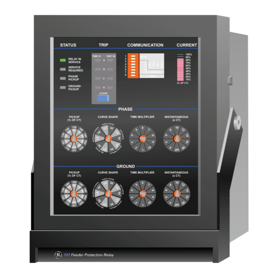
Setup And Operation Front Panel 3.1.1 Description A front panel view of the 735 relay is shown below. An explanation of each of the numbered controls/indicators is contained in the following sections. 735/737 FEEDER PROTECTION RELAY – INSTRUCTION MANUAL 3–1... - Page 34 CHAPTER 3: SETUP AND OPERATION 735 Feed Protection Relay FIGURE 3–1: Front Panel Controls and Indicators 3–2 735/737 FEEDER PROTECTION RELAY – INSTRUCTION MANUAL...
-
Page 35: Controls
For example: CURVE SHAPE: normal inverse PICKUP CURRENT: 480 A PHASE CT RATIO: 600:5 PHASE CURVE SHAPE: normal inverse LO PHASE PICKUP: 80/180 (480 A = 80% of 600 A) 735/737 FEEDER PROTECTION RELAY – INSTRUCTION MANUAL 3–3... -
Page 36: Phase Time Multiplier [3]
Option Switches [14]). Curves are shown in Chapter 5 for overlays and visual inspection. Formulas and tabular data are also given for use with computer software or manual plotting on other co-ordination curves. FIGURE 3–4: Phase Multiplier Time Setting 3–4 735/737 FEEDER PROTECTION RELAY – INSTRUCTION MANUAL... -
Page 37: Phase Instantaneous [4]
(15 to 55%). Use the outer HI band if the ground CURVE SHAPE is set to a HI range (60 to 100%). Select OFF to disable ground time overcurrent pickup and trip. 735/737 FEEDER PROTECTION RELAY – INSTRUCTION MANUAL 3–5... -
Page 38: Ground Curve Shape [6]
For each curve, either the LO band or HI band of the ground pickup setting is selected. See Chapter 5 for actual curves and curve values in table form. FIGURE 3–7: Ground Curve Shape Setting 3–6 735/737 FEEDER PROTECTION RELAY – INSTRUCTION MANUAL... -
Page 39: Ground Time Multiplier [7]
GROUND PICKUP dial setting ranges from 0.1 to 16 times the ground CT rating. For example: PHASE CT RATING: 100:5 (residual ground sensing); GROUND FAULT TRIP: 400 A SETTINGS: Ground Fault Instantaneous = 4 (4 × 100 = 400 A) 735/737 FEEDER PROTECTION RELAY – INSTRUCTION MANUAL 3–7... - Page 40 CHAPTER 3: SETUP AND OPERATION FIGURE 3–9: Ground Instantaneous Trip Setting 3–8 735/737 FEEDER PROTECTION RELAY – INSTRUCTION MANUAL...
-
Page 41: Indicators
Arrangements should be made to check or replace the relay. Phase Pickup When the current in any phase exceeds the PHASE PICKUP control setting, this indicator flashes. If the condition persists, the 735/737 will time out and trip with the TRIP 51-A/B/C indicator on. Ground Pickup... -
Page 42: Phase Current Indicator [12]
PHASE PICKUP: 70% of CT (LO) PHASE CURVE: Normal inverse-LO ACTUAL CURRENT: 165 A DISPLAY: 165/200 = 83% 10% - 80% on 83% > 70% pickup so PHASE PICKUP indicator is flashing 3–10 735/737 FEEDER PROTECTION RELAY – INSTRUCTION MANUAL... -
Page 43: Switches
For example, address 14 = 2 (4 on) + 4 (5 on) + 8 (6 on), with remaining switches 3 (=0) and 7 (=0) off. When switch 8 "TEST" is on, the 735/737 will accept communication commands to simulate different dial settings with computer controlled phase and ground currents for testing and training purposes. - Page 44 The plotted curves falls on normally inverse curve number 4. Select: CURVE SHAPE: Normal Inverse TIME MULTIPLIER: 4 Set the OPTION SWITCHES for a phase overcurrent shift of 1 (switches 1 and 2 both OFF). 3–12 735/737 FEEDER PROTECTION RELAY – INSTRUCTION MANUAL...
- Page 45 PICKUP OR CAUSE OF TRIP: Either pickup or latched cause of trip will energize the relays. This is the same as items 2 and 3 together. 735/737 FEEDER PROTECTION RELAY – INSTRUCTION MANUAL 3–13...
- Page 46 Definite Time BLOCK INSTANTANEOUS ON AUTORECLOSE: Factory Default: Disabled When the 735 is used in conjunction with an autoreclose scheme, it may be desirable to block instantaneous trips after an autoreclosure operation. This prevents nuisance trips due to the normally high inrush currents typically experienced in these situations and allows a coordinated clearance of permanent faults by fuses or inverse-time overcurrent relays.
- Page 47 If GROUND TRIP is enabled the AUX relay will respond only to TIMED or INSTANTANEOUS Ground Faults. Phase O/C Trips will only trip the TRIP relay. Ground Fault Trips will only trip the AUX relay. 735/737 FEEDER PROTECTION RELAY – INSTRUCTION MANUAL 3–15...
-
Page 48: Setup Program
This is useful for obtaining a hardcopy of simulations for later reference. The menus outlined below are used to establish communication with the relay, read/save setpoints to a computer file, configure computer settings and provide product information. FIGURE 3–10: Setup Software System Menus 3–16 735/737 FEEDER PROTECTION RELAY – INSTRUCTION MANUAL... -
Page 49: Communicate
User comments typed with this menu selection will be added to the saved file and printed out on a hardcopy. This is useful for documenting relay types and comments for a specific application. SETPOINTS EDITOR > SETPOINTS > SIMULATED DIALS: 735/737 FEEDER PROTECTION RELAY – INSTRUCTION MANUAL 3–17... -
Page 50: System Configuration
Select the display type that best matches the computer system used. INFO: Product features are displayed in this screen for reference. No operation is performed when this menu item is selected. QUIT: Exit the 735SETUP program back to DOS 3–18 735/737 FEEDER PROTECTION RELAY – INSTRUCTION MANUAL... -
Page 51: Status
After the relay trips, all currents and cause of trip are saved by the relay. This screen shows the information present at time of trip and the cause of trip. Normally this pre-trip information is used when the relay is connected in a communication network to diagnose 735/737 FEEDER PROTECTION RELAY – INSTRUCTION MANUAL 3–19... -
Page 52: Setpoints
Returning the TEST switch 8 to the off position after issuing this command re-enables all trip relays and full protection is restored. COMMANDS > /USE DIAL SETTINGS: 3–20 735/737 FEEDER PROTECTION RELAY – INSTRUCTION MANUAL... -
Page 53: File
RETURN When using a mouse, click on this menu to move cursor up to the next higher menu level. This selection is the same as pressing the ESCAPE key. 735/737 FEEDER PROTECTION RELAY – INSTRUCTION MANUAL 3–21... -
Page 54: Setup Example
Sensor CT The GROUND PICKUP dial is set to 40 (% of CT) which falls on the LO band. Consequently, the selected ground curve shape must be on the LO band setting. 3–22 735/737 FEEDER PROTECTION RELAY – INSTRUCTION MANUAL... - Page 55 10 = 2 (4=on) + 8 (6=on), (3=off, 5=off, 7=off). Disable communications test mode for normal operations (Test 8=off). The switch settings are: Table 3–3: SWITC POSITION SETTING 9600 baud Address 10 Test OFF 735/737 FEEDER PROTECTION RELAY – INSTRUCTION MANUAL 3–23...
- Page 56 CHAPTER 3: SETUP AND OPERATION 3–24 735/737 FEEDER PROTECTION RELAY – INSTRUCTION MANUAL...
-
Page 57: Escription
RS485 hardware. Using RS485, up to 32 slaves can be daisy-chained together on a single communication channel. Due to address limitations only 31 735/737s can be put on a single channel. However, another model of relay could be added, increasing the number to 32. -
Page 58: Data Frame Format And Rate
Data Frame Format and Rate One data frame of an asynchronous transmission to or from a 735/737 consists of 1 start bit, 8 data bits, and 1 stop bit to produce a 10 bit data frame. This is important for transmission through modems at high bit rates (11 bit data frames are not supported by some modems at bit rates of greater than 300 bps). -
Page 59: Timing
If a 735/737 Modbus slave device receives a transmission in which an error is indicated by the CRC-16 calculation, the slave device will not respond to the transmission. A CRC-16... - Page 60 8. is j = 8?No: go to 5. Yes: go to 9. 9. i+1 --> i 10. is i = N? No: go to 3. Yes: go to 11. 11. A --> CRC 4–4 735/737 FEEDER PROTECTION RELAY – INSTRUCTION MANUAL...
-
Page 61: Supported Modbus Functions
CHAPTER 4: MODBUS COMMUNICATIONS Supported Modbus Functions 4.2.1 Description The following functions are supported by the 735/737: • 03: Read Setpoints • 04:Read Actual Values • 05: Execute Operation • 06: Store Single Setpoint (test/simulation) • 07: Read Device Status •... -
Page 62: Function Code 04: Read Actual Values
The maximum number of actual values that can be read in one transmission is 60 in the 735/737. The slave response to this function code is the slave address, function code, a count of the number of data bytes to follow, the data itself, and the CRC. -
Page 63: Function Code 05: Execute Operation
Function Code 05: Execute Operation Modbus Implementation: Force Single Coil 735/737 Implementation: Execute Operation This function code allows the master to request the 735/737 to perform specific operations. The operations that can be performed by the 735/737 are as follows: Table 4–4:... -
Page 64: Function Code 06: Store Single Setpoint
SLAVE ADDRESS message for slave 11 FUNCTION CODE store single setpoint DATA STARTING ADDRESS 00 49 setpoint address 0049h DATA 03 9E data for address 0049h ?? ?? CRC calculated by the master 4–8 735/737 FEEDER PROTECTION RELAY – INSTRUCTION MANUAL... -
Page 65: Function Code 07: Read Status
CODE VALUE status = 001101101 (binary) ?? ?? CRC calculated by the slave 4.2.7 Function Code 16: Store Multiple Setpoints Modbus Implementation: Preset Multiple Registers 735/737 Implementation: Store Multiple Setpoints 735/737 FEEDER PROTECTION RELAY – INSTRUCTION MANUAL 4–9... - Page 66 Modbus “registers” are 16 bit (two byte) values transmitted high order byte first. Thus all 735/737 setpoints are sent as two bytes. The slave device response to this function code is to echo the slave address, function code, starting address, the number of setpoints loaded, and the CRC.
- Page 67 NUMBER OF SETPOINTS 00 0A 10 setpoints (2 bytes each) ?? ?? CRC calculated by the slave For 16 bit transfers hi byte is transmitted first. For example, 0050h is transmitted 00h then Note 735/737 FEEDER PROTECTION RELAY – INSTRUCTION MANUAL 4–11...
-
Page 68: Error Responses
4.2.8 Error Responses When a 735/737 detects an error other than a CRC error, a response will be sent to the master. The most significant bit of the FUNCTION CODE byte will be set to 1 (that is, the function code sent from the slave will be equal to the function code sent from the master plus 128). -
Page 69: 4.3 Memory Map
4.3.1 Modbus Memory Map The data stored in the 735/737 is grouped as actual values and setpoints. Setpoints can be read and written by a master computer. Actual values can only be read. All setpoints and actual values are stored as two byte values. That is, each address listed in the memory map is the address of a two byte value. - Page 70 CHAPTER 4: MODBUS COMMUNICATIONS Table 4–10: 735/737 MODBUS MEMORY MAP (Sheet 2 of 4) GROUP DESCRIPTION RANGE UNITS FORMAT FACTORY DEFAULT PRE-TRIP DATA 0020 Phase A pre-trip current 0 to 2000 % CT 0021 Phase B pre-trip current 0 - 2000...
- Page 71 CHAPTER 4: MODBUS COMMUNICATIONS Table 4–10: 735/737 MODBUS MEMORY MAP (Sheet 3 of 4) GROUP DESCRIPTION RANGE UNITS FORMAT FACTORY DEFAULT 005B Ground current (Simulation) 0 to 2000 % CT 005C Output relays (Test - I/O) Bits F103 005D LED (Test - I/O)
-
Page 72: Memory Map Data Formats
↓ ↓ ↓ ↓ ↓ 006F Not used 4.3.2 Memory Map Data Formats Table 4–11: 735/737 MEMORY MAP DATA FORMATS (Sheet 1 of 6) FORMA TYPE DESCRIPTION UNSIGNED INTEGER 0 to 65535 UNSIGNED INTEGER 0 to 6553.5 1 DECIMAL PLACE... - Page 73 CHAPTER 4: MODBUS COMMUNICATIONS Table 4–11: 735/737 MEMORY MAP DATA FORMATS (Sheet 2 of 6) FORMA TYPE DESCRIPTION F102 DIP Switches XXXX XXXX XXXX XXX1 = Switch 1 on=1 XXXX XXXX XXXX XX1X = Switch 2 on = 1 XXXX XXXX XXXX X1XX = Switch 3 on = 1...
- Page 74 CHAPTER 4: MODBUS COMMUNICATIONS Table 4–11: 735/737 MEMORY MAP DATA FORMATS (Sheet 3 of 6) FORMA TYPE DESCRIPTION XXXX XXXX XXXX XXX1 = Phase A overcurrent LED on = 1 LEDs F105 (READ ONLY) XXXX XXXX XXXX XX1X = Phase B overcurrent LED on = 1...
- Page 75 CHAPTER 4: MODBUS COMMUNICATIONS Table 4–11: 735/737 MEMORY MAP DATA FORMATS (Sheet 4 of 6) FORMA TYPE DESCRIPTION OFF = 1 F108 PHASE PICKUP SWITCH 20 = 2 30 = 3 40 = 4 50 = 5 60 = 6...
- Page 76 CHAPTER 4: MODBUS COMMUNICATIONS Table 4–11: 735/737 MEMORY MAP DATA FORMATS (Sheet 5 of 6) FORMA TYPE DESCRIPTION F110 60 = 11 ctd. 65 = 12 70 = 13 75 = 14 80 = 15 85 = 16 90 = 17...
- Page 77 CHAPTER 4: MODBUS COMMUNICATIONS Table 4–11: 735/737 MEMORY MAP DATA FORMATS (Sheet 6 of 6) FORMA TYPE DESCRIPTION 7 = 7 8 = 8 9 = 9 10 = 10 F113 CAUSE OF TRIP XXXX XXXX XXXX XXX1 = Phase A time OC trip...
- Page 78 CHAPTER 4: MODBUS COMMUNICATIONS 4–22 735/737 FEEDER PROTECTION RELAY – INSTRUCTION MANUAL...
-
Page 79: Escription
• IAC Very Inverse • IAC Extremely Inverse • Definite Time IEC/BS142 CURVES • IEC Short Time • IEC A (Normal Inverse) • IEC B (Very Inverse) • IEC C (Extremely Inverse) • Definite Time 735/737 FEEDER PROTECTION RELAY – INSTRUCTION MANUAL 5–1... - Page 80 For the graphs shown in this chapter, the per unit value (on the x-axis) is given as: --- - Per Unit ------------------------------------- - ⁄ × where: I = current input to relay = pickup current setpoint CT = CT secondary, that is1 or 5 A 5–2 735/737 FEEDER PROTECTION RELAY – INSTRUCTION MANUAL...
-
Page 81: Ansi Curves
1.126 1.066 1.021 0.986 0.884 0.835 43.849 6.079 3.408 2.149 1.718 1.496 1.359 1.267 1.200 1.149 1.109 0.994 0.939 48.722 6.755 3.787 2.388 1.909 1.662 1.510 1.407 1.333 1.277 1.233 1.105 1.043 735/737 FEEDER PROTECTION RELAY – INSTRUCTION MANUAL 5–3... - Page 82 2.477 2.346 2.247 2.169 1.945 1.836 96.469 13.374 7.498 4.728 3.780 3.290 2.990 2.787 2.640 2.528 2.441 2.188 2.066 107.187 14.860 8.332 5.253 4.200 3.656 3.322 3.096 2.933 2.809 2.712 2.431 2.295 5–4 735/737 FEEDER PROTECTION RELAY – INSTRUCTION MANUAL...
- Page 83 CHAPTER 5: OVERCURRENT CURVES 735/737 ANSI MODERATELY INVERSE CURVES GE POWER MANAGEMENT 1000 TIME MULTIPLIER 0.01 0.01 803658A4.CDR MULTIPLE OF PICKUP CURRENT (PER UNIT) FIGURE 5–1: ANSI Moderately Inverse Curves 735/737 FEEDER PROTECTION RELAY – INSTRUCTION MANUAL 5–5...
-
Page 84: Ansi Normal Inverse Curves
1.208 1.082 0.983 0.904 0.659 0.530 77.529 19.279 7.945 3.392 2.307 1.830 1.550 1.359 1.217 1.106 1.017 0.741 0.596 86.143 21.421 8.828 3.769 2.563 2.034 1.722 1.509 1.352 1.229 1.130 0.823 0.663 5–6 735/737 FEEDER PROTECTION RELAY – INSTRUCTION MANUAL... - Page 85 2.657 2.379 2.163 1.989 1.449 1.166 170.564 42.413 17.479 7.463 5.076 4.027 3.410 2.989 2.677 2.433 2.237 1.630 1.312 189.515 47.125 19.421 8.293 5.640 4.474 3.789 3.321 2.974 2.704 2.486 1.812 1.458 735/737 FEEDER PROTECTION RELAY – INSTRUCTION MANUAL 5–7...
- Page 86 CHAPTER 5: OVERCURRENT CURVES 735/737 ANSI NORMAL INVERSE CURVE GE POWER MANAGEMENT 1000 TIME MULTIPLIER 0.01 0.01 803662A4.CDR MULTIPLE OF PICKUP CURRENT (PER UNIT) FIGURE 5–2: ANSI Normal Inverse Curves 5–8 735/737 FEEDER PROTECTION RELAY – INSTRUCTION MANUAL...
-
Page 87: Ansi Very Inverse Curves
0.755 0.680 0.625 0.583 0.464 0.408 53.732 14.104 5.963 2.416 1.535 1.169 0.973 0.849 0.765 0.703 0.655 0.522 0.459 59.702 15.671 6.626 2.685 1.706 1.299 1.081 0.944 0.850 0.781 0.728 0.580 0.510 735/737 FEEDER PROTECTION RELAY – INSTRUCTION MANUAL 5–9... - Page 88 1.661 1.496 1.375 1.282 1.020 0.897 118.210 31.028 13.119 5.315 3.378 2.573 2.140 1.869 1.683 1.546 1.442 1.148 1.009 131.344 34.475 14.577 5.906 3.753 2.859 2.377 2.076 1.870 1.718 1.602 1.276 1.121 5–10 735/737 FEEDER PROTECTION RELAY – INSTRUCTION MANUAL...
- Page 89 CHAPTER 5: OVERCURRENT CURVES 735/737 ANSI VERY INVERSE CURVE GE POWER MANAGEMENT 1000 TIME MULTIPLIER 0.01 0.01 803660A4.CDR MULTIPLE OF PICKUP CURRENT (PER UNIT) FIGURE 5–3: ANSI Very Inverse Curves 735/737 FEEDER PROTECTION RELAY – INSTRUCTION MANUAL 5–11...
-
Page 90: Ansi Extremely Inverse Curves
0.596 0.503 0.439 0.393 0.281 0.239 66.358 18.004 7.849 2.967 1.656 1.113 0.834 0.671 0.566 0.494 0.442 0.316 0.269 73.731 20.005 8.722 3.297 1.840 1.237 0.927 0.745 0.628 0.549 0.491 0.351 0.298 5–12 735/737 FEEDER PROTECTION RELAY – INSTRUCTION MANUAL... - Page 91 1.312 1.106 0.966 0.864 0.618 0.525 145.988 39.609 17.269 6.528 3.643 2.449 1.836 1.476 1.244 1.086 0.973 0.696 0.591 162.208 44.010 19.188 7.253 4.047 2.722 2.040 1.640 1.383 1.207 1.081 0.773 0.656 735/737 FEEDER PROTECTION RELAY – INSTRUCTION MANUAL 5–13...
- Page 92 CHAPTER 5: OVERCURRENT CURVES 735/737 ANSI EXTREMELY INVERSE CURVE GE POWER MANAGEMENT 1000 TIME MULTIPLIER 0.01 0.01 MULTIPLE OF PICKUP CURRENT (PER UNIT) 803661A4.CDR FIGURE 5–4: Ansi Extremely Inverse Curves 5–14 735/737 FEEDER PROTECTION RELAY – INSTRUCTION MANUAL...
- Page 93 0.400 0.400 0.400 0.400 0.400 0.400 0.450 0.450 0.450 0.450 0.450 0.450 0.450 0.450 0.450 0.450 0.450 0.450 0.450 0.500 0.500 0.500 0.500 0.500 0.500 0.500 0.500 0.500 0.500 0.500 0.500 0.500 735/737 FEEDER PROTECTION RELAY – INSTRUCTION MANUAL 5–15...
- Page 94 0.880 0.880 0.880 0.880 0.880 0.880 0.990 0.990 0.990 0.990 0.990 0.990 0.990 0.990 0.990 0.990 0.990 0.990 0.990 1.100 1.100 1.100 1.100 1.100 1.100 1.100 1.100 1.100 1.100 1.100 1.100 1.100 5–16 735/737 FEEDER PROTECTION RELAY – INSTRUCTION MANUAL...
-
Page 95: Definite Time Curves
CHAPTER 5: OVERCURRENT CURVES 735/737 DEFINITE TIME CURVES GE POWER MANAGEMENT 1000 TIME MULTIPLIER 0.01 0.01 803650A4.CDR MULTIPLE OF PICKUP CURRENT (PER UNIT) FIGURE 5–5: Definite Time Curves 735/737 FEEDER PROTECTION RELAY – INSTRUCTION MANUAL 5–17... -
Page 96: Iac Curves
0.210 0.204 0.200 0.197 0.188 0.184 2.056 0.644 0.427 0.314 0.276 0.256 0.244 0.236 0.230 0.225 0.222 0.212 0.207 2.285 0.716 0.474 0.349 0.307 0.285 0.271 0.262 0.255 0.250 0.247 0.235 0.230 5–18 735/737 FEEDER PROTECTION RELAY – INSTRUCTION MANUAL... - Page 97 0.461 0.450 0.441 0.434 0.414 0.404 4.524 1.417 0.939 0.692 0.607 0.563 0.537 0.519 0.506 0.496 0.488 0.466 0.455 5.027 1.575 1.043 0.768 0.674 0.626 0.596 0.576 0.562 0.551 0.542 0.517 0.505 735/737 FEEDER PROTECTION RELAY – INSTRUCTION MANUAL 5–19...
- Page 98 CHAPTER 5: OVERCURRENT CURVES 735/737 IAC SHORT INVERSE CURVE GE POWER MANAGEMENT CURVE MULTIPLIER 0.01 803655A4.CDR MULTIPLE OF PICKUP CURRENT (PER UNIT) FIGURE 5–6: IAC Short Inverse Curves 5–20 735/737 FEEDER PROTECTION RELAY – INSTRUCTION MANUAL...
-
Page 99: Iac Inverse Curves
1.348 1.280 1.229 1.188 1.066 1.007 42.447 5.199 3.372 2.394 1.992 1.765 1.619 1.516 1.441 1.382 1.336 1.200 1.132 47.163 5.776 3.747 2.660 2.213 1.961 1.798 1.685 1.601 1.536 1.485 1.333 1.258 735/737 FEEDER PROTECTION RELAY – INSTRUCTION MANUAL 5–21... - Page 100 2.965 2.817 2.703 2.613 2.346 2.214 93.383 11.437 7.419 5.267 4.382 3.883 3.561 3.336 3.169 3.041 2.939 2.639 2.491 103.759 12.708 8.243 5.852 4.869 4.314 3.957 3.706 3.521 3.379 3.266 2.932 2.768 5–22 735/737 FEEDER PROTECTION RELAY – INSTRUCTION MANUAL...
- Page 101 CHAPTER 5: OVERCURRENT CURVES 735/737 IAC GE POWER MANAGEMENT INVERSE CURVE 1000 CURVE MULTIPLIER CURVE MULTIPLIER 803659A4.CDR MULTIPLE OF PICKUP CURRENT (PER UNIT) FIGURE 5–7: IAC Inverse Curves 735/737 FEEDER PROTECTION RELAY – INSTRUCTION MANUAL 5–23...
-
Page 102: Iac Very Inverse Curves
0.810 0.745 0.698 0.662 0.560 0.511 39.520 13.055 5.904 2.418 1.545 1.198 1.020 0.911 0.838 0.785 0.744 0.630 0.575 43.911 14.506 6.560 2.687 1.717 1.332 1.133 1.012 0.931 0.872 0.827 0.700 0.639 5–24 735/737 FEEDER PROTECTION RELAY – INSTRUCTION MANUAL... - Page 103 1.782 1.638 1.535 1.456 1.232 1.124 86.944 28.722 12.990 5.320 3.400 2.637 2.243 2.004 1.843 1.727 1.638 1.386 1.265 96.604 31.913 14.433 5.912 3.778 2.930 2.492 2.227 2.048 1.918 1.820 1.540 1.405 735/737 FEEDER PROTECTION RELAY – INSTRUCTION MANUAL 5–25...
- Page 104 CHAPTER 5: OVERCURRENT CURVES 735/737 IAC VERY INVERSE CURVE GE POWER MANAGEMENT 1000 CURVE MULTIPLIER 803657A4.CDR MULTIPLE OF PICKUP CURRENT (PER UNIT) FIGURE 5–8: IAC Very Inverse Curves 5–26 735/737 FEEDER PROTECTION RELAY – INSTRUCTION MANUAL...
-
Page 105: Iac Extremely Inverse Curves
0.595 0.495 0.424 0.370 0.228 0.167 64.119 15.290 6.743 2.726 1.600 1.106 0.837 0.670 0.557 0.477 0.417 0.257 0.188 71.243 16.989 7.492 3.029 1.778 1.229 0.929 0.744 0.619 0.530 0.463 0.285 0.209 735/737 FEEDER PROTECTION RELAY – INSTRUCTION MANUAL 5–27... - Page 106 1.310 1.090 0.933 0.815 0.502 0.367 141.061 33.639 14.834 5.997 3.520 2.433 1.840 1.474 1.226 1.049 0.917 0.565 0.413 156.734 37.377 16.482 6.664 3.911 2.703 2.045 1.637 1.362 1.166 1.019 0.628 0.459 5–28 735/737 FEEDER PROTECTION RELAY – INSTRUCTION MANUAL...
- Page 107 CHAPTER 5: OVERCURRENT CURVES 735/737 IAC EXTREMELY INVERSE CURVE GE POWER MANAGEMENT 1000 CURVE MULTIPLIER 0.01 803656A4.CDR MULTIPLE OF PICKUP CURRENT (PER UNIT) FIGURE 5–9: IAC Extremely Inverse Curves 735/737 FEEDER PROTECTION RELAY – INSTRUCTION MANUAL 5–29...
-
Page 108: Iec Curves
0.246 0.230 0.217 0.206 0.175 0.159 11.522 1.376 0.801 0.503 0.396 0.339 0.303 0.277 0.258 0.244 0.232 0.197 0.179 12.802 1.528 0.890 0.559 0.440 0.377 0.336 0.308 0.287 0.271 0.258 0.219 0.199 5–30 735/737 FEEDER PROTECTION RELAY – INSTRUCTION MANUAL... - Page 109 0.542 0.505 0.476 0.454 0.385 0.350 25.348 3.026 1.762 1.106 0.871 0.745 0.666 0.610 0.568 0.536 0.510 0.433 0.394 28.165 3.362 1.958 1.229 0.968 0.828 0.739 0.677 0.631 0.595 0.567 0.481 0.437 735/737 FEEDER PROTECTION RELAY – INSTRUCTION MANUAL 5–31...
- Page 110 CHAPTER 5: OVERCURRENT CURVES 735/737 IEC SHORT TIME CURVE GE POWER MANAGEMENT 1000 CURVE MULTIPLIER FACEPLATE EQUIVALENT 803654A4.CDR MULTIPLE OF PICKUP CURRENT (PER UNIT) FIGURE 5–10: IEC Short Time Curves 5–32 735/737 FEEDER PROTECTION RELAY – INSTRUCTION MANUAL...
-
Page 111: Iec A Curves
1.404 1.310 1.237 1.179 1.003 0.914 64.530 7.729 4.510 2.842 2.245 1.925 1.722 1.580 1.474 1.392 1.326 1.128 1.028 71.700 8.588 5.011 3.158 2.495 2.139 1.913 1.755 1.638 1.546 1.473 1.253 1.142 735/737 FEEDER PROTECTION RELAY – INSTRUCTION MANUAL 5–33... - Page 112 3.089 2.882 2.721 2.593 2.206 2.010 141.966 17.004 9.922 6.252 4.939 4.236 3.789 3.475 3.242 3.062 2.917 2.482 2.262 157.740 18.893 11.024 6.947 5.488 4.707 4.209 3.861 3.603 3.402 3.241 2.758 2.513 5–34 735/737 FEEDER PROTECTION RELAY – INSTRUCTION MANUAL...
- Page 113 CHAPTER 5: OVERCURRENT CURVES 735/737 IEC-A CURVE (NORMAL INVERSE) GE POWER MANAGEMENT 1000 CURVE MULTIPLIER FACEPLATE EQUIVALENT 803653A4.CDR MULTIPLE OF PICKUP CURRENT (PER UNIT) FIGURE 5–11: IEC A Curves 735/737 FEEDER PROTECTION RELAY – INSTRUCTION MANUAL 5–35...
-
Page 114: Iec B Curves
0.898 0.770 0.674 0.599 0.386 0.285 121.500 12.152 6.076 3.036 2.023 1.516 1.213 1.010 0.866 0.758 0.674 0.434 0.321 135.000 13.502 6.751 3.374 2.247 1.685 1.347 1.123 0.962 0.842 0.749 0.482 0.356 5–36 735/737 FEEDER PROTECTION RELAY – INSTRUCTION MANUAL... - Page 115 1.976 1.694 1.482 1.318 0.849 0.627 267.309 26.734 13.368 6.680 4.450 3.336 2.668 2.223 1.905 1.667 1.482 0.955 0.705 297.010 29.704 14.853 7.422 4.944 3.706 2.964 2.470 2.117 1.853 1.647 1.061 0.784 735/737 FEEDER PROTECTION RELAY – INSTRUCTION MANUAL 5–37...
- Page 116 CHAPTER 5: OVERCURRENT CURVES 735/737 IEC-B CURVE (VERY INVERSE) GE POWER MANAGEMENT 1000 CURVE MULTIPLIER FACEPLATE EQUIVALENT 0.01 803652A4.CDR MULTIPLE OF PICKUP CURRENT (PER UNIT) FIGURE 5–12: IEC B Curves 5–38 735/737 FEEDER PROTECTION RELAY – INSTRUCTION MANUAL...
-
Page 117: Iec C Curves
0.666 0.508 0.400 0.323 0.144 0.082 351.216 28.801 12.001 4.500 2.399 1.499 1.028 0.749 0.571 0.450 0.364 0.162 0.092 390.240 32.001 13.335 5.000 2.666 1.665 1.142 0.833 0.634 0.500 0.404 0.180 0.102 735/737 FEEDER PROTECTION RELAY – INSTRUCTION MANUAL 5–39... - Page 118 1.465 1.117 0.880 0.711 0.316 0.180 772.686 63.362 26.402 9.899 5.278 3.298 2.261 1.648 1.256 0.990 0.800 0.356 0.202 858.540 70.402 29.336 10.999 5.864 3.664 2.512 1.832 1.396 1.100 0.889 0.396 0.225 5–40 735/737 FEEDER PROTECTION RELAY – INSTRUCTION MANUAL...
- Page 119 CHAPTER 5: OVERCURRENT CURVES 735/737 IEC-C CURVE (EXTREMELY INVERSE) GE POWER MANAGEMENT 1000 CURVE MULTIPLIER FACEPLATE EQUIVALENT 0.01 803651A4.CDR MULTIPLE OF PICKUP CURRENT (PER UNIT) FIGURE 5–13: IEC C Curves 735/737 FEEDER PROTECTION RELAY – INSTRUCTION MANUAL 5–41...
- Page 120 CHAPTER 5: OVERCURRENT CURVES 5–42 735/737 FEEDER PROTECTION RELAY – INSTRUCTION MANUAL...
-
Page 121: Primary Injection Testing
A PC equipped with an RS232/RS485 convertor and the Setup program can be used to establish communications with the 735 or 737. See Sections 2.2.4 Communications and 3.5 Setup Program. With the use of the setup program or Relaycom, custom scheme setpoints can be set and tested and the actual values screens can be used to monitor metered data and pre-trip data. -
Page 122: Phase Current Reading Accuracy Test
6.1.4 Phase Current Reading Accuracy Test The 735/737 relay must read the phase current signals input from the CTs correctly to provide the instantaneous and timed overcurrent protection. To determine if the relay is reading correctly set the phase pickup dial to 100% of the CT primary. Use the 3 Phase Test Set to set the phase current injected into the phases. -
Page 123: Instantaneous Phase Overcurrent Timing Test
The timer on the 3-phase Test Set should be setup to start when current is injected and stop when the trip or auxiliary (if assigned) relay activates. Verify that the INST 50 phase A, B, or C (whichever phase tested) LED has been activated and latched. 735/737 FEEDER PROTECTION RELAY – INSTRUCTION MANUAL 6–3... -
Page 124: Instantaneous Ground Fault Overcurrent Timing Test
LEDs turn off. Now power up the relay. The relay should turn on and the service relay change state at or before the specified power supply range. The trip LED should again be illuminated. 6–4 735/737 FEEDER PROTECTION RELAY – INSTRUCTION MANUAL... -
Page 125: 6.1.13 Hi Potential Test
All remaining terminals except safety ground (G12) should be connected together and the test performed with respect to safety ground. Make sure to disconnect the filter ground (G11) before performing this test. Refer to Section 2.2.7: Hi-pot Testing for more information. 735/737 FEEDER PROTECTION RELAY – INSTRUCTION MANUAL 6–5... -
Page 126: Test Records
(%CT) (%CT) PHASE 1 CURRENT LOW END PHASE 1 CURRENT HIGH END PHASE 2 CURRENT LOW END PHASE 2 CURRENT HIGH END PHASE 3 CURRENT LOW END PHASE 3 CURRENT HIGH END 6–6 735/737 FEEDER PROTECTION RELAY – INSTRUCTION MANUAL... -
Page 127: Ground Current Reading Accuracy Test
PHASE 3 / LOW END PHASE 3 / HIGH END 6.2.6 Instantaneous Ground Overcurrent Pickup Test Table 6–6: PHASE AND LEVEL DIAL SETTING INPUT CURRENT STATUS (xCT) GROUND / LOW END GROUND / HIGH END 735/737 FEEDER PROTECTION RELAY – INSTRUCTION MANUAL 6–7... -
Page 128: Instantaneous Phase Overcurrent Timing Test
GROUND / LOW END ≤ 35 GROUND / HIGH END 6.2.9 Phase Overcurrent Curve Verification Table 6–9: PICKUP CURVE TIME TIME INPUT EXPECTED MEASURED STATUS LEVEL SHAPE MULT SHIFT CURRENT ( ) TIME TIME 6–8 735/737 FEEDER PROTECTION RELAY – INSTRUCTION MANUAL... -
Page 129: 6.2.10 Ground Fault Overcurrent Curve Verification
6.2.12 Hi Potential Test Note the Filter Ground (terminal G11) must be left floating for this test. See Section 2.2.7: Hi-pot Testing for details. Table 6–12: HIPOT LEVEL (kV) DURATION ( STATUS 735/737 FEEDER PROTECTION RELAY – INSTRUCTION MANUAL 6–9... - Page 130 CHAPTER 6: TESTING 6–10 735/737 FEEDER PROTECTION RELAY – INSTRUCTION MANUAL...
-
Page 131: Installation Information
Phase Instantaneous Dial (OFF, 4, 5, 6, 8, 10, 12, 14, 16, 20 x CT) GROUND DIAL SETTINGS Ground Pickup Dial (LO: 15 to 55% of CT; HI: 60 to 100% of CT; OFF) 735/737 FEEDER PROTECTION RELAY – INSTRUCTION MANUAL 7–1... - Page 132 Custom Scheme > Time Overcurrent Curve Shape (ANSI, IAC, BS142) Custom Scheme > Block Instantaneous on Autoreclose (Disabled, Enabled) Custom Scheme > Aux Trip Relay (Main Trip, 86 Lockout, Ground Trip) COMMUNICATIONS SETTINGS Baud Rate Communications Address 7–2 735/737 FEEDER PROTECTION RELAY – INSTRUCTION MANUAL...
-
Page 133: Characteristics
(normally between 0.2 and 0.5 seconds). Also obtain appropriate curve shape and time multiplier from coordination curves. In this case, ‘very inverse’ and 2 times, respectively. • Phase Curve Shape dial setting = VERY INVERSE (HI); Phase Time Multiplier dial setting = 2 735/737 FEEDER PROTECTION RELAY – INSTRUCTION MANUAL A–1... -
Page 134: Phase Instantaneous Pickup
• Level for ground instantaneous element = 2400 A primary • Secondary ground instantaneous level = 2400 A × (5 / 600) = 20 A • Ground Instantaneous dial setting = 20 A / 5 A = 4 A–2 735/737 FEEDER PROTECTION RELAY – INSTRUCTION MANUAL... -
Page 135: Feeder Dedicated To A Transformer
Instead set instantaneous pickup at 120% of inrush level. Instantaneous pickup current level = 1.2 × 1255 = 1506 A Phase Instantaneous dial setting = 1506 A / 150 A ≈ 10 735/737 FEEDER PROTECTION RELAY – INSTRUCTION MANUAL A–3... -
Page 136: Dos And Don'ts
The 735/737 can provide for direct or remote communication (via a modem). An RS232 to RS485 converter is used to tie it to a PC/PLC or DCS system. The 735/737 supports Modbus RTU protocol functions 03, 04, 05, 06, 07, and 16. For more information refer to Chapter 4: COMMUNICATIONS. - Page 137 – terminal to other devices A or – terminals. Ground CTs It should be noted that the 735/737 does not accept the GE Multilin 2000:1 CT which is actually a 50:0.025 CT. Only CTs with 5 A or 1 A secondaries may be used...
-
Page 138: Revision History
07/20/2006 1601-0048-DH 25D156D1.000 02/09/2008 1601-0048-DJ 25D156D1.000 04/02/2008 1601-0048-DK 25D156D1.000 05/31/2010 A.4.2 Changes to the Manual Table A–1: Major Updates for 735 Revision DK PAGE SECT CHANGE DESCRIPTION (DJ) (DK) Title Title Update Manual part number to 1601-0048-DK Table 3-1 Correction Corrections to Pickup section Table A–2: Major Updates for 735 Revision DJ... - Page 139 A: APPENDIX A.4 REVISION HISTORY Table A–3: Major Updates for 735 Revision DH PAGE SECT CHANGE DESCRIPTION (DG) (DH) Title Title Update Manual part number to 1601-0048-DH General Update Minor structural updates 735/737 FEEDER PROTECTION RELAY – INSTRUCTION MANUAL A–7...
-
Page 140: Warranty Information
For complete text of Warranty (including limitations and disclaimers), refer to GE Multilin Standard Conditions of Sale. A–8 735/737 FEEDER PROTECTION RELAY – INSTRUCTION MANUAL... - Page 141 ....................7-1 COMMUNICATIONS description ....................... 2-10 electrical interface ................... 4-1 errors ....................... 4-12 memory map ....................4-13 multi-channel relaying ..................2-13 overview ......................4-1 RS485 ...................... 2-11, 2-12 slave address ....................4-2 735/737 FEEDER PROTECTION RELAY – INSTRUCTION MANUAL I–1...
- Page 142 ................2-6 ENABLE TRIP RELAYS ..................3-20 ENVIRONMENTAL SPECIFICATIONS ..............1-9 ERROR CHECKING ..................... 4-3 ERROR RESPONSES ..................4-12 FEATURES ......................1-1 FILE MENU ......................3-21 FREQUENCY ...................... 3-13 FRONT PANEL ....................3-1 I–2 735/737 FEEDER PROTECTION RELAY – INSTRUCTION MANUAL...
- Page 143 ILLEGAL DATA ADDRESS ERROR ..............4-12 ILLEGAL DATA VALUE ERROR ................. 4-12 INDICATORS ................1-1, 1-9, 3-9, 3-10 INPUTS specifications ....................1-7 INSERTION ......................2-4 INSTALLATION electrical ......................2-6 mechanical ....................... 2-1 wiring ........................ 2-6 735/737 FEEDER PROTECTION RELAY – INSTRUCTION MANUAL I–3...
- Page 144 PHASE TIME, GROUND TIME, PHASE INSTANTANEOUS, and GROUND INSTANTANEOUS OVERCURRENT OVERCURRENT CURVES ..................5-1 PANEL CUTOUTS ....................2-2 PHASE INSTANTANEOUS OVERCURRENT curve shape ....................3-3, 3-4 level ........................3-5 multiplier ......................3-4 I–4 735/737 FEEDER PROTECTION RELAY – INSTRUCTION MANUAL...
- Page 145 SETTINGS TABLE ....................7-1 SETUP PROGRAM ..................... 3-16 SIMULATE CURRENTS ..................3-21 SIMULATE DIALS ....................3-21 SLAVE ADDRESS ....................4-2 SOFTWARE actual values ..................3-19, 3-20 commands ....................... 3-20 setpoints ......................3-20 735/737 FEEDER PROTECTION RELAY – INSTRUCTION MANUAL I–5...
- Page 146 TRIP RECORD, PRINTING ................. 3-21 TRIP RELAYS, DISABLING ................3-20 TRIP RELAYS, ENABLING ................. 3-20 TYPE TESTS ....................... 1-10 TYPICAL WIRING DIAGRAM ................2-7 WARRANTY ......................A-8 WIRING DIAGRAM ....................2-7 WITHDRAWAL ....................2-3 I–6 735/737 FEEDER PROTECTION RELAY – INSTRUCTION MANUAL...
Need help?
Do you have a question about the 735 and is the answer not in the manual?
Questions and answers
What can cause the SR735 relay to blink red?
The GE Digital Energy SR735 relay blinks red when the Phase Pickup or Ground Pickup indicators are active.
- Phase Pickup Blinking: Occurs when the current in any phase exceeds the PHASE PICKUP control setting. If the condition persists, the relay will time out and trip.
- Ground Pickup Blinking: Occurs when ground (neutral) current exceeds the GROUND PICKUP control setting. If this overcurrent persists, the relay will time out and trip.
In both cases, if the fault continues, the relay will trip, and the corresponding TRIP 51-A/B/C (for phase faults) or TRIP 51-N (for ground faults) indicator will turn on.
This answer is automatically generated