ACU-RITE MILLPWR G2 Technical Manual
Hide thumbs
Also See for MILLPWR G2:
- User manual (244 pages) ,
- Software update (7 pages) ,
- Software update (7 pages)
Table of Contents
Advertisement
Quick Links
Download this manual
See also:
User Manual
Advertisement
Table of Contents

Related Manuals for ACU-RITE MILLPWR G2


Summary of Contents for ACU-RITE MILLPWR G2
- Page 1 MILLPWR ACU-RITE ® Technical Manual...
-
Page 3: Table Of Contents
Table of Contents Update Information General Information ................13 Introduction Meaning of the Symbols Used in this Manual ........15 Proper Operation.................15 Trained Personnel ................15 Grounding, and Connections...............15 General Information ................16 Overview of Components ..............17 2.6.1 MILLPWR Control ..............17 2.6.2 Keys on visual display unit .............18 Power control keys............18 Data Entry keys ..............18 Function keys ..............18... - Page 4 3.10.3 USB Hub ................58 3.10.4 Touch Probe Systems............59 Adapter cable for TS ............59 TS 220 ................60 Adapter cable for TS 120/TS 220........60 SE 640 transmitter-receiver unit........61 SE 540 transmitter-receiver unit........62 TS 440 ................63 TS 640 ................63 ACU-RITE Technical Manual MILLPWR...
- Page 5 Machine Parameters General Information ................65 Managing Parameters .................67 4.2.1 Entering and Editing Machine Parameters......67 Icons in the object tree ............68 Displaying help texts............70 Entering and editing parameters ........71 Limit values ..............71 Copy/Paste value function in ConfigEditor .......71 Deleting objects..............71 Inserting and copying objects...........71 Changing key names ............72 Saving input values............72 Find function..............73...
- Page 6 Encoder Monitoring .............274 Position encoder.............274 Analog Axes ..................276 Analog output ..............276 Rapid traverse for analog axes ........277 Reading Axis Information ..............278 Reading the axis coordinates..........279 Traverse Ranges ................280 Controlling Axes by PLC..............281 Positioning of axes by PLC ..........281 ACU-RITE Technical Manual MILLPWR...
- Page 7 5.10 Axis Error Compensation ..............284 5.10.1 Backlash Compensation............285 5.10.2 Linear Axis Error Compensation ..........287 5.10.3 Nonlinear Axis Error Compensation ........289 Compensation value tables ..........291 Entering compensation values ........292 Importing data from calibration software: ......293 Assigning the compensation value tables to the axes...293 Activate error compensation ..........294 5.10.4 Compensation of Thermal Expansion ........297 5.11 Machine Kinematics................299...
- Page 8 ..............383 5.15.3 Record Signals ..............384 Starting and stopping the recording .......384 Trigger conditions ............385 5.15.4 Analyze Recording ...............386 Recording completed...............386 Changing the display............387 Analyze an individual analog signal ........387 Influence the signal display..........387 Second cursor..............388 ACU-RITE Technical Manual MILLPWR...
- Page 9 5.15.5 Saving and Loading Recordings ...........388 5.15.6 Configure the Colors of the Oscilloscope Display....389 Machine Integration Software Version................393 Display and Operation ...............394 6.2.1 Position and Status Display..........394 6.2.2 Unit of Measurement for Display and Operation ....395 6.2.3 Decimal Separator..............395 Switching the Control On/Off............397 6.3.1 Powering Up the Control .............397 Message for power interruption........397...
- Page 10 Actual status 1 of the axes (Ipo Act State 1) ....484 Actual status 2 of the axes (Ipo Act State 2) ....486 Deleting the following error (Clear PeakLag) ....488 Deleting the reference point (Clear RefOk) ....488 ACU-RITE Technical Manual MILLPWR...
- Page 11 6.12.6 Group of NC Channels ............489 Data of the interpolator module (Ipo Data) .....489 Internal data of the offset interface (Offset Data) ..492 Current status of the channel (Act State) .......493 6.12.7 Hardware Group..............494 Data of the static RAM (S-RAM)........494 Data of the analog outputs (Analog Output) ....494 Counter function blocks of the MILLPWR (GAL Data)495...
- Page 12 Block Check Character (BCC) .........537 Handshaking ..............538 Report an error to the control ..............539 Request external directory ..........539 Output selected file ............540 Output marked files............540 Download selected file ..............540 7.7.3 LSV2 Transmission Protocol ..........541 Saving and Downloading Files ............542 ACU-RITE Technical Manual MILLPWR...
-
Page 13: Update Information
1 Update Information 1.1 General Information Future updates to hardware and software are documented in this section. 1.1 General Information... - Page 14 ACU-RITE Technical Manual MILLPWR...
-
Page 15: Introduction
2 Introduction 2.1 Meaning of the Symbols Used in this Manual Danger Failure to comply with this information could result in most serious up to fatal injuries or in substantial material damage. Attention Failure to comply with this information could result in injuries and interruptions of operation up to material damage. -
Page 16: General Information
(optionally two) analog controlled axes designed for use with milling, drilling, and boring machines. The workshop-oriented programmability in ACU-RITE conversational format makes the MILLPWR the ideal choice for your drilling and milling applications. Many canned cycles, programming features and expansion... -
Page 17: Overview Of Components
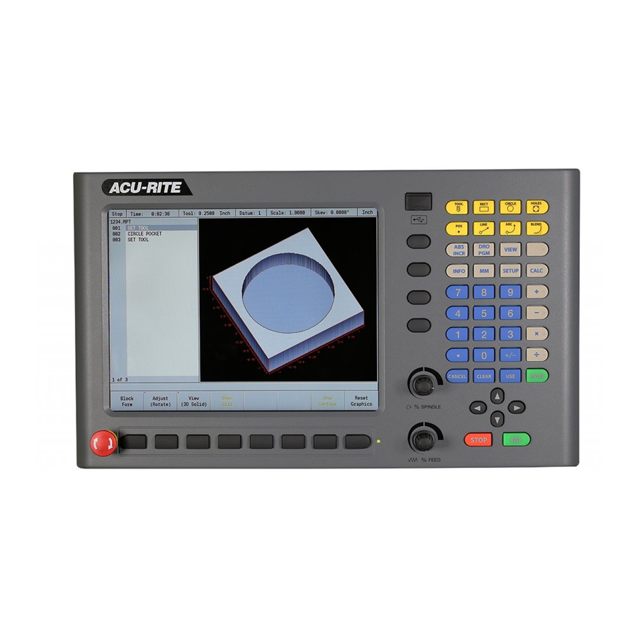
2.6 Overview of Components 2.6.1 MILLPWR Control MILLPWR Arm˜mount compact contouring control with integrated main computer, flat-panel LCD display and integrated operating keys. 3 analog closed-loop axes (1 VPP or EnDat). Up-to 4 encoder inputs. Analog nominal-value to servo drives. -
Page 18: Keys On Visual Display Unit
DRO display or Program mode. view key opens menu for setting part graphic display parameters, i.e. type, orientation. INFO key opens on-screen manual. MM key toggles between INCH or MM mode. SETUP key opens configuration menu. ACU-RITE Technical Manual MILLPWR... -
Page 19: Numerical Keys
Numerical keys Function Zero key. One key. Two key. Three key. Four key. Five key. Six key. Seven key. Eight key. Nine key. Decimal key. Plus / Minus key. Axis Keys Function Axis keys open the datum, or preset form. Soft Keys Function Soft keys execute the key directly... -
Page 20: Navigation Keys
2.6.4 Calculator Function keys Function blank key opens the user defined MILLing function data input form. CALC key opens the trig calculator. Plus key. Minus key. Multiplier key divide key. 2.6.5 Potentiometer for feed rate Feed rate ACU-RITE Technical Manual MILLPWR... -
Page 21: Milling Function Keys
2.6.6 Milling Function keys Function tool key opens the Tool data input menu. rect key opens the rectangle MILLing data input menu. circle key opens the circle MILLing data input menu. holes key opens the hole pattern data input menu. Pos key opens the positioning data input menu. -
Page 22: Touch Probe Systems
Id. Nr. 272 714-03 KT 3D (metric) TS 220 Grounding Edge Finder Touch-trigger edge finder with cable connection for workpiece setup and measurement during machining. Id. Nr. 272 714-04 KT 3D (Inch) Id. Nr. 272 714-03 KT 3D (metric) ACU-RITE Technical Manual MILLPWR... - Page 23 TS 640, TS 440 touch probe Touch-trigger probe with infrared transmission, for workpiece setup and measurement during machining. Id. Nr. 620 189-xx TS 640 Id. Nr. 620 046-xx TS 440 Id. Nr. 631 225-xx SE 640 transmitter- receiver unit Id. Nr. 626 001-xx SE 540 transmitter- receiver unit TS 640...
-
Page 24: Documentation
2.6.9 Documentation Items supplied with the control include: User’s Manual Id. Nr. MILLPWR User's Manual 1034384-20 ACU-RITE Technical Manual MILLPWR... -
Page 25: Brief Description
2.7 Brief Description Specifications MILLPWR MILLPWR Compact contouring control with integrated main computer, flat-panel display and MILLPWR operating panel. Intel Celeron processor with 1 GHz Working memory: 1GB DDR SDRAM Four position encoder inputs 1 V Axes ... - Page 26 Integral PLC PLC memory 256 MB on CFR memory card Program format Statement list PLC main memory (RAM) Dynamic, determined by the free main memory of the control PLC cycle time 12 ms (can be set) ACU-RITE Technical Manual MILLPWR...
- Page 27 Operation: 0 to +40 °C (+32 °F to +113°F) Storage: –35 °C to +65 °C (–31 °F to +149 °F) User functions MILLPWR Program entry ACU-RITE conversational ISO G-Code Fixed cycles Drilling/boring cycles for drilling, peck drilling, reaming, boring, counterboring, tapping with or without floating tap holder ...
- Page 28 Actual positions can be transferred directly into the part program Test graphics Graphical simulation before a program run, also while another program is being run Plan view, view in three planes, 3-D view Magnification of details ACU-RITE Technical Manual MILLPWR...
-
Page 29: Accessories
Accessories Accessories MILLPWR Touch probe systems TS 220 triggering 3-D touch probe with cable connection, or TS 440, TS 640 triggering 3-D touch probe with infrared transmission KT 3D Grounding Edge Finder. Data transfer software TNCremoNT PLC development software PLCdesignNT Software for configuration ConfigDesign... -
Page 30: Software
PLCdesignNT 2.5. The PLC setup archive is installed on the control in the same manner as a software update. 2.8.3 Enabling Software Options On the standard version of the MILLPWR , three control loops (3 axes) are enabled. ACU-RITE Technical Manual MILLPWR... -
Page 31: Enabling Software Options
Enabling software To enable options, proceed as follows: options While in the DRO mode, first press Setup key. Enter the code number 222 and confirm your entry by pressing OK. The following dialog box will appear: Display Meaning Control Type Control model (=MILLPWR General Key... -
Page 32: Updating Software
USB drive is present which contains a software update, the control will automatically start a software update. The required format for the software update on the USB drive is as follows: <DRIVE>:\install\setup.zip. ACU-RITE Technical Manual MILLPWR... -
Page 33: Procedure For Updating The Software
2.8.5 Procedure for updating the software Shut down the control software using the normal method of pressing the Shutdown soft key and then confirming the shutdown by pressing YES. Wait for the screen message which indicates that it is safe to switch off power, or restart. -
Page 34: Data Backup
, is the recommended method for data backup and re- storing. Refer to its bundled user guide for usage instructions. 2.9 Software Releases 2.9.1 NC Software 751 005-xx NC software 751 005-01 Release: 12/2011 ... Initial version ACU-RITE Technical Manual MILLPWR... -
Page 35: Pc Software Utilities
2.10 PC Software Utilities 2.10.1 Support Support for Remote Diagnostics PC software Remote Diagnostics offers numerous possibilities for remote maintenance and remote diagnosis of the MILLPWR . Along with transmission of the screen contents, all keys of the control can be operated remotely, for example. In addition, comprehensive diagnostic possibilities, such as outputting of control logs, are available. - Page 36 Contents of the message to the remote service host Format: String Input: Max. 500 characters The contents serve to identify the machine, e.g. machine model and serial number. Default: No value, parameter optional Access: LEVEL2 Creation: ACU-RITE Technical Manual MILLPWR...
- Page 37 MP_period Duration of repeated transmission of the message to the service host Format: Numeric value Input: 0 to 10 [s] Transmission the report is repeated during the specified period of time in seconds until the function is activated or the time entered in the MP_timeOut parameter is exceeded.
- Page 38 Subnet mask of the server network Format: String Input: Max. 500 characters Enter the subnet mask of the server as four decimal numbers separated by periods (IP address in dotted-decimal notation). Default: No value, parameter optional Access: LEVEL2 Creation: ACU-RITE Technical Manual MILLPWR...
-
Page 39: Management
2.10.2 Management: HEIDENHAIN Corporation offers many other useful PC software utilities free of charge. These include TNCremoNT for transferring files, PLCdesignNT for managing the PLC program and PLC key menu, and ConfigDesign for managing configuration settings. These utilities can be downloaded at http:// filebase.heidenhain.com. - Page 40 ACU-RITE Technical Manual MILLPWR...
-
Page 41: Mounting And Electrical Installation
3 Mounting and Electrical Installation 3.1 General Information Attention Keep the following in mind during mounting and electrical installation: National regulations for power installations Interference and noise immunity Conditions of operation Mounting attitude 3.1.1 Safety Precautions Danger Ensure that the main switch of the control or machine is switched off when you engage or disengage connecting elements or connection clamps. -
Page 42: Degrees Of Protection
For cables in metallic ducting, adequate decou- pling can be achieved by using a grounded separation shield. Shielding according to EN 50 178 Use potential compensating lines with 6 mm cross-sections Use only genuine HEIDENHAIN cables, connectors and couplings ACU-RITE Technical Manual MILLPWR... -
Page 43: Environmental Conditions
3.2 Environmental Conditions 3.2.1 Storage and operating temperatures Limit values Device Air approaching the Temperature range outside device in the console the console MILLPWR 32°F (0°C) to 122°F (50°C) 32°F (0°C) to 113°F (45°C) Compact- 32°F (0°C) to 158°F (70°C) 32°F (0°C) to 113°F (45°C) (no Flash card direct exposure to sunlight). -
Page 44: Humidity During Operation
3.2.4 Mechanical Vibration Permissible vibration: ± 0.075 mm, 10 to 41 Hz 5 m/s , 41 Hz to 500 Hz Permissible shock: 100 m/s , 11 ms during operation 300 m/s , 11 ms during transport ACU-RITE Technical Manual MILLPWR... -
Page 45: Console Back Panel
3.3 Console Back Panel Item Description Power switch Power connector Servo Power connector Earth (ground) terminal Ethernet port USB port KT 130 Edge Finder Pendant (Remote switch) RS-232-C connector Auxiliary Machine Interface (AMI); for future expansion. Servo connector (X, Y, and Z) Grounding Edger Finder Encoder Inputs (W and Z axis) 3.3 Console Back Panel... -
Page 46: Power Supply
(max. 320 W) Note If USB components that are connected to the console require more than 0.5 A, a separate power supply becomes necessary for these components. One possibility is the USB hub from HEIDENHAIN (582 884-02). ACU-RITE Technical Manual MILLPWR... -
Page 47: Buffer Battery
3.5 Buffer Battery Note Make a data backup before changing the buffer battery. Danger When exchanging the buffer battery, remember: Switch off the machine and the MILLPWR The buffer battery may be exchanged only by trained personnel. Battery type: 1 lithium battery, type CR 2450N (Renata), Id. Nr. 315 878-01 If the voltage of the buffer battery falls below 2.6 V, the error message Exchange buffer battery appears. -
Page 48: Encoder Connections
TS 440, TS 640, touch-trigger probes with infrared transmission for work- piece setup and measurement during machining KT 3D, a grounding edge finder with cable connection for workpiece setup and measurement during machining. For suitable connecting cables, see “Cable Overview” at end of chapter. ACU-RITE Technical Manual MILLPWR... -
Page 49: Triggering Touch Probe For Workpiece Measurement
3.7.1 Triggering Touch Probe for Workpiece Measurement Touch probe con- nection Note The interface complies with the requirements of EN 50 178 for “low voltage electrical separation.” Pin layout for TS 220: MILLPWR Adapter cable 274 543-xx TS 220 Female Assignment Male Color... - Page 50 100 mA Battery warning 0 V (U Trigger signal Trigger signal 11 to 15 Do not assign External External Hsg. External shield Hsg. shield Hsg. Hsg. shield Hsg. a. Stylus at rest means logic level HIGH. ACU-RITE Technical Manual MILLPWR...
-
Page 51: Data Interfaces
3.8 Data Interfaces Please note: Maximum cable length with Ethernet 400 m (shielded), 100 m (unshielded) Maximum cable length with RS-232-C/V.24 is 20 meters. General Keep the following information in mind when connecting external peripheral information devices to the data interfaces of the control: ... -
Page 52: Ethernet Interface Rj45 Connection
Note The interface complies with the requirements of EN 50 178 for “low voltage electrical separation.” Meanings of the LEDs on the Ethernet data interface: Status Meaning Blinks Interface active Interface inactive 100-Mb network 10-Mb network ACU-RITE Technical Manual MILLPWR... -
Page 53: Rs-232-C/V.24
3.8.2 RS-232-C/V.24 Data Interface Pin layout: Note The interface complies with the requirements of EN 50 178 for “low voltage electrical separation.” Adapter block 25-pin: MILLPWR Conn. cable 365 725-xx Adapter block Conn. cable 274 545-xx 310 085-01 Male Assignment Female Color Female... -
Page 54: Usb Interface
Connections on the USB hub (582 884-02): Connection designation Function 24 V power supply X140 USB input (to the MILLPWR X141 USB output 1 X142 USB output 2 X143 USB output 3 X144 USB output 4 ACU-RITE Technical Manual MILLPWR... -
Page 55: Cable Specifications
3.9 Cable Specifications Device Id. Nr. Max. bending radius Max. bending radius Cable (rigid configuration) (frequent flexing) diameter ≥ 40 mm ≥ 100 mm TS 220 274 543-xx ø 8 mm ≥ 40 mm, ≥ 100 mm, SE 640, SE 540 310 197-xx, ø... -
Page 56: Dimensions
3.10 Dimensions 3.10.1 MILLPWR Weight: 8.0 kg Dim: Inch ACU-RITE Technical Manual MILLPWR... -
Page 57: Adapter Block For The Data Interface
3.10.2 Adapter Block for the Data Interface RS-232-C/V.24 adapter block and RS-422/V.11 adapter block 3.10 Dimensions... -
Page 58: Usb Hub
3.10.3 USB Hub ACU-RITE Technical Manual MILLPWR... -
Page 59: Touch Probe Systems
3.10.4 Touch Probe Systems Adapter cable for TS Mounting coupling for quick connection Mounting coupling for HEIDENHAIN standard connector 3.10 Dimensions... -
Page 60: Adapter Cable For Ts 120/Ts 220
TS 220 Adapter cable for TS 120/TS 220 ACU-RITE Technical Manual MILLPWR... -
Page 61: Se 640 Transmitter-Receiver Unit
SE 640 transmitter- receiver unit 3.10 Dimensions... -
Page 62: Se 540 Transmitter-Receiver Unit
SE 540 transmitter- receiver unit ACU-RITE Technical Manual MILLPWR... - Page 63 TS 440 TS 640 3.10 Dimensions...
- Page 64 ACU-RITE Technical Manual MILLPWR...
-
Page 65: Machine Parameters
4 Machine Parameters 4.1 General Information A control must have access to specific machine data (e.g., traverse distances, acceleration, speeds) before it can execute its programmed instructions. You define these data in machine parameters. Each machine has its own set of parameters. - Page 66 A unique key name is assigned to each channel. All objects that apply to a certain channel must be identified with this key. Example: The key name “Channel1” for all objects that belong to Channel1. Note Key names should be short and clear, and refer to the function. ACU-RITE Technical Manual MILLPWR...
-
Page 67: Managing Parameters
4.2 Managing Parameters 4.2.1 Entering and Editing Machine Parameters Press the Setup key, the CONFIG DATA key, enter the password "222", and again press the CONFIG DATA key. The object tree for the machine parameters is displayed. The actual machine parameters with their values are located on the lowest level of this tree. -
Page 68: Icons In The Object Tree
Can be read but not edited Cannot be read or edited Parameter type identifiable by folder icon The parameter type can be identified by the folder symbol in the machine- parameter tree structure: Entity (object) Array (list) Key (keyname) ACU-RITE Technical Manual MILLPWR... - Page 69 Table view in the configuration editor In the configuration editor you can switch from the familiar tree view to a table view. This is especially useful when configuring the parameter blocks, since now the parameters of all axes are visible at a glance: 4.2 Managing Parameters...
-
Page 70: Displaying Help Texts
Additional information, such as the unit of measure, the initial value, or a selec- tion list, is also displayed. If the selected machine parameter matches a para- meter in the MILLPWR , the corresponding MP number is shown. To exit the help text, press the Ok key. ACU-RITE Technical Manual MILLPWR... -
Page 71: Entering And Editing Parameters
Entering and In order to change the input values, open an input or selection dialog box for editing parameters the selected parameter with the RIGHT ARROW key, ENTER key. In selection dialogs, press the UP/DOWN ARROW key and then the ENTER key to select the desired value from the list. -
Page 72: Changing Key Names
MP change list in the configuration editor A machine-parameter change list is displayed after pressing the SAVE keys. The Configuration data changed window gives you an overview of all changed parameters. You can save, discard or cancel the changes: ACU-RITE Technical Manual MILLPWR... -
Page 73: Find Function
Find function Search for objects and parameters within the configuration editor using a dia- log box. Open the dialog box with the FIND key. The current word or a part of the object or parameter name may be entered as the search term. - Page 74 The pre- fixed key names then serve to distinguish between the numbers. Structure of an MP number: ACU-RITE Technical Manual MILLPWR...
-
Page 75: Finish Editing
Finish editing Press the Exit key to return to the main menu. The control asks if the changed data are to be saved or discarded (see Saving input values). 4.2.2 Managing Configuration Files The configuration data is saved in several files with the extension .cfg. This enables you to establish the correct configuration for different types of machines by selecting the appropriate files from the paths entered. -
Page 76: Attribute Information
95148. Enter the code number in the Programming mode using the MOD key. The end user must not be told of the code number 95148. LEVEL4 access right Machine parameters on LEVEL4 can only be accessed by HEIDENHAIN. The machine manufacturer can only read them. ACU-RITE Technical Manual MILLPWR... -
Page 77: Reaction To Change
Reaction to change The following reactions can occur when machine parameters are changed: NOTHING RESET Information on which reactions occur for which machine parameters is given later in this chapter. See "Overview of the Machine Parameters" on page 93.. Reaction NOTHING Data with this reaction can be changed at any time, including during program run. -
Page 78: Remove Syntax Error
(configuration data). If, after a software update, configuration errors occur while the control is star- ting up, the previous executable version can be reactivated. Then find and correct the error by using the update rules. ACU-RITE Technical Manual MILLPWR... -
Page 79: Backup Of Parameters
4.2.8 Backup of Parameters The DATA BACKUP key enables you to save and restore configuration data as well as to create text files with the current machine parameters: The following functions are available: Save parameter files in backup The following file name is suggested: %OEM%\service\BKUPyear-month-day_.ZIP Append meaningful information to this name, for example, the control model, software version, etc. - Page 80 TNCbackup is part of the TNCremoNT and is available free of charge from HEIDENHAIN, for example from the file base on the internet (filebase.heidenhain.de). Note A backup should be performed after commissioning and every time the machine parameters have been edited. ACU-RITE Technical Manual MILLPWR...
-
Page 81: Allocation Of Configuration Data
4.3 Allocation of Configuration Data The configuration data is saved in several files with the extension .cfg. See "Managing Configuration Files" on page 75. Paths saved in the file config- files.cfg refer to these files. This allocation has already been specified by HEIDENHAIN when the software is delivered, but it can be adapted by the OEM to his requirements. -
Page 82: 3-Axis System
"%OEM%\\config\\oem.cfg", "%OEM%\\config\\axlist.cfg", "%OEM%\\config\\kin_1.cfg", "%OEM%\\config\\kin_2.cfg", "%OEM%\\config\\kin_mp.cfg", "%OEM%\\config\\axis_x.cfg", "%OEM%\\config\\axis_y.cfg", "%OEM%\\config\\axis_z.cfg", "%OEM%\\config\\axis_w.cfg", "%OEM%\\config\\axis_s.cfg", "%OEM%\\config\\plc.cfg", "%OEM%\\config\\plc_oem.cfg "%OEM%\\config\\oemtable.cfg", "%USR%\\config\\user.cfg" Please note that multiple kinematics configurations are indicated. This enables you to use all variants. ACU-RITE Technical Manual MILLPWR... -
Page 83: Structure Of A Parameter File
4.4 Structure of a Parameter File The individual machine parameters are collected into parameter objects in the *.cfg parameter files. A parameter object has a name, of which the first three letters are always “Cfg.” The name is followed by an open parenthesis and a “key”... - Page 84 -- Comment to the end of the line The text in the line after “--” (double hyphen) is ignored. Characters for comment beginning. Comment distributed over several Everything between the comment lines beginning and end is ignored. Characters for comment end. ACU-RITE Technical Manual MILLPWR...
-
Page 85: Machine Parameter Subfiles
4.5 Machine Parameter Subfiles Individual data from the configuration files can be taken into the MP subfiles. These subfiles can be superimposed on the machine parameters during run time. In principle, all files that do not require a system restart can be superimposed. The MP subfiles are usually activated by the PLC, but they can also be acti- vated manually by using the configuration editor. - Page 86 %SYS%\\config\\jh.cfg file as follows: CfgNoNotification ( key:="plc.QM4174", objectNames:=[ "CfgOsci", "CfgOsciFile", "CfgOsciColor", "CfgOsciSetUp", "CfgOsciChannel", "CfgOsciTrigger", "CfgOsciDisplay", "CfgSelectFile", "CfgRecentFileList", "CfgDisplayData", "CfgPosDisplayPace", "CfgJogIncrement", "CfgInterpretOption", "CfgHandWheelFactor", "CfgAutoStartData", "CfgFeedRate", "CfgLayoutData", "CfgTablePath", "CfgEditor", "CfgGeoRotWorkPlane", "CfgUserPath", "CfgUnitOfMeasure", "CfgProgramMode", "CfgPassword", "CfgFunctionProtection", "CfgActualProtection", "CfgJhProtection", "CfgModSkText"] ACU-RITE Technical Manual MILLPWR...
-
Page 87: Activation By The Plc
Activation by the Subfiles are activated by Module 9034. In this case the symbolic PLC operand NN_GenCycleAfterReConfig (M4174) will not be set. Module 9034 Load a machine parameter subfile With this module you load the contents of the given configuration file into the main memory. -
Page 88: Displaying/Editing Data Records In The Configuration
4.5.3 Displaying/Editing Data Records in the Configuration Editor Use the SELECT RECORD key to choose between the following views: The following overview shows which values of an object (object1, 2, 3) are dis- played in the individual views: ACU-RITE Technical Manual MILLPWR... -
Page 89: Basic Data
Basic data This view shows the data imported during system start-up. Any changes will be rewritten to the respective basic files. Loaded subfile(s) You must have loaded a subfile during system start-up (with "CfgPortionFiles") or by key for the subfile to be shown. If you select a subfile, only the data of the subfile are displayed in the configuration editor. -
Page 90: Read Or Change Machine Parameters Via A Plc Module
<index> Index within an array; 0= for parameters without array <factor> Conversion factor for real to integer, and vice-versa <value> Value of the parameter, e.g.: 123456 <string> String number (0 to 15) <error> See module description ACU-RITE Technical Manual MILLPWR... - Page 91 Module 9431 Read the numeric value of a machine parameter Use this module to read the value of the given machine parameter from the run-time memory. Call only in a submit job. Call: B/W/D/K/S<object name> B/W/D/K/S<key name> B/W/D/K/S<MP name> B/W/D/K <index> B/W/D/K <factor>...
- Page 92 0: Module executed correctly 1: Parameter does not exist, cannot be changed, or cannot be changed during program run 3: Fatal error (no connection to config server, etc.) 6: Not called in submit/spawn 7: Parameter is not a string ACU-RITE Technical Manual MILLPWR...
-
Page 93: Overview Of The Machine Parameters
4.7 Overview of the Machine Parameters 4.7.1 "System" group Globally effective machine parameters, valid for the complete system. Parameter Function and input Behavior MP number Access SW version CfgAxes Definition of existing axes of all channels in the system; Create entries for all axes of the machine. Also for spindles and PLC axes. axisList Key names for all axes on the machine RESET... - Page 94 Input I32 has no effect on the monitoring functions. Default: maxTouchFeed Absolute maximum probing feed rate 100104 Limitation of values from touch probe table. LEVEL3 Format: Numerical value Input: 0.000 to 99,960.000 [mm/min] Default: 960.000 [mm/min] ACU-RITE Technical Manual MILLPWR...
- Page 95 Parameter Function and input Behavior MP number Access SW version CfgMachineSimul MILLPWR can be switched to programming station mode; No drives are enabled. NC programs cannot be run but only created and tested. Machine functions are simulated. simMode Sets the type of programming station mode RESET 100201 Format:...
- Page 96 3 to 10 [· MP_ipoCycle] Default: 7 (= 21 ms) watchdogTime Delayed switch-off of SH1 RESET 100303 Program the monoflop time for watchdog 2 here. LEVEL3 MP2172 Format: Numerical value Input: 1 to 30 [s] Default: 3 [s] ACU-RITE Technical Manual MILLPWR...
- Page 97 Parameter Function and input Behavior MP number Access SW version CfgFilter Default configuration of the nominal position value filters, applies to all axes. Can be axis-specifically overwritten. defaultPosition: Default configuration of the nominal position value filter for all linear axes. ...
- Page 98 NC axes and spindles are shown only if they belong to the active kinematic configuration of a machining channel. Auxiliary axes are always displayed. show always: NC axes, spindles and auxiliary axes are always dis- played. Default: show NC axis/spindle only if in kinematics ACU-RITE Technical Manual MILLPWR...
- Page 99 Parameter Function and input Behavior MP number Access SW version positionWinDisplay Type of position display in the position window NOTHING 100803 Specifies the default setting for the position display in LEVEL1 the position window. The machine operator can change the setting with the MOD key. Format: Selection menu Input:...
- Page 100 0.05 [mm] or [°] 0.01 [mm] or [°] 0.005 [mm] or [°] 0.001 [mm] or [°] 0.0005 [mm] or [°] 0.0001 [mm] or [°] 0.00005 [mm] or [°] 0.00001 [mm] or [°] Default: 0.001[mm] or [°] ACU-RITE Technical Manual MILLPWR...
- Page 101 Parameter Function and input Behavior MP number Access SW version displayPaceInch Display step for position display in inches NOTHING 101002 Format: Selection menu LEVEL1 MP7290.0-8 Input: 0.005 inches 0.001 inches 0.0005 inches 0.0001 inches 0.00005 inches 0.00001 inches Default: 0.001[inches] 4.7 Overview of the Machine Parameters...
- Page 102 SW version CfgUnitOfMeasure Definition of unit of measure in effect for display unitOfMeasure Unit of measure for display and user interface 101101 Format: Selection menu LEVEL1 Input: metric: Metric measurement system inch: Inch measurement system Default: metric ACU-RITE Technical Manual MILLPWR...
- Page 103 Parameter Function and input Behavior MP number Access SW version CfgDisplayLanguage Settings of the NC and PLC conversational language ncLanguage NC conversational language 101301 Format: Selection menu LEVEL1 MP7230.0 Input: ENGLISH – English FRENCH – French SPANISH – Spanish Default: ENGLISH plcDialogLanguage PLC conversational language...
- Page 104 MP_background Default: black select Color for selected channel NOTHING 101409 Format: Selection menu LEVEL3 MP7365.3 Input: see MP_background Default: grid Color for grid NOTHING 101410 Format: Selection menu LEVEL3 MP7365.1 Input: see MP_background Default: medium_gray ACU-RITE Technical Manual MILLPWR...
- Page 105 Parameter Function and input Behavior MP number Access SW version cursorText Color for the cursor and text NOTHING 101411 Format: Selection menu LEVEL3 MP7365.2 Input: see MP_background Default: really_dark_gray 4.7 Overview of the Machine Parameters...
- Page 106 Shut down control Default: RESTART shutdownOnError Behavior when RESET errors are acknowledged NOTHING 101602 Definition of behavior of the TNC 320 when a RESET LEVEL1 error is acknowledged. MP4040 Format: Selection menu Input: see MP_shutdownOnConfig Default: RESTART ACU-RITE Technical Manual MILLPWR...
- Page 107 Parameter Function and input Behavior MP number Access SW version shutdownOnUser Behavior during switch-off of the TNC 320 by soft NOTHING 101603 LEVEL1 Determines the behavior of the TNC 320 when the MP4040 control is shut down by soft key. Format: Selection menu Input:...
- Page 108 Delay time until PLC output is set NOTHING 101607 Time after shut down of the control until setting the LEVEL1 PLC output from MP_powerOffPort. MP4042 Format: Numerical value (optional parameter) Input: 0 to 1000 [s] Default: 0 [s] ACU-RITE Technical Manual MILLPWR...
- Page 109 Parameter Function and input Behavior MP number Access SW version CfgTable Display properties of the table editor tableView Selection of various table views NOTHING The table view can be selected in the table editor via LEVEL2 the screen layout (applies to the first six entries). The last two entries are used in the Edit table characte- ristics or Select from table mode.
- Page 110 The respective paths may contain NC programs or tables, for example, floppy disk drive directories, HDR or CFR directories, network drives, etc. Format: List [0...10] Input: String of max. 260 characters ACU-RITE Technical Manual MILLPWR...
- Page 111 Parameter Function and input Behavior MP number Access SW version CfgUserPath Paths for the end user; Directories that are to be visible in the file manager. These entries can be edited by the machine operator. ncDir List of drives and/or directories NOTHING 102201 The drives and directories entered here are visible in...
- Page 112 Name of text file for PLC dialogs NOTHING 102305 The path %OEM%\plc\language\en is fixed, whereby LEVEL2 the last subdirectory is formed from the configured language (here en = English). Format: String Input: File name of max. 260 characters ACU-RITE Technical Manual MILLPWR...
- Page 113 Parameter Function and input Behavior MP number Access SW version softkeyProject Path/name of project file for PLC soft keys (*.XRS) NOTHING 102306 Format: String LEVEL2 Input: Path and name of max. 260 characters compCfgFile Path/name of configuration file for the PLC compi- NOTHING ler (*.MCG) 102308...
- Page 114 Behavior MP number Access SW version simModelPath Path for saving model data NOTHING 102401 The TNC 320 saves model data of simulated NC pro- LEVEL3 gram via this path. Format: String Input: Path, max. 500 characters ACU-RITE Technical Manual MILLPWR...
- Page 115 Parameter Function and input Behavior MP number Access SW version CfgTablePath Path for tables that can be activated in SQL instructions through the symbolic name (SQL synonym) given as the key name. When accessing the table via SQL commands, only enter the synonym instead of the complete path and file name, for example, TOOL instead of TNC:\table\tool.t.
- Page 116 Maximum available memory for cache files NOTHING 102803 If the available memory reserve falls below the defi- LEVEL3 ned value [MB], 10% of the cache is automatically deleted. Format: Numerical value Input: 0 to 30 [MB] Default: 30 [MB] ACU-RITE Technical Manual MILLPWR...
- Page 117 Parameter Function and input Behavior MP number Access SW version ProgramManager Configuration of the program manager for file management. CfgFileType Assignment of the editor to a file type; Depending on the file extension, a standard editor as well as further data required for controlling the editing process are assigned.
- Page 118 Lock the SELECT TYPE soft key for selection of the file type LOCK_FILETYPE: Lock file types from editing LOCK_ALL: Lock the SELECT TYPE soft key for selection of the file type and lock the file type to prevent editing ACU-RITE Technical Manual MILLPWR...
- Page 119 Parameter Function and input Behavior MP number Access SW version CfgPathProtection Access rights to drives and directories [Key name with drive or directory specification (path name)] e.g. %OEM%\ or %USR%\CONFIG etc. protection Access rights to the drive or directory NOTHING 103101 Format: Selection menu...
- Page 120 The error that occurred is entered in the PLC error log. DISPLAY: The error that occurred is shown on the control screen. STOP_PLC: The current PLC program is stopped if an error occurs during a PLC module call. Default: ACU-RITE Technical Manual MILLPWR...
- Page 121 Parameter Function and input Behavior MP number Access SW version CfgPlcOemError Configuration of PLC error messages in the PLC error table; Markers can be set, depending on the column MTYPE in the PET table. notifyInfo Symbolic name or the number of a marker NOTHING 103301 This marker is set if there is a message pending from...
- Page 122 103407 LEVEL3 Format: Numerical value (optional parameter) Input: 0.0001 to 0.1 Default: 0.0005 overrideIntegDelta Compensation for thermal noise in override poten- NOTHING tiometers 103408 LEVEL3 Format: Numerical value (optional parameter) Input: 0.0001 to 1.0 Default: 0.025 ACU-RITE Technical Manual MILLPWR...
- Page 123 Parameter Function and input Behavior MP number Access SW version CfgPlcTimer Default values for PLC timers and counters A change only becomes effective after a PLC program restart. [Key name of the PLC timer or counter] Process marker for the timer or counter 103503 Identifies the timer or counter for which the respec- LEVEL3...
- Page 124 Number of the physical output port on the PL NOTHING 103601 Format: Numerical value LEVEL2 (optional parameter) Input: 0 to 31 597 110-02 time Delay time during switch-off NOTHING 103602 Format: Numerical value LEVEL2 (optional parameter) Input: 0.1 to 5.0 [s] 597 110-02 ACU-RITE Technical Manual MILLPWR...
- Page 125 Parameter Function and input Behavior MP number Access SW version CfgPlcFastInput Configuration of fast PLC inputs; Definition of numbers, operands and edge detection. Please remember that the time between two edges must be longer than the time from 'MP_CfgCycleTimes/ipoCycle'. number Numbers of fast PLC inputs 103701 Format:...
- Page 126 Symbolic name or number of the PLC marker that RESET is set for acknowledging the strobe. 103904 LEVEL3 no entry: (optional parameter) The strobe is reset with the PLC marker entered in MP_signal. Format: String Input: PLC operand, max. 80 characters ACU-RITE Technical Manual MILLPWR...
- Page 127 Parameter Function and input Behavior MP number Access SW version code Symbolic name or number of the PLC word marker for RESET the M code 103905 LEVEL3 Name of the PLC word marker in which the M code is (optional parameter) transferred to the PLC.
- Page 128 M function output at block end or block beginning. RESET 103910 Format: Selection menu LEVEL3 Input: TRUE or FALSE TRUE: Function is executed at block end. FALSE: Function is executed at beginning of block. Default: FALSE ACU-RITE Technical Manual MILLPWR...
- Page 129 Parameter Function and input Behavior MP number Access SW version blockSearch Code output also during during the block scan RESET 103911 Format: Selection menu LEVEL3 Input: TRUE or FALSE TRUE: Function is also output during the block scan. FALSE: Function is not output during the block scan.
- Page 130 The data connected with the output of the strobe is saved without synchronization with the PLC program and the output is immediately acknowledged. Format: String Input: PLC operand, max. 80 characters ACU-RITE Technical Manual MILLPWR...
- Page 131 Parameter Function and input Behavior MP number Access SW version acknowledge Symbolic name or number of the PLC marker that RESET is set for acknowledging the strobe. 104003 LEVEL3 no entry: (optional parameter) The strobe is reset with the PLC marker entered in MP_signal.
- Page 132 The parameter is effective for implementing the state of the function in the status display and during block scan. Format: List [0...10] Input: 0 to 9 999 ACU-RITE Technical Manual MILLPWR...
- Page 133 Parameter Function and input Behavior MP number Access SW version blockSearch Code output also during during the block scan RESET 104014 Format: Selection menu LEVEL3 Input: TRUE or FALSE TRUE: Function is also output during the block scan. FALSE: Function is not output during the block scan.
- Page 134 [Key name of the T strobe] e. g. ToolCall, ToolDef etc. type Type of T function RESET 104101 Format: Selection menu LEVEL3 Input: Remove tool from spindle Insert tool in spindle Prepare the next tool change ACU-RITE Technical Manual MILLPWR...
- Page 135 Parameter Function and input Behavior MP number Access SW version condition Condition for sending the strobe to the PLC RESET 104102 Format: Selection menu LEVEL3 (optional parameter) Input: COND_ALWAYS: Strobe is output with every programmed S code COND_ST: Strobe is output only if spindle speed changes ...
- Page 136 104112 LEVEL3 The definition of this marker is not necessary if no spe- (optional parameter) 597 110-03 cial tools are used. Format: String Input: PLC operand, max. 80 characters ACU-RITE Technical Manual MILLPWR...
- Page 137 Parameter Function and input Behavior MP number Access SW version revoke Numbers of functions whose effect will be can- RESET celed by the output of the strobe. 104113 LEVEL3 In the list, enter the numbers of the functions whose (optional parameter) effect will be canceled when this code is output.
- Page 138 MP_data. FALSE: No offset is used. The TNC 320 always issues the M function given under MP_min. Both transferred numerical values are written to the array of double words entered in MP_data. ACU-RITE Technical Manual MILLPWR...
- Page 139 Parameter Function and input Behavior MP number Access SW version CfgToolChange Definition of the tool change sequences; With tool change sequences, references to sequences of strobe messages for a tool call are designa- ted. The output and sequence of T strobes can be defined via scripts with the TNC 320. sequT0Text Loading an external tool RESET...
- Page 140 At least one tool has a fixed pocket in 118415 LEVEL3 the tool magazine, and at least one tool requires (optional parameter) special handling Format: Selection menu with scripts from CfgOemScript Input: Key name of a WZW sequence ACU-RITE Technical Manual MILLPWR...
- Page 141 Parameter Function and input Behavior MP number Access SW version sequText (typical for lathes with turrets) RESET Tool-change sequence for calling an external tool 118416 LEVEL3 without loading it in the spindle (optional parameter) Format: Selection menu with scripts from CfgOemScript Input: Key name of a WZW sequence...
- Page 142 118511 LEVEL3 (optional parameter) sequTintTintS (see CfgToolChange) RESET 118512 LEVEL3 (optional parameter) sequTintTintF (see CfgToolChange) RESET 118513 LEVEL3 (optional parameter) squTintTintSF (see CfgToolChange) RESET 118514 LEVEL3 (optional parameter) sequTint (see CfgToolChange) RESET 118515 LEVEL3 (optional parameter) ACU-RITE Technical Manual MILLPWR...
- Page 143 Parameter Function and input Behavior MP number Access SW version CfgSimPosition Definition of simulated tool change position during mid-program startup; Specifies the simulated tool-change position for TOOL CALL during mid-program startup. [Key name of the T strobe] value: List with machine axes. The index corresponds to the logical axis number in MP_axisList. axis Key name of the axis 113501...
- Page 144 Define a curve with up to 64 interpolation points. The override values are taken from the curve. Linear interpolation is again effective above the last inter- polation point specified. Format: Array [0...63] Input: 0 to 200 ACU-RITE Technical Manual MILLPWR...
- Page 145 Parameter Function and input Behavior MP number Access SW version CfgPlcOverrideS Configuration of the spindle override [Key name of the spindle] e.g. S, spindle etc. minimal Minimum value for override RESET 104401 Format: Numerical value LEVEL3 Input: 0 to 100 [%] Default: maximal Maximum value for override...
- Page 146 The key names of these objects are arbitrary and are defined by the OEM. If the data is to be copied into the PLC run-time image, the key names must correspond to the names of the PLC double words, for example NP_DG_WZW_Pos_Spindle (with API 3.0) etc. ACU-RITE Technical Manual MILLPWR...
- Page 147 Parameter Function and input Behavior MP number Access SW version value List with user fixed decimal values PLC/Pgm (Position) run is locked 104701 Format: List [1...100] LEVEL3 (optional parameter) Input: -30 000 to +30 000 Max. of 4 decimal places ignorePlc Do not copy data object into the PLC image PLC/Pgm...
- Page 148 201802 in the block scan, this M function is output after the LEVEL3 tracked strobes. At a value of –1 there is no output. Format: Numeric value Input: -1 to 999 Default: -1, meaning no output ACU-RITE Technical Manual MILLPWR...
- Page 149 Parameter Function and input Behavior MP number Access SW version TableSettings Description of table types; Specifies the properties of the tables. CfgTableProperties Assignment of columns to a table type; Defines: The columns in the table The primary and foreign key With this information you can import a table or create a new one.
- Page 150 Definition of width for the column made in the table file. At least one character for the column name and LEVEL3 one character for spacing from the next column. Format: Numeric value Input: 2 to 50 (Column width, max. 50 characters) Default: ACU-RITE Technical Manual MILLPWR...
- Page 151 Parameter Function and input Behavior MP number Access SW version unit Data type of values in the column PLC/Pgm run is locked 105602 Format: Selection menu LEVEL3 Input: TEXT: Text entry SIGN: Algebraic sign + or – BIN: Binary number ...
- Page 152 If the attri- LEVEL3 (optional parameter) bute is not set or set to FALSE, values may be over- written. Format: Selection menu Input: TRUE: Values are write-protected FALSE: Values may be overwritten Default: FALSE ACU-RITE Technical Manual MILLPWR...
- Page 153 Parameter Function and input Behavior MP number Access SW version unitIsInch Column entry in inches PLC/Pgm run is locked 105609 If lengths and feed rates are to be specified in the column in a definite unit of measure, enter TRUE here LEVEL3 (optional parameter) for values in inches and FALSE for values in mm.
- Page 154 Number of a soft key variant PLC/Pgm run is locked 105703 Additional specification for a graphics soft key: Variant number of the soft key icon in the BMX file. LEVEL3 (optional parameter) Format: Numeric value Input: 0 to 2147483647 ACU-RITE Technical Manual MILLPWR...
- Page 155 Parameter Function and input Behavior MP number Access SW version choice Define a selection list for input values PLC/Pgm run is locked 105704 A selection element consists of a value/text pair. The text is displayed. LEVEL3 (optional parameter) When selected, the value belonging to the text is entered in the table.
- Page 156 Thus, this has not to be done during run time. Format: Numeric value Input: Group number 0 = Binding to Q parameter ACU-RITE Technical Manual MILLPWR...
- Page 157 Parameter Function and input Behavior MP number Access SW version number System data no. (NR) or Q parameter no. RUN/ LEVEL3 105903 Format: Numeric value (optional parameter) Input: System data no. or Q paramter no. if MP_id = 0 index System data index (IDX) RUN/ LEVEL3...
- Page 158 80 mm are shown. TYP == 21 Limits the displayed data record of the table so that only touch probes are shown. Format: String Input: Max. 80 characters CfgTablePrototype Path and file name for the prototypes of a table ACU-RITE Technical Manual MILLPWR...
- Page 159 Parameter Function and input Behavior MP number Access SW version [Key name (file extension) of the table prototype] e. g. TCH, D, PR etc. path Path/name for the prototypes of a table type PLC/Pgm run is locked 106101 Format: String LEVEL3 Input: Max.
- Page 160 Column name or column list which the values are copied to when returning from the selection in the LEVEL3 table, e.g. T,TNAME replaces the values in the columns T + TNAME. Format: String Input: Max. 50 characters ACU-RITE Technical Manual MILLPWR...
- Page 161 Parameter Function and input Behavior MP number Access SW version CfgTableUpdateList Tables to be checked for correct table format; Define tables here that should be automatically checked for correct table format when the control starts up. If the format is incorrect, the table is automatically corrected. Rules for the update are also taken into account.
- Page 162 Symbolic name of the machine parameter is dis- played. Default: FALSE hideWriteProtected Hiding write-protected parameters PLC/Pgm run is locked 106504 Format: Selection menu LEVEL3 Input: TRUE: Hide write-protected configuration objects FALSE: Display all write-protected configuration objects Default: TRUE ACU-RITE Technical Manual MILLPWR...
- Page 163 Parameter Function and input Behavior MP number Access SW version Network Configuration of interface connections Serial Configuration of serial interfaces CfgSerialPorts Data record belonging to the serial port; The data record for configuring the serial port is stored in CfgSerialInterface. activeRs232 Enable the RS-232 interface in the program mana- PLC/Pgm...
- Page 164 Under each key name, the properties of a serial port are defined. The data block to be active is speci- fied under CfgSerialPorts. baudRate Data transfer rate in baud PLC/Pgm run is locked 106701 Format: Selection menu LEVEL2 MP5040 Input: BAUD_110 BAUD_150 BAUD_300 BAUD_600 BAUD_1200 BAUD_2400 BAUD_4800 BAUD_9600 BAUD_19200 BAUD_38400 BAUD_57600 BAUD_115200 Default: BAUD_9600 ACU-RITE Technical Manual MILLPWR...
- Page 165 Parameter Function and input Behavior MP number Access SW version protocol Communications protocol PLC/Pgm run is locked 106702 Format: Selection menu LEVEL2 MP5030 Input: STANDARD: Standard data transfer. Data transferred line-by-line. BLOCKWISE: Package-based data transfer, so-called ACK/NAK protocol. Blockwise data transfer is controlled by the control characters ACK (Acknowledge) and NAK (Not Acknowledge).
- Page 166 106708 Format: Selection menu LEVEL2 MP5020 bit 1 Input: (optional parameter) TRUE: Ensures that the check sum does not correspond to a control character FALSE: Function not active Default: FALSE ACU-RITE Technical Manual MILLPWR...
- Page 167 Parameter Function and input Behavior MP number Access SW version rtsLow Idle state of the RTS line PLC/Pgm run is locked 106709 Format: Selection menu LEVEL2 MP5020 bit 8 Input: 597 110-03 TRUE: The idle state of the RTS line is logical LOW ...
- Page 168 (IP address in dotted- LEVEL2 (optional parameter) decimal notation). 597 110-03 Format: String Input: max. 500 characters Key code Define code numbers CfgChangePassword Changes existing HEIDENHAIN code numbers to the OEM's own code numbers. ACU-RITE Technical Manual MILLPWR...
- Page 169 Parameter Function and input Behavior MP number Access SW version [Key name = existing HEIDENHAIN code numbers] Specify existing HEIDENHAIN code numbers to be replaced by those of the OEM, e.g. 807667, 95148 etc. replaceWith New OEM password or code number PLC/Pgm run is locked 120501...
- Page 170 Name of the functions that are called by entering the password. Enter these names as key names in CfgModOemSoftkey and CfgCfgEditActivate. The password is defined by the key name under CfgOemPassword. Format: List [0...200] Input: Max. 18 characters ACU-RITE Technical Manual MILLPWR...
- Page 171 Parameter Function and input Behavior MP number Access SW version CfgCfgEditActivate Specifies the view of the configuration editor that is opened by entering the OEM password; The OEM may configure the tree structure and parameter display according to his requirements. [Key name of the configuration editor view] Use the function name entered in CfgOemPassword/funcList or CfgModOemSoftkey/funcKey as key name.
- Page 172 Control model PLC/Pgm run is locked 107501 Format: String LEVEL4 Input: Max. 16 characters, e.g. "TNC 320" ncVersion NC software version PLC/Pgm run is locked 107502 Format: String LEVEL4 Input: Version number of the NC software ACU-RITE Technical Manual MILLPWR...
- Page 173 Parameter Function and input Behavior MP number Access SW version ProbeSettings Touch-probe configuration CfgTouchProbe Defines behavior of the MILLPWR during probing. mStrobeUTurn M function for probing from opposite directions PLC/Pgm run is locked 108001 Specify the number of the M function for spindle ori- entation via the PLC.
- Page 174 –1: Spindle orientation directly through NC 0: Function not active, individual tooth measure- ment not possible; tool radius measurement pos- sibly faulty 1 to 999: Number of the M function for spindle ori- entation by the PLC Default: –1 ACU-RITE Technical Manual MILLPWR...
- Page 175 Parameter Function and input Behavior MP number Access SW version probingRoutine Probing routine 114118 Format: Selection menu LEVEL1 MP6500, bit 8 Input: 597 110-05 MultiDirections: The probe element is probed from several direc- tions. SingleDirection: The probe element is probed from one direction. Default: MultiDirections probingDirRadial...
- Page 176 0 to 1000 [min –1 0: 1000 [min Default: measureTolerance1 Maximum permissible measuring error for tool measurement with rotating tool 114112 LEVEL1 (1. measurement error) MP6510.0 597 110-03 Format: Numeric value Input: 0.002 to 0.999 [mm] Default: 0.005 [mm] ACU-RITE Technical Manual MILLPWR...
- Page 177 Parameter Function and input Behavior MP number Access SW version measureTolerance2 Maximum permissible measuring error for tool measurement with rotating tool 114113 LEVEL1 (2. measurement error) MP6510.1 597 110-03 Format: Numeric value Input: 0.002 to 0.999 [mm] Default: 0.01 [mm] stopOnCheck NC stop during tool check 114114...
- Page 178 Configuration of a round probe element for tool measurement centerPos Coordinates of the stylus center 114201 Format: List [0...2] LEVEL1 MP6580 Input: –99 999.9999 to 597 110-03 MP6581 +99 999.9999 [mm] MP6582 [0]: X coordinate [1]: Y coordinate [2]: Z coordinate Default: ACU-RITE Technical Manual MILLPWR...
- Page 179 Parameter Function and input Behavior MP number Access SW version stylusAxis Alignment of the probe contact of the TT tool touch probe 114205 LEVEL1 Format: Selection menu (optional parameter) 597 110-03 Input: Default: Alignment is derived from the TOOL CALL. ...
- Page 180 1 to 10 [MB] 0: Log inactive Default: krnlTraceFileSize Maximum log file size for messages of the NC ker- RESET 116603 LEVEL1 Format: Numeric value MP7691, bit 3 597 110-04 Input: 1 to 10 [MB] 0: Log inactive Default: ACU-RITE Technical Manual MILLPWR...
-
Page 181: Channels" Group
"Channels" group Channel-specific machine parameters. Parameter Function and input Reaction/Access MP number Kinematics Configuration of the machine kinematics CfgKinComposModel Kinematic model - composed of partial kinematics [Key name of the kinematics model] subKinList List of key names of the subkinematics 202901 Enter the subkinematics comprising the machine LEVEL3... - Page 182 X, Y, Z, A, B, C 597 110-03 axisRef Reference to the associated axis 202702 Enter here the key name of the associated axis LEVEL3 from System/CfgAxes/axisList. 597 110-03 Format: String Input: Key name for the axis ACU-RITE Technical Manual MILLPWR...
- Page 183 Parameter Function and input Reaction/Access MP number CfgKinAnchor Definition of fixed points in the in the kinematics chain, e.g. a machine base [Key name of the fixed point] kindOfAnchor Fixed point in the kinematics chain Specifies a fixed point in the kinematics chain. LEVEL3 Currently only the definition of a machine base is 597 110-03...
- Page 184 FALSE CfgKinList List of all kinematic models available in this channel kinCompositeModels List of key names of kinematic models for this machining channel 203001 LEVEL3 Format: List [0...9] Input: Selection menu with key names from CfgKinComposModels ACU-RITE Technical Manual MILLPWR...
- Page 185 Parameter Function and input Reaction/Access MP number CfgActivateKinem Active mchine kinematics; A certain kinematic configuration can be activated with this entry. kinemToActivate Kinematics to be activated / Active kinematics 204001 Define here the key name of the kinematic confi- LEVEL3 guration to be activated.
- Page 186 Path/name of the cycle for tool-data consi- RESET stency 200414 LEVEL3 Path of the cycle for loading tool data if the current (optional parameter) tool has changed outside of a program run. Format: String Input: Max. 260 characters ACU-RITE Technical Manual MILLPWR...
- Page 187 Parameter Function and input Reaction/Access MP number CfgSqlProperties Table bindings for this channel; The keys listed under tables identify the tables, and the keys listed under bindings identify the cor- responding column bindings. A corresponding binding at the same list position under bindings belongs to every list entry under tables.
- Page 188 The slot wall is tangentially approached CircleTangential: The slot wall is approached and departed tan- gentially; at the beginning and end of the slot a rounding arc with a diameter equal to the slot is cut. Default: CircleTangential ACU-RITE Technical Manual MILLPWR...
- Page 189 Parameter Function and input Reaction/Access MP number mStrobeOrient M function for spindle orientation in the fixed Allowed in strobe cycles 201005 LEVEL1 Format: Numeric value MP7442 Input: –1: Spindle orientation directly through NC 0: Function not active 1 to 999: Number of the M function for spindle orientation by the PLC Default:...
- Page 190 201205 Format: Selection menu LEVEL3 MP7500, bit 2 Input: 597 110-03 NoMove: No automatic positioning MoveRotAxesOnly: Automatic positioning of the rotational axes AutoMoveAllAxes: Automatic positioning of rotational and transla- tion axes Default: AutoMoveAllAxes ACU-RITE Technical Manual MILLPWR...
- Page 191 Parameter Function and input Reaction/Access MP number rotPreference Cycle 19 and Plane: Realization of the tilt posi- RESET tion 201206 LEVEL3 If the first rotary axis in a tilting movement is MP7500, bit 6 597 110-03 under that table and parallel to the tool direction, you have the following options: Format: Selection menu...
- Page 192 Tool center point Default: ToolTip maxCompFeed Maximum velocity of the principal axes during compensating movements through M128 or 201303 LEVEL1 TCPM MP7471 Format: Numeric value (optional parameter) Input: 0 to 600 000 [mm/min] Default: 600 000 [mm/min] ACU-RITE Technical Manual MILLPWR...
- Page 193 Parameter Function and input Reaction/Access MP number CfgLiftOff Configuration of lift-off parameters for NC stop Switching on/off lift-off movements during NC stop 201401 LEVEL3 Format: Selection menu Input: Lift-off movements active off: Lift-off movements not active Default: distance Maximum retraction height for NC stop 201402 Format:...
- Page 194 Path tolerance after the filter at rapid traverse Allowed in strobe 201507 This value also applies for feed rates greater than LEVEL3 MP_maxG1Feed. MP1202.1 Format: Numeric value Input: 0.0001 to 10.000 [mm] Default: 0.010 [mm] ACU-RITE Technical Manual MILLPWR...
- Page 195 Parameter Function and input Reaction/Access MP number maxPathYank Maximum yank on the path (dj/dt) Allowed in strobe 201508 Format: Numeric value LEVEL3 Input: 0.0 to 1 000 000.0 [mm/sec4] Default: 4 000.0 [mm/sec4] reduceCornerFeed Reduction of the contouring feed rate at the Allowed in strobe beginning of a contour element 201516...
- Page 196 Name of the PLC marker, which informs the PLC (optional parameter) of the unit of measure of the NC program to be run. PLC marker = 1: Inches PLC marker = 0: Metric system Format: String Input: Max. 24 characters ACU-RITE Technical Manual MILLPWR...
- Page 197 Parameter Function and input Reaction/Access MP number CfgToolChangeApi Definition of the interface marker for tool change sequences for this NC channel followUpS Symbolic name or number of a marker RESET 204301 This marker is set during strobe decoding if it is LEVEL3 followed in the tool change sequence by another strobe with an S code.
- Page 198 Maximum value for override RESET 201902 Format: Numeric value LEVEL3 Input: 0.00 to 200.00 [%] Default: 150 [%] source Source for override values RESET 201903 Format: List, [0...2] LEVEL3 Input: Key name for the override device from CfgPlcOverrideDev ACU-RITE Technical Manual MILLPWR...
- Page 199 Parameter Function and input Reaction/Access MP number CfgPrefForPolarKin Settings for polar kinematics (optional) kindOfPref Behavior of polar kinematics at radius 0 202301 If the tool center lies exactly on the polar axis (C LEVEL1 axis, radius 0) on machines with polar kinematics, (optional parameter) there are two possibilities for a linear positioning block: r,phi or -r,phi+180.
- Page 200 Format: Numeric value Eingabe: 0 to 65.535 [s] thrdPreSwitchTime Advanced switching time of the spindle during tapping with coded spindle-speed output 113602 LEVEL1 Format: Numeric value MP7120.1 597 110-03 Eingabe: 0 to 65.535 [s] (optional parameter) ACU-RITE Technical Manual MILLPWR...
-
Page 201: Axes" Group
"Axes" group Axis-specific machine parameters. Parameter Function and input Reaction/Access MP number CfgProgAxis Settings for programmable / displayed axes. If you want to be able to program, display and/or edit axis names, you must enter the corresponding key name of the axis here. [Key name of the axis] The key name for the axis can be selected as desired by the OEM, e.g. - Page 202 The axis name must be specified only if the key LEVEL3 name of the programmable axis does not corre- (optional parameter) spond to the key name of the physical axis. Format: Selection menu Input: Key name for the axis from Axes/PhysicalAxis ACU-RITE Technical Manual MILLPWR...
- Page 203 Parameter Function and input Reaction/Access MP number PhysicalAxis Physical description of the axes [Key name of the axis] The key name for the axis can be selected as desired by the OEM, e.g. X, X-Axis etc. The axis must exist with this key name under CfgAxis/axisList. CfgAxis General description of an axis;...
- Page 204 Display axis; encoder connection to the CC ManualMC: Open-loop axis; encoder connection to the MC ManualCC: Open-loop axis; encoder connection to the CC ProfiNet: Digital Profinet axis (reserved, function not avai- lable yet) Default: InOutCC ACU-RITE Technical Manual MILLPWR...
- Page 205 Parameter Function and input Reaction/Access MP number axisMode Operational mode of the axis RESET 300105 Format: Selection menu LEVEL3 MP10 (expanded) Input: NotAllowed: Reserved, do not use! NotActive: Axis does not exist Active: Axis physically present Virtual: Virtual axis for superimposed movements ...
- Page 206 A traverse commanded by the PLC is not tra- versed via a bell curve but with constant accele- ration. Bit2 = 1: With a servo controlled spindle the following error is not modulo executed. All other bits: Reserved ACU-RITE Technical Manual MILLPWR...
- Page 207 Parameter Function and input Reaction/Access MP number CfgAxisPropKin Description of special axis properties; Specifies various important properties for the kinematics. specKinCoordSys Type of special coordinate system RESET 300201 Indicates whether the assigned coordinate trans- LEVEL3 formation is used for defining a fixed translation (optional parameter) axis or a datum (DefPoint).
- Page 208 Format: Selection menu LEVEL3 (optional parameter) Input: Off: Compensation and display function is deactiva- ted for parallel axes. Display: Display function for parallel axes is active. Move: Compensation for parallel axes is active. ACU-RITE Technical Manual MILLPWR...
- Page 209 Parameter Function and input Reaction/Access MP number CfgRollOver Configuration of a rollover axis; Rotary axes that are able to execute more than one rotation—ideally as many as required—are confi- gured as rollover axes. shortestDistance Traverse path of rotary axis with modulo Allowed in strobe counting mode 300401...
- Page 210 Datum for positioning blocks with M92, e.g. for tool-change position. distFromMachDatum Position of the machine datum for M92 RUN/LEVEL3 300501 Distance between the machine reference point and the machine datum. MP950 Format: Numeric value Input: –99 9999.9999 to +99 9999.9999 [mm] or [°] Default: ACU-RITE Technical Manual MILLPWR...
- Page 211 Parameter Function and input Reaction/Access MP number ParameterSets Parameter blocks for axes [Key name of the parameter set] You can choose any key name of the parameter set you want. With the default configuration, names according to the sequence P.[axis designation] are default names, e.g. PX, PY, PZ etc. The parameter sets must be assigned to the corresponding axis under CfgAxis/parList.
- Page 212 Linear distance of one motor revolution 400004 With analog control (no motor encoder): LEVEL3 Set the value 1, the parameter is not effective. MP1054 Format: Numerical value Input: 0.001 to 1 000.000 [mm] or [°] Default: 5.000 [mm] ACU-RITE Technical Manual MILLPWR...
- Page 213 Parameter Function and input Reaction/Access MP number posEncoderDist Distance for number of signal periods from MP_posEncoderIncr 400005 LEVEL3 Enter 360° for spindles. MP331 For multiturn encoders with EnDat interface enter: Distance traversed per encoder revolution. Format: Numeric value Input: 0.001 to 1 00 000 [mm] or [°] Default: 5.000 [mm] posEncoderIncr...
- Page 214 Input frequency is 33 kHz Default: fast posEncoderResistor Terminating resistor at position encoder input 400011 Format: Selection menu LEVEL3 MP115.1, MP116.1 Input: without: Without terminating resistor 120 ohms: With resistor Default: 120 ohms ACU-RITE Technical Manual MILLPWR...
- Page 215 Parameter Function and input Reaction/Access MP number CfgPosControl Position control parameters kvFactor Kv factor (proportional component of position Allowed in strobe controller) 400801 LEVEL3 Note: MP1510, MP1810, MP3440 Compared with the iTNC 530, the Kv factor of the TNC 320 has a different unit: Unit TNC 320: mm / (mm ·...
- Page 216 No analog output assigned analog Output 1...13: Analog outputs 1 to 6 (connector X8 to MC 3xx or MC 4xx) Analog outputs 1...4 (CMA-H 04-04-00) Analog outputs 7...13 (connector X9 to MC 4xx) Default: Analog Output 1 ACU-RITE Technical Manual MILLPWR...
- Page 217 Parameter Function and input Reaction/Access MP number analogOffset Offset on analog axis 400102 Offset that is only effective for analog axes. LEVEL3 MP1080 Format: Numeric value Input: –1.0 to 1.0 [V] Default: 0.0 [V] kvFactor2 Proportional component of position controller above MP_kvSpeedLimit 400103 LEVEL3...
- Page 218 Compensation of reversal peaks for analog axes. LEVEL3 (optional parameter) Specify the distance (with respect to MP_compTimeOffset = 0) to the reversal point within which the compensation curve is superim- posed on the nominal speed command. Input: [mm] Default: 0.001 ACU-RITE Technical Manual MILLPWR...
- Page 219 Parameter Function and input Reaction/Access MP number compTimeOffset Time offset of the compensation 400109 Compensation of reversal peaks for analog axes. LEVEL3 (optional parameter) Specify the velocity of the axis on which the com- pensation curve reaches its maximum. Algebraic sign: ...
- Page 220 Not a unipolar drive. always positive: A positive voltage is output for each direction of rotation (M3, M4). always negative: A negative voltage is output for each direction of rotation (M3, M4). Default: ACU-RITE Technical Manual MILLPWR...
- Page 221 Parameter Function and input Reaction/Access MP number CfgAxisHandwheel Configuration of the handwheel for this axis input Connection of encoder handwheel PLC/Pgm run is lok- 400201 Format: Selection menu LEVEL3 Input: none or X01 to X06 X35 to X38 X201 to X210 Default: none countDir...
- Page 222 Brake ramp for handwheel motions to the PLC/Pgm run is lok- software limit switch 400209 (MP_swLimitSwitchPos and LEVEL3 (optional parameter) MP_swLimitSwitchNeg) 597 110-03 Format: Numeric value Input: Brake ramp in [m/s ] and [1000°/s ] with rotary axes Default: ACU-RITE Technical Manual MILLPWR...
- Page 223 Parameter Function and input Reaction/Access MP number CfgFeedLimits Definition of axis velocities and acceleration; For rotary axes and spindles, the velocity is specified in [°/min] and the acceleration in [1000°/s minFeed Applies only to the main spindle: minimum Allowed in strobe spindle speed 400301 LEVEL3...
- Page 224 Format: Numeric value Eingabe: Speed in [1/min] Default: restoreFeed Feed rate for returning to the contour Allowed in strobe 400309 Format: Numeric value LEVEL3 (optional parameter) Input: Feed rate in [mm/min] or [°/min] 597 110-02 Default: ACU-RITE Technical Manual MILLPWR...
- Page 225 Parameter Function and input Reaction/Access MP number CfgReferencing Axis parameters for the reference run; For rotary axes and spindles, the velocity is specified in [°/min]. refType Sequence for finding the reference mark 400401 Format: Selection menu LEVEL3 MP1350 Input: None: No traversing of the reference marks If the reference run with the spindle is perfor-...
- Page 226 High speed when finding the reference mark Depending on MP_refType, this high speed is 400407 LEVEL3 used for finding the reference mark. MP1330 Format: Numeric value Input: 0.0 to 36 000 000.0 [mm/min] Default: 1200.0 [mm/min] ACU-RITE Technical Manual MILLPWR...
- Page 227 Parameter Function and input Reaction/Access MP number refDirection Traversing direction for finding the reference mark 400408 LEVEL3 Format: Selection menu MP1320 Input: positive: Positive traverse direction negative: Negative traverse direction Default: negative moveAfterRef Activate movement after finding the reference mark 400409 LEVEL3...
- Page 228 General parameters for the position controller driveOffLagMonitor Following-error monitoring with drive swit- ched off 400601 LEVEL3 Format: Selection menu Input: Monitoring of hanging axes is active off: Monitoring of hanging axes is not active Default: ACU-RITE Technical Manual MILLPWR...
- Page 229 Parameter Function and input Reaction/Access MP number checkPosStandstill Standstill monitoring 400602 (gross positioning error x D) LEVEL3 MP1110 Format: Numeric value Input: 0.001 to 100 000.000 [mm] 0: Monitoring is switched off Default: 10 000.000 [mm] reserve1 Parameter reserved, do not assign. 400606 LEVEL3 (optional parameter)
- Page 230 [°/min] 0: Monitoring switched off Default: 199.98 thresholdDistance Tolerance at and above which the following error is included 400706 LEVEL3 Format: Numeric value (optional parameter) Input: 0.0 to 36 000 000.0 [mm] or [°] Default: ACU-RITE Technical Manual MILLPWR...
- Page 231 Parameter Function and input Reaction/Access MP number CfgSpindle Machine parameters for configuring the spindle; To be defined only for axis that is configured as a spindle. fastInputType Treatment of the fast input for the spindle 401501 Format: Selection menu LEVEL3 Input: ...
- Page 232 If this parameter is 0 or is not set, the value in Cfg- PosControl/kvFactor is used. Format: Numeric value Input: 0.000 to 1 000.000 [1/s] Default: 0.000 [1/s] kvFactorSync kv factor for spindle synchronism 401512 Reserved, do not assign LEVEL3 (optional parameter) ACU-RITE Technical Manual MILLPWR...
- Page 233 Parameter Function and input Reaction/Access MP number CfgDeadStop Parameters for traverse to a fixed stop; Enter the parameters for all axes of the NC channel that are supposed to move to a dead stop. deadStopLag Max. permissible following error 403001 This following error limit is effective with the "tra- LEVEL3 verse to fixed stop"...
- Page 234 Off: Filter switched off Average: Mean-value filter Triangle: Single filter HSC: HSC filter (High Speed Cutting) (setting for "precision" criterion) Advanced HSC: Advanced HSC filter (High Speed Cutting) (setting for "surface" criterion) ACU-RITE Technical Manual MILLPWR...
- Page 235 Parameter Function and input Reaction/Access MP number frequency Limit frequency of the nominal position value Allowed in strobe filter 401606, 401607 LEVEL3 Format: Numeric value MP1210, MP1211, 597 110-05 MP1212, MP1213 Input: 0 to 1 000 [Hz] max. of 9 decimal places Default: 20 [Hz] hscMode...
- Page 236 Backlash outside of the control loop 401802 LEVEL3 Format: Selection menu MP710 Input: -1.0000 to +1.0000 [mm] or [°] Default: linearCompValue Linear axis error compensation 401803 Format: Numeric value LEVEL3 MP720 Input: -1.000 to +1.000 [mm/m] Default: ACU-RITE Technical Manual MILLPWR...
- Page 237 Parameter Function and input Reaction/Access MP number compType Selection of linear/nonlinear axis error com- pensation 401804 LEVEL3 Format: Selection menu MP730 Input: linear: Linear axis error compensation is active non-linear: Nonlinear axis error compensation is active Default: linear filterTime Time constant for backlash compensation 401805...
- Page 238 597 110-04 CfgAxes/axisList Default: mode Mode of the coupling 402302 Format: Selection menu LEVEL3 Input: 597 110-04 None: Axis has no coupling. Position: Axis coupled via gantry (position coupling). Torque: Torque coupling Default: None ACU-RITE Technical Manual MILLPWR...
- Page 239 Parameter Function and input Reaction/Access MP number type Type of coupling 402303 Format: Selection menu LEVEL3 Input: 597 110-04 Static: Static coupling – is automatically closed in the start-up phase without PLC involvement. Dynamic: Dynamic coupling – is closed only by PLC com- mand.
- Page 240 Any values, even negative values (on modulo axes only ±1 is can be entered) Default: accFilterTime Time constant for filtering the acceleration curve 402315 LEVEL3 Format: Numeric value 597 110-04 Input: 0 to 200 [ms] Default: ACU-RITE Technical Manual MILLPWR...
-
Page 241: Keysynonym
KeySynonym Definition of synonym names Parameter Function and input Reaction/Access MP number CfgKeySynonym Definition of a synonym name; If parameter objects with the same content but different key names are needed, you can define a syn- onym name, comparable with a link. Examples: ... - Page 242 The movement is done at this specified feedrate. Unit of measure : mm / min Minimum value : 240 Maximum value : 5100 Initial value : 2032 Decimal places : 9 ACU-RITE Technical Manual MILLPWR...
- Page 243 MP CfgUserSetup Function and input Reaction/Access compInsertCircleThol- Compensation cutoff angle. Minimizes wasted tra- RUN / LEVEL3 dAngle vel on acute angle. Time is wasted by "cutting air" until the compensated point is reached. To save time, the CNC creates an arc around the end of the point on the work.
- Page 244 Simulation Mode. This helps to elim- inate ghost gouging of the workpiece. Unit of measure : mm Minimum value : 0 Maximum value : 5000 Initial value : 500 Decimal places : 9 ACU-RITE Technical Manual MILLPWR...
-
Page 245: Software Version
5 Configuring the Axes 5.1 Software Version The description of parameters and functions in this chapter is based on the software version 751005. 5.1 Software Version... -
Page 246: Machine Structure
5.2 Machine Structure 5.2.1 Adapting the Control to the Machine Structure Legend: OMG: Operating mode group (OperatingModeGroup) CH: Machining channel (NC channel) Axis: Axis ACU-RITE Technical Manual MILLPWR... -
Page 247: Definition Of Axes
Use the following organizational structure to configure the machine structure in the control: The machine consists of operating mode groups (OperatingModeGroups). Every operating mode group manages machining channels. Every machining channel manages axes. The operating mode groups of a machine as well as the machining channels of an operating mode group work independently of each other. - Page 248 (such as Module l 9165). The axis number corresponds to the index from NN_ChnAxis (250). PLC operand NN_GenAxCount Number of configured logical axes (including spindles) NN_AxLogNumber Logical axis number (identical to axis number of “axes of the machining channel”) ACU-RITE Technical Manual MILLPWR...
-
Page 249: Special Kinematics Axes
Special Axes that are used in the kinematics model but are not entered in kinematics axes MP_CfgAxes/axisList are defined in MP_specCoordList. In MP_specCoordList, enter the axes for which one of the following attri- butes is defined in MP_CfgAxisPropKin/specKinCoordSys (263): •... -
Page 250: Configuration Of Machining Channels
These channels are normally used for special tasks (e.g. for the calcula- tion of superimposed contours). MP_type Type of machining channel Format: Selection menu Selection: [ Main ] Normal channel [ Internal ] Channel for special applications, such as noncylindrical grinding ACU-RITE Technical Manual MILLPWR... -
Page 251: Axes Of Machining Channel
Axes of machining In the parameter object CfgChannelAxes, you specify the axes of the machin- channel ing channel (NC channel) and define the behavior of the axes during reference run. In MP_progAxis, enter the axes which can be used within the NC program. Axes that are not included are, for example, slave axes in master-slave oper- ation or axes that are for display only. -
Page 252: Error Behavior Of Machining Channel
1: FN14 errors with warning level </= 1 are triggered 2: FN14 errors with warning level </= 2 are triggered 3: FN14 errors with warning level </= 3 are triggered 4: FN14 errors with warning level </= 4 are triggered Default: ACU-RITE Technical Manual MILLPWR... -
Page 253: Traversing The Reference Marks
5.3.2 Traversing the Reference Marks Settings in the configuration editor: Channels ChannelSettings Key for channel CfgChannelAxes refAxis refAllAxis In MP_refAllAxis, you specify whether all axes are to be homed in the sequence defined in MP_refAxis, or whether the reference point in these axes is to be traversed by pressing the axis-direction keys. -
Page 254: Moving To Restore Position
In MP_distance, define the safety clearance. MP_restoreAxis Sequence for returning to the contour Format: Array [0...5] Input: Key names from MP_CfgAxes/axisList MP_distance Safety clearance when approaching the restore position Format: Numeric value Input: 0.000000 to 500.000000 [mm] Default: 25.0 [mm] ACU-RITE Technical Manual MILLPWR... -
Page 255: Configuration Of Axes
5.4 Configuration of Axes Terms used in connection with axes: Logical axes are • Axes transmitting signals to an encoder input. • Axes that are operated by transmitting signals to the PWM outputs. • Axes that are operated by transmitting signals to analog outputs. •... -
Page 256: Axis Designations And Coordinates
In this case the direc- tion of motion is designated with the same algebraic sign as the axis direction, but with an apostrophe: +X´, +Y´ and +Z´: +X´ ACU-RITE Technical Manual MILLPWR... -
Page 257: Standard Coordinates
Standard The meanings of the coordinates X, Y, Z, A, B, C, U, V and W are specified in coordinates ISO 841. The control regards coordinates whose MP_axName begins with X, Y, Z, A, B, C, U, V or W as standardized coordinates. For these standardized coordinates, the parameters under CfgProgAxis must obey the following rules: First letter of parameter... -
Page 258: Programmable Axes
[ XAxis ] Motion / rotary axis in X direction. [ YAxis ] Motion / rotation in Y direction. [ ZAxis ] Motion / rotation in Z direction. [ SpecAxis ] Free/undefined spatial orientation, e.g. for spindle. ACU-RITE Technical Manual MILLPWR... -
Page 259: Index For Sysread And Syswrite
MP_progKind Type of axis Format: Selection menu Selection: [ MainLinCoord ] Primary coordinate, always linear (X, Y, Z) [ ParallelLinCoord ] Secondary linear coordinate (U,V, W) [ ParallelAngCoord ] Parallel rotary coordinate (not presently used) [ SatteliteLinCoord ] Other linear coordinate: Not used at present. [ SatteliteAngCoord ] Other rotary coordinate: Not used at present. -
Page 260: Physical Axes
The parameter is evaluated only if the value "active" was entered in MP_axisMode. MP_axisHw Hardware to which the axis is connected Format: Selection menu Selection: [ None ] No hardware connection [ InOutCC ] Connection to controller unit [ AnalogMC ] Analog drive interface ACU-RITE Technical Manual MILLPWR... -
Page 261: Activate Axis
Activate axis An axis can only be moved in a closed loop after it has been activated with MP_axisMode. For commissioning, use MP_testMode to switch the axes to test mode. In this operation, the interpolator views the axis as a fully-functional axis, but the nominal values are not passed on to the drive motor. -
Page 262: Assigning Parameter Blocks
For virtual axes, enter the key name of the associated real axis in MP_realAxis. For virtual axes, see "Configuration of Axes", page 255 MP_realAxis Key name of the associated real axis Format: String Input: Key names from MP_CfgAxes/axisList ACU-RITE Technical Manual MILLPWR... -
Page 263: Kinematics Properties Of Axes
5.4.4 Kinematics Properties of Axes Settings in the configuration editor: Axes PhysicalAxis Key of axis CfgAxisPropKin specKinCoordSys kindOfRotAxis presetToAlignAxis hasSpecAxisData In the parameter object CfgAxisPropKin, specify the properties important for the kinematics. In MP_specCoordSys, define whether the assigned coordinate transformation is used for defining a fixed translation axis or a datum (DefPoint). -
Page 264: Axis System
CfgChannelAxes refAxis In the parameter object refAxis, specify the referencing order of the axes. All controlled axes must be referenced before any manual axes. For 2 Axis systems , arrange the order to match the following. ACU-RITE Technical Manual MILLPWR... -
Page 265: Encoders
MP_refAxis Format: List menu selection Selection: 5.5 Encoders Encoders report positions and movements of the machine to the control. MILLPWR contouring controls operate with incremental linear and rotary encoders. In the parameter object CfgAxisHardware, define the connections of the encoders, the type of encoder, the type of signals, etc. 5.5.1 Type of Encoder Settings in the configuration editor: Axes... - Page 266 0.000 000 001 to 1000 [mm] or [°] Default: 5 [mm] or [°] Note The parameter MP_distPerMotorTurn is not effective for analog axes. However, you should not enter 0 for this parameter. HEIDENHAIN recommends that you enter 1 for this parameter. ACU-RITE Technical Manual MILLPWR...
-
Page 267: Signal Period
Signal period For any given distance the position encoder supplies a fixed number of signal periods. The signal is subdivided 1024 times. 5.5 Encoders... - Page 268 0.000 000 001 to 100 000 [mm] or [°] Default: 5 [mm] or [°] MP_posEncoderIncr Number of signal periods for distance from MP_posEncoderDist Format: Numeric value Input: Line count of the encoder used Default: 2048 [incr.] ACU-RITE Technical Manual MILLPWR...
-
Page 269: Distance-Coded Reference Marks
5.5.2 Distance-Coded Reference Marks Settings in the configuration editor: Axes ParameterSets Key for parameter set CfgAxisHardware posEncoderRefDist The parameter object CfgAxisHardware is not required for: Virtual axes (MP_axisMode=Virtual) HEIDENHAIN offers linear encoders with distance-coded reference marks. The nominal increment between two fixed reference marks depends on the encoder being used. -
Page 270: Encoder Connections
[ None ] No position encoder connected [ X01..X06 ] Position encoder inputs are X01 to X06 (on the MC) [ X35..X38 ] Position encoder inputs are X35 to X38 (on the MC) [ X201..X210 ] Reserved ACU-RITE Technical Manual MILLPWR... -
Page 271: Position Encoder Signal
Position Position encoders supply 1-VPP or 11-µAPP signals. Define the type of signal, encoder signal input frequency and terminating resistance in the following machine parame- ters. MP_posEncoderSignal: 1-VPP or 11-µAPP signal MP_posEncoderFreq: Maximum input frequency MP_posEncoderResistor: Terminating resistor 5.5 Encoders... - Page 272 150 kHz [ Slow ] Input frequency of 33 kHz Default: 1Vpp MP_posEncoderResistor Terminating resistor at position encoder input Format: Selection menu Selection: [ Without ] Without resistor [ 120 Ohm ] With resistor Default: Without ACU-RITE Technical Manual MILLPWR...
-
Page 273: Defining The Traverse Direction
5.5.4 Defining the Traverse Direction Settings in the configuration editor: Axes ParameterSets Key for parameter set CfgAxisHardware signCorrActualVal signCorrNominalVal The parameter object CfgAxisHardware is not required for: Virtual axes (MP_axisMode=Virtual) For analog axes, define whether the sign of the nominal position value and/or the sign of the nominal speed value are/is to be reversed, depending on the mounting position of the encoders. -
Page 274: Encoder Monitoring
If deviations are found, an error message is displayed and an Emergency Stop is initiated. MP_checkAbsolutPos Monitoring the absolute position of distance-coded encoder Format: Selection menu Selection: [ On ] Monitor the absolute position [ Off ] No monitoring Default: ACU-RITE Technical Manual MILLPWR... - Page 275 MP_checkSignalLevel Monitoring the encoder amplitude Format: Selection menu Selection: [ On ] Monitor the encoder amplitude [ Off ] No monitoring Default: MP_checkFrequency Monitoring the edge separation of the position encoders Format: Selection menu Selection: [ On ] Monitor the encoder frequency [ Off ] No monitoring Criterion...
-
Page 276: Analog Axes
Assignment of position-encoder input to axis Format: Selection menu Selection: [ None ] No analog output assigned [ Analog Output 1..6 ] Analog outputs 1 to 6 (connector X8) [ Analog Output 7..12 ] Analog outputs 7 to 12 (connector X9) ACU-RITE Technical Manual MILLPWR... -
Page 277: Rapid Traverse For Analog Axes
Rapid traverse for In MP_maxFeedAt9V, enter the rapid-traverse rate to be reached at an ana- log voltage of 9 V (e.g. for drives reaching the rapid traverse rate at 6 V, the analog axes corresponding value at 9 V must be calculated by linear calculation). ... -
Page 278: Reading Axis Information
B/W/D/k <Axis> Axis-specific: Index from MP_CfgAxes/axisList For all axes: –1 B/W/D/k <Status information> See table above 9038 B/W/D <Information> Axis-specific: Status information according to table For all axes: Bit-coded (Bit 0 corresponds to logic axis 0, etc.) ACU-RITE Technical Manual MILLPWR... -
Page 279: Reading The Axis Coordinates
Error code: Marker Value Meaning NN_GenApiModule Information was read Error Error code in NN_GenApiModuleErrorCode NN_GenApiModule Status information not available ErrorCode Axis does not exist Reading the axis Read the axis coordinates with Module 9041. coordinates The values are saved in double words beginning at the given address. The values for all axes are read in, regardless of whether individual axes are excluded through the machine configuration. -
Page 280: Traverse Ranges
Negative software limit switches Format: Numeric value Input: –100 000.000 000 000 to +100 000 [mm] or [°] Default: 0 [mm] or [°]] Note If the positive and negative software limit switches both = 0, monitoring is switched off. ACU-RITE Technical Manual MILLPWR... -
Page 281: Controlling Axes By Plc
5.9 Controlling Axes by PLC Positioning of You start a PLC positioning movement with Module 9221, and you can inter- axes by PLC rogate the status with Module 9222. The following conditions apply to a PLC positioning command: Tool compensation is not included. Before a PLC positioning command you must end any tool compensation. - Page 282 1: Axis is not in a closed loop or is an auxiliary axis 2: Illegal values for the feed rate 3: Axis has not traversed the reference mark 4: No M/S/T/Q strobe during running program 5: Programmed axis not in closed loop 6: Positioning already started. ACU-RITE Technical Manual MILLPWR...
- Page 283 Module 9222 Interrogate PLC positioning status The module provides the PLC positioning status. Constraints: The status of an axis remains until a new status is set when the next PLC positioning of this axis occurs. Call: B/W/DK <Axis> Index from MP_CfgAxes/axisList 9222 B/W/D <Status>...
-
Page 284: Axis Error Compensation
MP_active Switch all axis compensations on/off Format: Selection menu Selection: [ On ] Backlash compensation, linear, or nonlinear compensation, reversalerror compensation and thermal compensation are all active [ Off ] Axis-error compensation is not active Default: ACU-RITE Technical Manual MILLPWR... -
Page 285: Backlash Compensation
5.10.1 Backlash Compensation Settings in the configuration editor: Axes ParameterSets Key for parameter set CfgAxisComp backLash The parameter object CfgAxisComp is not required for: Virtual axes (MP_axisMode=Virtual) Axes that are for display only (MP_axisMode=Display) During a reversal in axis direction, there is often a little play between the rotary encoder and table. - Page 286 –1.000 000 000 to +1 [mm] or [°] Default: Note If nonlinear axis-error compensation is active (MP_compType = non- linear), the backlash compensation is not available. For closed-loop (or direct) measurement with position encoders, the backlash compensation is usually not required. ACU-RITE Technical Manual MILLPWR...
-
Page 287: Linear Axis Error Compensation
5.10.2 Linear Axis Error Compensation Settings in the configuration editor: Axes ParameterSets Key for parameter set CfgAxisComp linearCompValue compType The parameter object CfgAxisComp is not required for: Virtual axes (MP_axisMode=Virtual) Axes that are for display only (MP_axisMode=Display) Note Linear axis error compensation is not available for rotary axes! For every linear axis you can compensate a linear axis error. - Page 288 [ Linear ] Linear axis error compensation is active [ non-linear ] Nonlinear axis error compensation is active Default: Linear Note If nonlinear axis-error compensation is active (MP_compType = non- linear), the linear axis-error compensation is not available. ACU-RITE Technical Manual MILLPWR...
-
Page 289: Nonlinear Axis Error Compensation
5.10.3 Nonlinear Axis Error Compensation Depending on the design of the machine, production tolerances, or external factors (e.g. temperature), a non-linear axis-error can occur. Typical errors are screw-pitch errors and axis sag. These graphics show typical nonlinear axis errors: The best way to measure nonlinear axis error is with a comparator measuring system such as the HEIDENHAIN VM 101. - Page 290 Z axis as a function of Y (Z = f(Y)): Error in Z Machine Datum Datum Negative direction Positive direction ACU-RITE Technical Manual MILLPWR...
-
Page 291: Compensation Value Tables
Compensation The compensation values for nonlinear axis error compensation are stored in value tables the following tables: The *.COM tables contain the compensation values for max. 256 compen- sation points. A *.COM table is required for each axis and spindle. It consists of the following columns: •... -
Page 292: Entering Compensation Values
Desired interval of compensation points: 5 mm Number of compensation points: 500 mm --------------------- - 100 compensation point in Y axis 5 mm 800 mm --------------------- - 160 compensation point in Z axis 5 mm ACU-RITE Technical Manual MILLPWR... -
Page 293: Importing Data From Calibration Software
Importing data When using external calibration equipment, such as an Optodyne laser pak- from calibration kage, the software can output an error compensation data file that the software: MILLPWR can import. This eliminates the chance of entry error and simpli- fies entering the data. -
Page 294: Activate Error Compensation
4: Maximum total number of compensation points exceeded 5: Too many compensation value tables (>10) 6: *.CMA file does not exist 7: Call was not from a submit job 8: Call during running program without strobe 10: *.CMA file is protected ACU-RITE Technical Manual MILLPWR... - Page 295 Module 9035 Read NC status information Module 9035 reads status information. A function number specifying the desired status information is transferred. Function number 19: Display active line in the *.CMA file Note The line number is displayed even if the active line does not contain any *.COM file.
- Page 296 1: Y axis 2: Z axis 3: IV axis 4: V axis 5: VI axis 6: VII axis etc. Input format of the $MDI file 0: *.H (conversational NC PGM) 1: *.I file (ISO NC PGM) ACU-RITE Technical Manual MILLPWR...
-
Page 297: Compensation Of Thermal Expansion
5.10.4 Compensation of Thermal Expansion Settings in the configuration editor: System CfgPlcPeriphery tempCompensation Axes ParameterSets Key for parameter set CfgAxisComp active The parameter object CfgAxisComp is not required for: Virtual axes (MP_axisMode=Virtual) Axes that are for display only (MP_axisMode=Display) To compensate thermal expansion, exact measurements of machine thermal behavior as a function of temperature (e.g., the center of axis expansion, the amount of the expansion) are necessary. - Page 298 Range: –30000 to +30000 [1/10 µm] 9231 Error code: Marker Value Meaning NN_GenApiModule No error Error Error code in NN_GenApiModuleErrorCode NN_GenApiModule Invalid axis number ErrorCode Invalid compensation value The module was called in a spawn job or sub- mit job ACU-RITE Technical Manual MILLPWR...
-
Page 299: Machine Kinematics
5.11 Machine Kinematics In the control the machine kinematics is described by machine parameters. It is a precondition that the kinematics models consist of translation axes and rotation axes which are linked to each other. This structure can also be used for configuring axes that are not perpendicular with respect to each other. - Page 300 (K3). Starting from the machine bed, the Z axis is in the direction of the tool, and the Y axis followed by the X axis are in the direction of the machine table. ACU-RITE Technical Manual MILLPWR...
- Page 301 You must enter the following settings in the configuration editor in order to configure the three-axis machine. If a new CFR (ID 654255-01) with the fac- tory default settings of the NC software 751005-01 is ordered, then the set- tings are as follows. If you want to switch the previous kinematics configuration to this configura- tion, then you must enter the following settings: Settings in the configuration editor...
- Page 302 Specifies a fixed point in the kinematics chain.. Enter the desired subkinematics (CfgKinSimpleModel) of the machine base (e.g. with the key name “Base”) at the appropriate position in the list, i.e.: MachAxisZ MachAxisY Base MachAxisX Default: Access: LEVEL3 Creation: NOTHING ACU-RITE Technical Manual MILLPWR...
- Page 303 Now define the machine axes in the kinematics chain Define via CfgKinSimpleAxis the point at which a machine axis becomes effective in the kinematics sequence. Movements by the indicated axis (MP_axisRef) change via the entry MP_dir the positions of previously defined axes or objects relative to subsequent axes or objects.
- Page 304 The selection of X, Y and Z indicates that it is a shift of the coordinate system in X, Y or Z direction. If A, B, or C is indicated, then it is a rotation of the coordinate system about the A, B or C axis. Default: Access: LEVEL3 Creation: ACU-RITE Technical Manual MILLPWR...
- Page 305 MP_val Value of the transformation Format: Numeric value Input: -999 999 999.999 999 999 to +999 999 999.999 999 999 [mm] or [° Default: Access: LEVEL3 Creation: Now define the subkinematics Subkinematics can be included separately, and so increase the flexibility of the machine kinematics.
- Page 306 Open the CfgActivateKinem configuration object. Choose from the selec- tion menu of the MP_kinemToActivate parameter the key name of the kinematics model to be activated. ACU-RITE Technical Manual MILLPWR...
- Page 307 MP_kinCompositeModels List of key names of kinematics models for this machining channel Format: Selection menu Selection: Key names from Channels/Kinematics/CfgKinComposModel Default: Access: LEVEL3 Creation: MP_kinemToActivate Kinematics to be activated / Active kinematics Format: Selection menu Selection: Key names from Channels/Kinematics/CfgKinComposModel Select the key name of the kinematics configuration to be activated.
-
Page 308: Reference Marks
The datum and the actual position can be reproduced as soon as the reference marks are traversed. HEIDENHAIN recommends position encoders with distance-coded reference marks. With distance-coded reference marks, the position value can be rees- tablished after traverse of a short distance over any two reference marks. ACU-RITE Technical Manual MILLPWR... -
Page 309: Traversing The Reference Marks
5.12.2 Traversing the Reference Marks The reference marks must be traversed after any interruption in power. Spec- ify which axes are homed, and in which sequence, in MP_refAllAxes or MP_refAxis. Press the machine START hard key: The reference marks are automatically traversed (MP_refAllAxes=True). -
Page 310: Renewed Traversing Of The Reference Marks
2: Illegal values for the feed rate / direction 3: Incorrect operating mode 4: Reference traverse already started 5: Axis is already being positioned or the spindle is in motion 6: Other axis is already being positioned 8: Programmed axis not in closed loop ACU-RITE Technical Manual MILLPWR... -
Page 311: 5.12.3 Defining The Process Of Traversing The Reference
5.12.3 Defining the Process of Traversing the Reference Marks Settings in the configuration editor: Axes ParameterSets Key for parameter set CfgReferencing refType refSwitchActive refFeedLow refFeedHigh refDirection The parameter object CfgReferencing is not required for: Virtual axes (MP_axisMode=Virtual) You define the process of traversing the reference marks in the following machine parameters: ... - Page 312 Active level of the trip dog for reference end position Format: Selection menu Selection: [ High ] Reference-end-position trip dog is active at high level [ Low ] Reference-end-position trip dog is active at low level Default: High ACU-RITE Technical Manual MILLPWR...
-
Page 313: Position Encoder With Distance-Coded Reference Marks
Position encoder Functional sequence when MP_refType=distance coded with distance- coded reference marks Reference marks Trip dog for reference end position Closed Open Traverse direction MP_refDirection Press the external START key Trip dog for Reference end position closed Machine moves in the traverse direction from MP_refDir Machine moves in the... - Page 314 Machine moves in the traverse direction from MP_refDir Machine moves in the Trip dog for inverted traverse ref. end position direction is closed before the reference mark is traversed Reference mark is traversed Machine stops ACU-RITE Technical Manual MILLPWR...
-
Page 315: Linear Measurement Through Rotary Encoder
Linear Functional sequence when MP_refType=Switch, changing Dir measurement For linear measurement using a rotary encoder, a reference pulse is produced through rotary at each revolution of the encoder. Ensure that during referencing the same ref- encoder erence pulse is always evaluated. This can be realized with the trip dog for ref- erence end position. - Page 316 Machine moves in the traverse direction from MP_refDirection at the speed from MP_refFeedHigh to the trip dog for reference end position Machine continues at the speed from MP_refFeedHigh The next reference pulse is evaluated Machine stops ACU-RITE Technical Manual MILLPWR...
-
Page 317: Pass Over Reference Point" Mode Of Operation
5.12.4 “Pass Over Reference Point” Mode of Operation Settings in the configuration editor: Axes ParameterSets Key for parameter set CfgReferencing refPosition moveAfterRef moveAfterRefAbs moveAfterRefPos moveAfterRefFeed The parameter object CfgReferencing is not required for: Virtual axes (MP_axisMode=Virtual) In NN_OmgReference, the NC informs the PLC of the “Pass Over Reference Point”... -
Page 318: Machine Datum
Activate positioning after reference-mark traverse [ Off ] No positioning after reference-mark traverse Default: MP_moveAfterRefAbs Absolute movement after finding the reference mark Format: Selection menu Selection: [ Absolute ] Absolute positioning [ Relative ] Incremental positioning Default: Absolute ACU-RITE Technical Manual MILLPWR... -
Page 319: The Control Loop
MP_moveAfterRefPos Position for positioning after reference-mark traverse Format: Numeric value Input: –100 000.000 000 000 to +100 000 [mm] or [°] Default: MP_moveAfterRefFeed Feed rate for positioning after reference-mark traverse Format: Numeric value Input: 10.000 000 000 to 36 000 000 [mm] or [°] Default: 6000] 5.13 The Control Loop... - Page 320 This results in a bell-shaped acceleration curve (see figure). Legend: v: Velocity (5th-order curve) a: Acceleration (4th-order curve) r: Jerk (3rd-order curve) vmax: Maximum velocity ACU-RITE Technical Manual MILLPWR...
-
Page 321: Distance
Distance To attain the maximum velocity, a minimum distance must be traversed. This also applies to the braking phase. If the traverse distance is greater than the distance covered during the accel- eration and braking phases, a movement at constant (maximum) speed is inserted (see period of time from t1 to t2 in the figure below). -
Page 322: Geometry Filter
Use the following machine parameters to influence this function: • MP_tolerance: defines the maximum shift of a contour point • MP_maxLength: Defines the filter width (i. e. the range within which the geometry filter is effective) ACU-RITE Technical Manual MILLPWR... - Page 323 ShortCut: The geometry filter filters out very close NC blocks (unnecessary linear blocks) ahead of time, resulting in fewer NC blocks, which speeds the program processing (see figure below). Use the following machine parameters to influence this function: • MP_tolerance: defines the maximum tolerance •...
-
Page 324: Look-Ahead
SINGLE STEP or AUTO is active. Small variations in the feed rate, which appear during calculation of the feed- rate profile, are suppressed in order to achieve a smooth feed rate. ACU-RITE Technical Manual MILLPWR... -
Page 325: Contour Smoothing
Contour smoothing In order to achieve smooth machining surfaces with a minimum of machining time, the following must be kept in mind: Each jerk (da/dt), which is caused by a change in direction on the contour, or by a change in the acceleration or in the feed rate, excites vibrations in the machine. -
Page 326: Path- Specific Limit Values
The feed rate minimum defined in MP_minPathFeed is only violated within a segment if a lower feed rate is programmed. MP_minPathFeed Minimum feed rate on the path Format: Numeric value Input: 0.000 000 000 to 600 000 [mm/min] Default: 60 [mm/min]] ACU-RITE Technical Manual MILLPWR... - Page 327 The feed rate minimum defined in MP_minCornerFeed is only violated between two segments if a lower feed rate is programmed. MP_minCornerFeed Minimum feed rate at corners Format: Numeric value Input: 0.000 000 000 to 600 000 [mm/min] Default: 30 [mm/min]] MP_pathTolerance limits the feed rate at corners and curvatures.
- Page 328 Maximum jerk on the path at rapid traverse Format: Numeric value Input: 0.000 to 1 000 000.000 [m/sec3] Default: 40 [m/sec3]] MP_maxPathYank Maximum yank on the path (dj/dt) Format: Numeric value Input: 0.000 000 000 to 1 000 000 [mm/sec4] Default: 4000 [mm/sec4]] ACU-RITE Technical Manual MILLPWR...
-
Page 329: Axis-Specific Limit Values
Axis-specific limit values Settings in the configuration editor: Axis ParameterSets Key for parameter set CfgFeedLimits minFeed maxFeed rapidFeed manualFeed maxAcceleration CfgLaAxis axJerk The parameter objects CfgFeedLimits and CfgLaAxis are not required for: Virtual axes (MP_axisMode=Virtual) Axes that are for display only (MP_axisMode=Display) ... - Page 330 0.000 000 000 to 1000 [m/sec2] or [1000°/sec2] Default: 3 [m/sec2] or [1000°/sec2]] In MP_axJerk, you limit the axis-specific jerk. MP_maxJerk Maximum axis jerk Format: Numeric value Input: 0.000 000 000 to 1 000 000 [m/sec3] Default: 0.1 [m/sec3]] ACU-RITE Technical Manual MILLPWR...
-
Page 331: Tolerance For Corners And Arcs
Tolerance for corners and arcs Settings in the configuration editor: NCchannel channelSettings Key for channel CfgLaPath curveTolFactor curveJerkFactor A distinction is made between corners and arcs when estimating the filter error. Therefore, the tolerance at corners (MP_pathTolerance effective) and on arcs (MP_curveTolFactor * MP_pathTolerance effective) can be set sepa- rately. -
Page 332: Interpolator
MP_ipoCycle Cycle time of position controller (interpolation clock pulse) Format: Numeric value Input: 3 [ms]] Default: 3 [ms]]] Schematic of the Interpolator: ACU-RITE Technical Manual MILLPWR... -
Page 333: Filter Before Position Control Loop
5.13.5 Filter before Position Control Loop Settings in the configuration editor: System CfgFilter typeFilter1 orderFilter1 typeFilter2 orderFilter2 Axis ParameterSets Key for parameter set CfgPositionFilter filter1Shape filter1LimitFreq filter2Shape filter2LimitFreq Configuration Two filters are located before the position control loop to prevent the machine of filters from oscillating. - Page 334 For rotary axes, enter MP_filter1Shape=HSC and enter the cutoff fre- quency of the machine in MP_filter1LimitFreq. For rotary and linear axes, enter MP_filter2Shape=HSC and enter the cut- off frequency of the machine in MP_filter2LimitFreq. ACU-RITE Technical Manual MILLPWR...
-
Page 335: Function Of The Filters Before The Position Control Loop
Function of the The function of the filters for rotary axes depends on TCPM (see figure): filters before the TCPM is not active: position control • The Cutter Location filters are not active. loop • The filters of the type “Position” are active for all axes. ... - Page 336 Filter 2 is not active [ Position ] Axis position (for linear and rotary axes) [ CutterLocation ] For rotary axes Default: Position]] MP_orderFilter Order of second nominal position value filter Format: Numeric value Input: 1 to 31] Default: 11]] ACU-RITE Technical Manual MILLPWR...
- Page 337 MP_filter1shape Shape of first nominal position value filter Format: Selection menu Selection:] [ OFF ] Not active [ Average ] Not yet implemented [ Triangle ] Not yet implemented [ HSC ] High Speed Cutting Default: Off]] MP_filter1LimitFreq Cutoff frequency of first nominal position value filter Format: Numeric value Input:...
-
Page 338: Position Controller
Virtual axes (MP_axisMode=Virtual) Axes that are for display only (MP_axisMode=Display) The position controller uses the axis-specific nominal position values trans- ferred by the interpolator. The nominal speed values are determined and trans- ferred to the speed controller. ACU-RITE Technical Manual MILLPWR... -
Page 339: Feedback Control
Feedback control The control operates with following error (servo lag) or with velocity feedfor- ward. It is defined in MP_feedForwardFactor. If MP_feedForward=0, operation with 100% servo lag is in effect. MP_feedForward>0 activates velocity semifeedforward control (for analog axes). ... -
Page 340: Feedback Control With Following Error
If you choose too small a kv factor, the axis will move to a new position too slowly. For axes that are interpolated with each other, the kv factors must be equal to prevent contour deviations. Define the kv factor in MP_kvFactor. ACU-RITE Technical Manual MILLPWR... -
Page 341: Interrelation Of K V Factor, Feed Rate, And Following Error
Interrelation of kv The following formula shows the interrelation of kv factor, feed rate, and fol- factor, feed rate, lowing error: and following error ------ ------ kv = kv factor [(mm/sec)/mm] ve = rapid traverse [mm/sec] sa = following error [mm] Note The unit for the kv factor of the MILLPWR differs from the one used for... -
Page 342: Feedback Control With Velocity Feedforward
The closed-loop velocity component is calculated through the follow- ing error. The following error is small. In most cases, machines are controlled with velocity feedforward, since it makes it possible to machine exact contours even at high speeds. ACU-RITE Technical Manual MILLPWR... - Page 343 You can influence feedback control with velocity feedforward with the kv fac- tor: Enter a kv factor in MP_kvFactor. U [V] t [ms] Attention If the k factor that you select is too large, the system will oscillate around the forward-fed nominal velocity value.
-
Page 344: Rapid Traverse And Feed Rate Limitation
Feed rate values in The feed rate values are indicated in PLC operands (see the following tables). PLC operands The PLC can influence the following values: PP_ChnContourFeedMax: Maximum feed rate PP_AxManualFeedMax: Maximum manual axis feed rate ACU-RITE Technical Manual MILLPWR... - Page 345 The following PLC operands contain channel-specific feed rate values. PLC operand NN_ChnProgFeedMinute Programmed feed per minute [mm/min] NN_ChnProgFeedRevolution Programmed feed per revolution [mm/rev] NN_ChnProgFeedThread Programmed thread feed rate [mm/rev] NN_ChnChnProgFeedMinuteActive Feed per minute is active 0: Per-minute feed rate is not active 1: Per-minute feed rate is active NN_ChnProgFeedRevolutionActive Feed per revolution is active...
-
Page 346: Activating And Deactivating Position Control Loops
NN_AxPosControlRequest Request for position control of axis 0: No position feedback control for axis 1: Position feedback control for axis NN_AxPosControl Axis is position looped 0: Axis is not position looped 1: Axis is position looped ACU-RITE Technical Manual MILLPWR... -
Page 347: Clamping The Axes
Clamping the axes After running an NC block you can clamp the axes. The following figure shows the procedure for clamping the axes as well as the procedure for unclamping the axis. PLC operand NN_AxClampModeRequest Preparing opening of the position control loop 0: Not active 1: Active NN_AxInPosition... -
Page 348: Actual-To-Nominal Value Transfer
(Bit 0 corresponds to logic axis 0, etc.) 9145 Error code: Marker Value Meaning NN_GenApiModule Actual-to-nominal value transfer performed Error Error code in NN_GenApiModuleErrorCode NN_GenApiModule Invalid axis number ErrorCode Missing M/S/T/T2/G strobe in NN_ChnControlInOperation=1 Module was called in a spawn job or submit ACU-RITE Technical Manual MILLPWR... -
Page 349: Feed-Rate Enable
5.13.8 Feed-Rate Enable To move the axes, you must first enable the feed rate through the PLC. Until “feed-rate enable” is set, the nominal velocity value zero is output. The status display shows that the feed rate enable is set / not set. You can set the feed rate enable for all axes of the NC channel or for specific axes. -
Page 350: Controller Parameters For Manual Traverse
PLC, a mean-value filter is used as a nominal position value filter for axes. For MP_manualFilterOrder for spindles. Define the order of the mean-value filter for axes in MP_manualFilterOrder. MP_manualFilterOrder Order of mean-value filter in Manual mode Format: Numeric value Input: 1 to 51 Default: ACU-RITE Technical Manual MILLPWR... -
Page 351: Controller Parameters For Analog Axes
5.13.10 Controller Parameters for Analog Axes Settings in the configuration editor: Axes ParameterSets [Key for parameter block] CfgPosControl kvFactor feedForwardFactor CfgAxisAnalog analogOffset kvFactor2 kvSpeedLimit accForwardFactor compStrength compWidth compTimeOffset compFFAdjust compRefAcc noOffsetAdjust General Analog axis feedback control is based on the following formula: information ⋅... -
Page 352: Characteristic Curve Kink Point (Only For Analog Axes)
Proportional component of position controller above MP_kvSpeedLimit Format: Numeric value Input: 0.000 000 000 to 1000 [1/s] Default: 0 [1/s] MP_knSpeedLimit Limit velocity for MP_kvFactor2 Format: Numeric value Input: 0.000 000 000 to 36 000 000 [mm/min] Default: 0.0 [mm/min] ACU-RITE Technical Manual MILLPWR... -
Page 353: Acceleration Feedforward Control For Analog Axes
Acceleration MP_accForwardFactor allows you to influence acceleration feedforward con- feedforward control trol for analog axes. for analog axes MP_accForwardFactor Factor for acceleration feedforward control Format: Numeric value Input: 0.000 000 000 to 0.01 Default: Compensation of The compensation of the reversal peaks affects the nominal speed value, reversal peaks for which is output at the analog nominal value output of the control (X8). - Page 354 Negative: The compensation curve is shifted along the time axis to an earlier time, which means that the maximum will be reached before the direction reversal. Format: Numeric value Input: –999 999 999.999 999 999 to +999 999 999.999 999 999 [mm/min] Default: ACU-RITE Technical Manual MILLPWR...
- Page 355 Use machine parameter MP_compFFAdjust to adjust the surface under the compensation curve as a function of the velocity at the reversal point. The sur- face entered in the machine parameter MP_compStrength is valid for the acceleration entered in MP_compRefAcc. The compensation strength is increased or decreased during accelerations that differ from the acceleration in MP_compRefAcc.
-
Page 356: Compensation Of Reversal Peaks
HEIDENHAIN recommends: First roughly adjust MP_compStrength. Then select a low feed rate. Then set MP_compWidth and MP_compTimeOffset. Return to the original feed rate and optimize the value for MP_compStrength. ACU-RITE Technical Manual MILLPWR... - Page 357 You use these three parameters (MP_compStrength, MP_compWidth, MP_compTimeOffset) to adjust the compensation of reversal peaks for a specific feed rate and radius. Under certain circumstances, however, it can be necessary to correct the compensation strength based on the feed rate. Pro- ceed as follows: ...
-
Page 358: Analog Offset
The maximum permissible offset voltage in the control is +/– 1 V. If this volt- age is exceeded, the offset adjustment function limits the value. MP_analogOffset Offset on analog axis Format: Numeric value Input: –1 to +1 [V] Default: 0 [V] ACU-RITE Technical Manual MILLPWR... -
Page 359: Position Loop Resolution For Analog Axes
MP_noOffsetAdjust Exclude axis from automatic offset adjustment Format: Array Selection: [ True ] Axis will be excluded from offset adjustment [ False ] Offset of the axis is adjusted. Default: Optional parameter Position loop The analog voltage is subdivided 65536-fold with a 16-bit D/A converter. This resolution for results in a smallest voltage step of 0.15 mV. -
Page 360: Switching Parameter Blocks
3: Module was not executed because the axis is active in an NC program. 4: Module was not executed because another command is being performed for this control loop. Error code: Marker Value Meaning NN_GenApiModule No error Error Error ACU-RITE Technical Manual MILLPWR... - Page 361 Module 9435 Status of the parameter block of an axis The module returns the active parameter block and (if present) the selected parameter block of the control loop. Call: b/w/d/k <Control loop> Index from MP_CfgAxes/axisList 9435 B/W/D <Index of active parameter block> B/W/D <Index of selected parameter block>...
-
Page 362: Monitoring The Drives
Behavior of input I32 (drive enabling) Format: Description menu Selection: [ On ] If I32=0, all monitoring functions that can be influenced by the PLC are switched off [ Off ] Input I32 has no effect on the monitoring functions.. Default: ACU-RITE Technical Manual MILLPWR... -
Page 363: Switching Off Monitoring Functions For Individual Axes
Switching off Set PP_AxDeactivateMonitoring to switch off monitoring for individual axes. monitoring functions for PLC operand individual axes PP_AxDeactivateMonitoring Deactivate monitoring functions 0: Monitoring functions active 1: Monitoring functions inactive The following table shows the status of monitoring as a function of the axis- specific PLC operand PP_AxDeactivateMonitoring and drive enabling (I32) if MP_I32stopsMonitoring=On. -
Page 364: Position Monitoring
The control-is-ready signal output is reset. The machine stops. You cannot clear this message. You must restart the control to correct the error. In the machine parameters given below, define two range limits for position monitoring. Adjust the input values to the machine dynamics. ACU-RITE Technical Manual MILLPWR... - Page 365 MP_servoLagMin1/2 applies for constant feed rates, MP_servoLagMax1/2 during changes in feed rate. MP_servoLagMin1 Minimum value for following-error monitoring (clearable) Format: Numerical values Input: 0.000 000 000 to 100 [mm] or [°] Default: 1 [mm] or [°] MP_servoLagMax1 Maximum value for following-error monitoring (clearable) Format: Numerical values Input:...
-
Page 366: Clamped Axes, Hanging Axes
If the pop-up window appears although the motor is located at the correct position, you can acknowledge the message. Note The cause for one of the above listed messages can also be a defect in the encoder or control. ACU-RITE Technical Manual MILLPWR... -
Page 367: Movement Monitoring
MP_endatDiff Permissible difference of EnDat encoders during switch-on Format: Numerical values Input: –100 000.000 000 000 to +100 000 [mm] or [°] 0 = Off Default: 5.14.3 Movement Monitoring Settings in the configuration editor: Axes ParameterSets Key for parameter set CfgEncoderMonitor movementThreshold lagTolerance... - Page 368 Default: 600 000 [mm/min] or [°/min] MP_lagTolerance Tolerance at and above which the following error is included Format: Numerical values Input: 0.000 000 000 to 36 000 000 [mm] or [°] Default: 0 [mm] or [°] ACU-RITE Technical Manual MILLPWR...
-
Page 369: Standstill Monitoring
5.14.4 Standstill Monitoring Settings in the configuration editor: Axes ParameterSets Key for parameter set CfgControllerAuxil checkPosStandstill Standstill monitoring is effective during operation both with velocity feedfor- ward and with following error, as soon as the axes have reached the position- ing window. -
Page 370: Positioning Window
NN_AxInPosition until the beginning of the following NC block. It is not set at the end of the current block! . Please take this status into account in your PLC program. ACU-RITE Technical Manual MILLPWR... -
Page 371: Axes In Position
Axes in position The control reports that the axis is in position (NN_AxInPosition) when the axis has remained within the positioning window MP_posTolerance for the period of time defined in MP_timePosOK. After the position has been reached, the control begins running the next block. The position controller can correct a dis- turbance inside this window without activating the “Return to the Contour”... -
Page 372: Axes In Motion
Axes in motion During an axis movement, the NC sets NN_AxInMotion. PLC operand NN_AxInMotion Axes in motion 0: Axis not in motion 1: Axis in motion ACU-RITE Technical Manual MILLPWR... -
Page 373: Temperature Monitoring
5.14.6 Temperature Monitoring Temperature of The internal temperature of the MILLPWR is continuously monitored. At the MC about 55 °C the early warning Temperature warning appears. If the tempera- ture does not fall below 55 °C, the warning is reactivated after two minutes. Beginning at about 60 °C the error message Temperature too high <tempe- rature>... -
Page 374: Momentary Utilization Of Drive Motors
For asynchronous motors: – qNenn IN: Rated current of motor Imag: Magnetizing current For synchronous motors: IqRated = <Rated current of motor> The utilization display of synchronous motors is with respect to the rated torque (M/Mrated). ACU-RITE Technical Manual MILLPWR... - Page 375 Module 9166 Read momentary utilization of drive motor The module provides the momentary utilization of a drive motor controlled by the integral current controller in percent (%) of the rated utilization. The value 0 is read for axes that are not connected to the drive motor. Call: b/w/d/k <Axis>...
-
Page 376: Emergency Stop Monitoring
0: Control is not in external emergency stop 1: Control is in external emergency stop In the event of an error, the control-is-ready output must trigger an emergency stop. The control therefore checks this output every time that line power is switched on. ACU-RITE Technical Manual MILLPWR... -
Page 377: Flowcharts
Flowcharts Flow chart for emergency stop test: Step Function Screen display Waiting for machine control RELAY EXTERNAL DC VOLTAGE MIS- voltage SING Recognition of the machine con- trol voltage at input X42/4 and switch-off of the control-is- ready signal at X41/34 by host computer (t <... -
Page 378: Fundamentals
I (N int) Integral-action component of the nominal current value [A]; CC 422: peak value, CC 424: effective value I (nom) Nominal current value [A] that determines torque; CC 422: peak value, CC 424: effective value ACU-RITE Technical Manual MILLPWR... -
Page 379: Sampling Rate
Analog Meaning signals signal PLCPrePgm The PLC operands (B, W, D, I, O, T, C) are recorded – before the PLC program run. For types B, W and D the contents are recorded, and for the other types the logical state of the operands are recorded. PLCPostPgm The PLC operands (B, W, D, I, O, T, C) are recorded –... -
Page 380: Prepare Recording
Press the SETUP key, More Cmds, then select OSC.. Enter the code number 222 for the control to activate the setup menu. Setup for Call the “Selection” dialog box: analog signals Press the Select soft key. ACU-RITE Technical Manual MILLPWR... - Page 381 In the dialog box, set: Type of display: Set the time interval for recording the signals. • YT: Chronological depiction of the channels • YX: Graph of two channels • Circle: Circular plot of two channels Sampling time: Set the time interval for recording the signals. •...
- Page 382 Seite 408). Pre-Trigger: Select a value from the selection box. Recording begins at a time preceding the trigger time point by the value entered here The Output and Feed rate F fields are reserved. ACU-RITE Technical Manual MILLPWR...
-
Page 383: Setup For Digital Signals
Setup for Call the “M, I, O, T, C selection” dialog box: digital signals Press the M/I/O/T/C soft key. Set: Operand: Type and number of the PLC operand • M: Marker • I: Input • O: Output • T: Timer •... -
Page 384: Record Signals
The operand type and address are listed for digital signals. Starting and To start recording: stopping the Press the Start soft key. recording To stop recording: Press the Stop soft key. Stop display: Press the Display Stop soft key. ACU-RITE Technical Manual MILLPWR... -
Page 385: Trigger Conditions
Trigger conditions Trigger and pre-trigger conditions: Trigger=Single shot: 3000 events beginning from the start are recorded. Trigger=Free run: At most the last 3000 events before the Stop soft key is pressed are recorded. Trigger condition defined: The time when recording ends depends on the setting of the pre-trigger. -
Page 386: Analyze Recording
The fulfillment of the trigger condition is designated as “t0” (t=0). Events that were recorded before the trigger condition was fulfilled are given a negative time. If no trigger condition was defined, the beginning of the recording is des- ignated as “t0.” ACU-RITE Technical Manual MILLPWR... -
Page 387: Changing The Display
Changing The following soft keys influence the entire display range (all signals): the display Shift the display range to the left. Shift the display range to the right. Decrease the horizontal resolution. Increase the horizontal resolution. Analyze an ... -
Page 388: Second Cursor
Enter the path in the “Save As” dialog box. Press the Ok soft key. Load the oscilloscope trace file: Press the Load soft key. Enter the path in the “Open” dialog box. Press the Ok soft key. ACU-RITE Technical Manual MILLPWR... -
Page 389: Configure The Colors Of The Oscilloscope Display
5.15.6 Configure the Colors of the Oscilloscope Display Settings in the configuration editor: System DisplaySettings CfgOsciColor background channel1 channel2 channel3 channel4 channel5 channel6 logicTrace select grid cursorText In the parameter object CfgOsciColor, define the colors for the oscilloscope. MP_background Background color Format: Selection menu... - Page 390 Color for channel 3 Format: Selection menu Selection: See MP_background Default: light_blue MP_channel4 Color for channel 4 Format: Selection menu Selection: See MP_background Default: light_red MP_channel5 Color for channel 5 Format: Selection menu Selection: See MP_background Default: light_blue ACU-RITE Technical Manual MILLPWR...
- Page 391 MP_channel6 Color for channel 6 Format: Selection menu Selection: See MP_background Default: light_red The color defined in MP_logicTrace is used for the display of the digital signals. MP_logicTrace Color for logic-trace channels Format: Selection menu Selection: See MP_background Default: yellow MP_select Color for selected channel Format:...
- Page 392 ACU-RITE Technical Manual MILLPWR...
-
Page 393: Software Version
6 Machine Integration 6.1 Software Version The description of parameters and functions in this chapter is based on the software version 751005-01. 6.1 Software Version... -
Page 394: Display And Operation
The status display shows the status of the control. With a key you can activate an additional status display in the graphic window instead of the graphic. This includes: Axis positions Tools Feed rate ACU-RITE Technical Manual MILLPWR... -
Page 395: Unit Of Measurement For Display And Operation
6.2.2 Unit of Measurement for Display and Operation Settings in the configuration editor: System DisplaySettings CfgUnitOfMeasure unitOfMeasure MP_unitOfMeasure is evaluated by the following functions or modes of oper- ation: Machine display Entries in the Manual Operation, El. Handwheel and Positioning with MDI operating modes ... - Page 396 DisplaySettings CfgDisplayData decimalCharacter At present, only the decimal point may be used as a decimal separator. MP_decimalCharater Decimal separator for position display Format: Selection: At present, only the decimal point is allowed Default: . (Decimal point ACU-RITE Technical Manual MILLPWR...
-
Page 397: Switching The Control On/Off
6.3 Switching the Control On/Off 6.3.1 Powering Up the Control Settings in the configuration editor: System DisplaySettings CfgStartupData powerInterruptMsg Message for power In MP_powerInterruptMsg, you define the behavior during control start-up. interruption You can choose between the following start-up procedures. ... -
Page 398: Customer-Specific Logo
MILLPWR screen. The logo must be a bitmap file (*.BMP) with a picture size of 1024 x 768 pixels (24-bit color depth). Path and file name of bitmap file: %OEM%\resource\startup_1024x768.bmp ACU-RITE Technical Manual MILLPWR... -
Page 399: Starting The Control With Empty Plc Partition
Starting the control During start-up machine parameters are automatically transferred from the with empty PLC PLC partition. If the PLC partition does not contain any data, however, (e. g. partition loss of data, partition inadvertently erased or initial operation), the control can- not be started. -
Page 400: Shutting Down The Control
In MP_powerOffPort, you define whether a PLC output is to be set: • Set PLC output: Define the PLC output to be set. • Do not set PLC output: No entry in MP_powerOffPort. In MP_powerOffDelay, enter the delay time until the PLC output is set. ACU-RITE Technical Manual MILLPWR... - Page 401 MP_shutdownOnConfig Behavior when RESET configuration data are changed Format: Menu selection Selection: [ Restart ] The control is shut down and then restarted. [ Terminate ] The control is shut down, but the operating system remains active. [ Shutdown ] The control and the operating system are shut down.
- Page 402 Restart After shutdown has been initiated, the control waits for the time defined in MP_maxTermTime before starting the shutdown. MP_maxTermTime Delay time until control is shut down Format: Numerical values Input: 0 to 1000 [s] Default: ACU-RITE Technical Manual MILLPWR...
- Page 403 The entry in MP_powerOffPort has the following meaning: Entry 0..31: The corresponding PLC output is set if the requirements described above are fulfilled (shutdown with PowerOff or shutdown with Module 9279 – mode 2). No entry: No PLC output is set. MP_powerOffPort PLC output to be set after shutdown Format:...
- Page 404 2: Shut down the control; then set the PLC output from MP_powerOffPort (if defined). 9279 Error code: Marker Value Meaning NN_GenApiModule Control reset was carried out Error Error code in NN_GenApiModuleErrorCode NN_GenApiModule Module was not called in a spawn job or submit ErrorCode ACU-RITE Technical Manual MILLPWR...
-
Page 405: System Language
6.3.3 System Language Settings in the configuration editor: System DisplaySettings CfgDisplayLanguage ncLanguage plcDialogLanguage plcErrorLanguage helpLanguage (reserved) The control distinguishes between conversational languages for the following areas: NC operation PLC operation PLC error messages Online help The path for the dialog text files is permanently defined. The language abbre- viation is at the end of the path. - Page 406 Language for PLC error messages Format: Selection menu Input: See MP_ncLanguage MP_helpLanguage is used to define the end of the path of the help texts (lan- guage abbreviation). MP_helpLanguage Language for online help Format: Selection menu Input: See MP_ncLanguage ACU-RITE Technical Manual MILLPWR...
-
Page 407: Programming Station Mode
6.3.4 Programming station mode You can switch the control into programming-station mode with MP_simMode . The control can then be used as a programming station. No drives are enabled. You can create and test the PLC program and NC pro- grams. - Page 408 You can suppress the emergency-stop test with the MP_skipEmStopTest parameter. MP_skipEmStopTest No emergency-stop test is performed Format: Selection menu Selection: TRUE Emergency-stop test is not performed FALSE Emergency-stop test is performed Default: FullOperation Access: LEVEL 3 Reaction: RESET ACU-RITE Technical Manual MILLPWR...
-
Page 409: Control Operation In The Operating Mode Group
6.4 Control Operation in the Operating Mode Group Modes of operation Note All machining channels of an operating mode group have the same opera- ting mode. In the following PLC operands, the NC informs the PLC of the current operat- ing mode of an operating mode group: PLC operand MN_OmgManual... -
Page 410: Start/Stop Of The Machining Channels
Behavior of the operating mode group in error recovery Format: Selection menu Selection: [ Stop ] All other channels of the OMG are stopped. [ Cont ] All other channels continue operation if possible. Default: Stop ACU-RITE Technical Manual MILLPWR... -
Page 411: Control Operation In The Machining Channel
6.5 Control Operation in the Machining Channel 6.5.1 Channel-Specific Settings Arc End-Point Tolerance Settings in the configuration editor: NCchannel ChannelSettings Key for channel CfgGeoTolerance circleDeviation The control uses the entered NC data to calculate the deviation of the arc radius between the beginning and end of the arc: ... -
Page 412: Retract Tool At Nc Stop
Switching on/off lift-off movements during NC stop Selection: [ On ] Lift-off movements active [ Off ] Lift-off movements not active Default: MP_distance Maximum retraction height for NC stop Format: Numeric value Input: 0.000000000 to 2.000000000 [mm Default: 0.0 [mm] ACU-RITE Technical Manual MILLPWR... -
Page 413: Nc Program Run
6.5.2 NC Program Run Settings in the configuration editor: NCchannel ChannelSettings CfgChannelFile geoIniProgram geoCycleEnd geoCancelCycle System Paths CfgSystemCycle Key for OEM system cycle path Starting an The PLC executes an NC start with PP_ChnNcStart. NC program PLC operand PP_ChnNCstart NC start or Cycle on 0: NC start not active 1: NC start active With NN_ChnNcStartExternRequest, the NC requests the PLC to initiate an... -
Page 414: Automatic Nc Program Start
PLC program of the machine. Disable the function for open machines through the PLC by setting the operand PN_ChnAutostartEnable permanently to the value 0. Be sure to link the operand with protective-door monitoring in your PLC program. ACU-RITE Technical Manual MILLPWR... - Page 415 MP_autoStartEnabled Activate the Autostart key Fromat: Selection menu Selection: [ On ] Permit autostart operation [ Off ] Suppress autostart operation PLC operand PP_ChnautoStartEnabled Enable the autostart function 0: Autostart disabled 1: Autostart ensabled The NC informs the PLC of the current autostart status in two markers: ...
-
Page 416: Terminating The Nc Program
During program interruption, the axes can be traversed manually. PLC stops NC program run: The PLC executes an NC stop with PP_ChnNcStop. PLC operand PP_ChnNcStop NC stop or cycle off 0: NC stop not active 1: NC stop active ACU-RITE Technical Manual MILLPWR... - Page 417 NC stops NC program run: The NC uses the following markers to inform the PLC of NC program interrup- tion and the reason for the interruption: NN_ChnStopExtern: The program was interrupted because of an external request (e.g. Stop key). ...
-
Page 418: Moving The Axes During Program Interruption
MP_geoCancleCycle. The trailer program is executed immediately after NC program cancellation. MP_geoCancelCycle Path/name of the trailer program for program cancellation Format: String Input: Path and name of the trailing program No entry: No trailing program is executed. ACU-RITE Technical Manual MILLPWR... -
Page 419: Block Scan (Start Block Search)
Block scan (start PLC operand block search) NN_ChnBlockScan Block scan (or start block search) is active 0: Block scan not active 1: Block scan active NN_NN_ChnBlockScanStrobeTransfer Restore status at block scan (M/S/T/Q transfer 0: Status not restored 1: Status restored Finding the NC Modul 9321 Find the current block number program and block... -
Page 420: M, S Or T Function In Parallel With Traverse Motion
1: Invalid channel number 2: Execution of NC part program is not synchronized 15: Module was called in a spawn job or submit job Error code: Marker Value Meaning NN_GenApiModule Movement successfully started Error Process not possible ACU-RITE Technical Manual MILLPWR... -
Page 421: Error Status
6.5.3 Error Status The NC informs the PLC of errors occurring in this machining channel. The PLC operands are used to distinguish between the reactions to errors (siehe ”PET table (PLC Error Table)” auf Seite 432). PLC operand MNN_ChnErrorWarning Error or warning occurred 0: No error or warning occurred 1: NC error or warning occurred MNN_ChnErrorFStop... -
Page 422: Assignments In Manual Modes Of Operation
PLC operands NN_GenOmgManual and NN_GenChnManual, the spindle in NN_GenSpiManual. PLC operand NN_GenOmgManual Selected operating mode group for manual control NN_GenChnManual Selected machining channel for manual control NN_GenSpiManual. Selected spindle for manual control ACU-RITE Technical Manual MILLPWR... -
Page 423: Error Messages And Log Files
6.6 Error Messages and Log Files The control displays errors in the bottom status bar, highlighted in yellow. Long error messages or error messages extending over more than one line are abbreviated. The complete information on all pending error messages is given in the Error Log. -
Page 424: Deleting Errors
Error class: Defines the control’s reaction to this error (see table) Error text: Describes the error (in one or more lines) If the error occurs while an NC program is being run, the line of the NC program will also be indi- cated. ACU-RITE Technical Manual MILLPWR... - Page 425 Overview of error handling in the control: Error class Reaction Display Log file Acknowle Error entry dgment group Ev_class_2 None Warning Ev_class_3 None Warning Ev_class_4 None Warning Ev_class_5 None Error Ev_class_6 Feed stop Error Ev_class_7 Program abortion Error Ev_class_8 Program aborts at Error stable position Ev_class_9...
-
Page 426: Error Log File
To the oldest entry: Press the BEGIN key. To the most recent entry: Press the END key. To view other log file entries: Move using the arrow keys (UP ARROW, DOWN ARROW, PAGE UP, PAGE DOWN). ACU-RITE Technical Manual MILLPWR... -
Page 427: Current And Previous Error Log File
To find a log file entry: Call the “Find” dialog box: Press the FIND key. Enter the search string. Define the search direction. Current and The error log file uses two files, the current file and the previous file. previous error If the current file is full, the control switches the files. - Page 428 Enter the client and/or date and time. Confirm with OK. To display the log file under consideration of the new filter settings (prereq- uisite: the Filter On/off key is on): Press the Activ. Filter key. ACU-RITE Technical Manual MILLPWR...
-
Page 429: Keystroke Log File
6.6.3 Keystroke Log File The control saves all keystrokes and mouse events that occurred in the key- stroke log file (see figure): Call the keystroke log file from within the error system: Press the Log Files key. Press the Key Log key. To move within the log file: To move to the oldest entry: ... -
Page 430: Current And Previous Keystroke Log File
The contents of the previous file are deleted before new entries are made. To switch between the current and the previous error log file: Press the Prev File key. Press the Curr File key. ACU-RITE Technical Manual MILLPWR... -
Page 431: Saving Service Files
6.6.4 Saving Service Files You can save the error log file, keystroke log file, the log files of the IPO and PLC as well as various other information on the memory card of the control. This function is particularly interesting if servicing becomes necessary and you want to transmit the log files and the control configuration to the HEIDENHAIN Service department. -
Page 432: Plc Error Messages
If a *.PET table contains more than 999 error messages, the excessive messages are ignored and the error message PET table: Too many lines appears. MP_errorTable PLC error message table Format: String Input: Path and file name of the PET table ACU-RITE Technical Manual MILLPWR... -
Page 433: Error Text File
Error text file Error texts are defined directly in the PET table (max. 32 characters; not lan- guage-sensitive) or in the error text file. In the error text file, you define the error text to be displayed as well as the information on the cause of error and corrective action. -
Page 434: Structure Of The Error Text File
Error text: Displayed error text. Cause of error: Text that is displayed under “Cause” after you have pressed the INFO key. Corrective action: Text that the error system displays under “Action” after you have pressed the INFO key. ACU-RITE Technical Manual MILLPWR... - Page 435 Modul 9084 Display PLC error messages with additional data The module displays PLC error messages with additional data You can insert place holders (%s, %d, %f) at any position of the error texts. The place holders are assigned the data from the module at run time. Only those place holders that are defined in the PLC error message will be replaced.
- Page 436 Error message displayed or in queue Error Error code in NN_GenApiModuleErrorCode NN_GenApiModule Line number not available ErrorCode Incorrect operating mode, compatibility error marker set Overflow of PLC error message queue, or too many error messages from string memory ACU-RITE Technical Manual MILLPWR...
- Page 437 Modul 9086 Delete PLC error message Use this module to erase all set PLC error messages or a specific error mes- sage. System errors cannot be deleted. Call: b/w/d/k <>Line number of the *.PET table> 0 to 999: Line number –1: Erase all PLC error messages 9086 Error code:...
- Page 438 –1: No error in the *.PET table For code –3: ≥ 0: Number of errors in the *.PET table Error code: Marker Value Meaning NN_GenApiModule Status information was read Error Error code in NN_GenApiModuleErrorCode NN_GenApiModule Invalid line number of status code ErrorCode ACU-RITE Technical Manual MILLPWR...
-
Page 439: Entering Data In Log Files
Entering data in The error log file can be used by the PLC for diagnostic purposes. log files Enter data from the PLC into the error log file: Use Module 9275 to write ASCII data into the error log file. ... - Page 440 Sum of first operand address and number of operands invalid Address is not a word/double-word address No string end identifier Module was not called in a spawn job or submit Entry in the log was shortened to 210 characters ACU-RITE Technical Manual MILLPWR...
-
Page 441: Keystroke Simulation
6.7 Keystroke Simulation The MILLPWR features one operating panel: Integrated control keyboard The key code of the control keyboard unit is evaluated directly by the NC. 6.7.1 Control Keyboard The key code is displayed in NP_GenKeyCode while a key of the control key- board is being pressed. - Page 442 <>Error status> 0: NC key disabled –1: For error see NN_GenApiModuleErrorCode Error code: Marker Value Meaning NN_GenApiModule NC key was disabled Error Error code in NN_GenApiModuleErrorCode NN_GenApiModule Transferred parameter > maximum value Error Transferred parameter invalid ACU-RITE Technical Manual MILLPWR...
- Page 443 Modul 9182 Re-enable NC key by PLC The module cancels the effect of Module 9181. Call: b/w/d/k <>Key code> 9182 b/w/d <>Error status> 0: NC key disabled –1: For error see NN_GenApiModuleErrorCode Error code: Marker Value Meaning NN_GenApiModule Disabling was canceled Error Error code in NN_GenApiModuleErrorCode NN_GenApiModule...
- Page 444 <>Key-group code> 9184 b/w/d <>Error status> 0: Group of NC keys disabled –1: Transferred value> maximum value Error code: Marker Value Meaning NN_GenApiModule Disabling was canceled Error Error code in NN_GenApiModuleErrorCode NN_GenApiModule Transferred parameter invalid Error ACU-RITE Technical Manual MILLPWR...
- Page 445 Modul 9186 Call a soft-key function Module 9186 can now be used to simulate the F key (feed-rate limiting during manual operation and program run) and Manual Traverse key (traversing with the external axis keys while program run is interrupted): B/W/D/K<Number of the soft-key function>...
- Page 446 Call: 9187 b/w/d <>Status> 0: Soft-key function completed or none called 1: Soft-key function not yet completed 2: Error: Soft-key function cannot be completed because key is not available or operating mode is incorrect ACU-RITE Technical Manual MILLPWR...
-
Page 447: Codes For Keystroke Simulation
Codes for keystroke The following table takes into account all keys used on the MILLPWR . Ple- simulation ase note, however, that not all the keys listed in the table must necessarily be available on your keyboard. Code Group Code Group No key ASCII... - Page 448 $1EA $1AC END BLOCK Cursor $1EB $1AD GOTO Cursor $1EC Screen switch- over $1AE $1ED HELP $1B0 $1EE INFO $1B1 $1EF CALC $1B2 $1F0 NC START $1B3 $1B4 $1B8 POLAR $1B9 INCREMENT $1BA $1BB ACTPOS Numbers ACU-RITE Technical Manual MILLPWR...
-
Page 449: Override
6.8 Override 6.8.1 Override Devices Settings in the configuration editor: System CfgPlcOverrideDev Key for override device source mode values The control supports the following override devices: Up to two potentiometers Group of keys (You can use two machine operating keys for setting the over- ride value.) The input values of the override devices (potentiometer setting or key input) are evaluated as follows:... - Page 450 64 key inputs or potentiometer settings. MP_mode=LINEAR: MP_values has no function. MP_mode=CURVE: Define a curve with up to 64 interpolation points. The override values are taken from the curve. Linear interpolation is again effective above the last interpolation point specified. ACU-RITE Technical Manual MILLPWR...
-
Page 451: Compensation For Potentiometers
6.8.2 Compensation for Potentiometers Settings in the configuration editor: System CfgPlcPeriphery overrideFullRatio overrideDelta overrideIntegDelta MP_overrideFullRatio allows you to compensate voltage losses. MP_overrideFullRatio Compensation for cable losses of the override potentiometers Format: Numeric value Input: 0.5000 to 1.0000 Default: 0.98 Use MP_overrideDelta and MP_overrideIntegDelta to influence the sensi- tivity of the override potentiometers. -
Page 452: Override Functions
Maximum value for override Format: Numeric value Input: 0.000 to 200.000 [%] Default: MP_source Source for override values Format: Numeric value Input: 0.00010 to 0.10000 Default: String of max. 16 characters Key name for override device from CfgPlcOverrideDev ACU-RITE Technical Manual MILLPWR... -
Page 453: Feedrate Override
The percentage adjusted with the spindle speed override is entered by the NC in NN_SpiOverrideInput and PP_SpiOverride. You can change the percentage through the PLC: Enter the desired percentage in PP_SpiOverride. The NC immediately takes over the new value. PLC operand DNN_SpiOverrideInput Speed override entered [%]... - Page 454 You can change the percentage through the PLC: Enter the desired percentage in PP_ChnFeedOverride. The NC immediately uses the new value. PLC operand NN_ChnFeedOverrideInput Feed rate override entered [%] PP_ChnFeedOverride. Feed rate override entered by PLC [%] ACU-RITE Technical Manual MILLPWR...
-
Page 455: Rapid Traverse Override
Rapid traverse override Settings in the configuration editor: NCchannel ChannelSettings Key for channel CfgPlcOverrideR minimal maximal source In the channel-sensitive parameter object CfgPlcOverrideR, create a parameter block for each machining channel (slide) to which a rapid traverse override is to apply. MP_minimal Minimum value for override Format:... -
Page 456: Incremental Jog Positioning
<>Value> 9036 b/w/d <>Jog increment> Error code: Marker Value Meaning NN_GenApiModule Status information was written Error Error code in NN_GenApiModuleErrorCode NN_GenApiModule Element value is out of range ErrorCode Incorrect number of the status information Input disabled ACU-RITE Technical Manual MILLPWR... - Page 457 Modul 9035 Read NC status information The module reads status information from the NC. The status information to be read is transferred by: Call parameter: Number of the function Function Read jog increment Call: b/w/d/k <>number of the function> 9035 b/w/d <>Jog increment>...
-
Page 458: Measuring Operating Times
NC operating hours counter (Control on, Machine on and Program run). PLC operating hours counters 1 to 8: Start with Module 9190. Stop with Module 9191. All operating times are saved during a system backup. . ACU-RITE Technical Manual MILLPWR... - Page 459 Use the following modules to evaluate or change the operating times: Module 9190: Start the PLC operating hours counter Module 9191: Stop the PLC operating hours counter Module 9192: Transfer the operating hours counter Module 9193: Set the operating hours counter ...
- Page 460 PLC operating hours counters 1 to 8. For every bit set, the associated counter is stopped. Call: b/w/d/k <>PLC operating time> Bits 0 to 7 represent PLC operating times 1 to 8 9190 Error code: Marker Value Meaning NN_GenApiModule PLC operating time stopped Error Incorrect parameter ACU-RITE Technical Manual MILLPWR...
- Page 461 Modul 9192 Transfer the operating hours counter The module reads the given PLC or NC operating hours counter. The current value is transferred in seconds. If the value is greater than 2 147 483 648 (approx. 69 years), a negative number will be transferred. Call: b/w/d/k <>Number of the operating time>...
- Page 462 <>Alarm threshold [s]> b/w/d/k <>Number of the alarm markers> 9194 Error code: Marker Value Meaning NN_GenApiModule Alarm function activated Error Incorrect transfer value, or module was not called in a spawn job or submit job ACU-RITE Technical Manual MILLPWR...
-
Page 463: System Time
6.10.2 System Time The MillPWR control is configured by default to match the current time for the US Eastern Standard Time Zone. Depending on the user location, the system time and time zone may need to be adjusted. The following procedure describes how to change the system time and time zone of the control. - Page 464 Verify that the current time is displayed in the "Time" area, or adjust as nee- ded. Press "OK" to save the changes, which will close the "Adjust system time" dialog. Using the normal shutdown procedure, reboot the system for the changes to take effect. ACU-RITE Technical Manual MILLPWR...
-
Page 465: Selection Of The Touch Probe
6.11 Touch Probe The following touch probes can be connected: KT 3D: Grounding edge finder with cable connection for workpiece setup and measuring during machining. TS 220: Touch-trigger probe with cable connection for workpiece setup and measuring during machining ... -
Page 466: Using The Touch Probes
MPP_ChnTchProbeCycle Touch probe: Touch probe cycle is active MPP_ChnTchProbeMonitor Touch probe: Enable the probing process MPP_ChnToolLifeExpired Touch probe: Ready (hardware signal MPP_ChnTchProbeDeflected Touch probe: Stylus is deflected (hardware signal) MPP_ChnTchProbeBatteryLow Touch probe: Weak battery (hardware signal) ACU-RITE Technical Manual MILLPWR... -
Page 467: Maximum Probing Feed Rate
Maximum probing Use machine parameter MP_maxTouchFeed to limit the feed rate during feed rate probing. The parameter becomes effective when a touch probe is inserted by a TOOL CALL, or the symbolic PLC operand PP_ChnTchProbeMonitor is set. Ensure that in the tool table the value Touch Probe is entered in the line for the touch probe in the TYPE column. - Page 468 NN_GenApiModule Invalid axis number transferred Error Axis is not an auxiliary axis, or absolute position outside the value range if module counting mode is used, or invalid feed-rate value trans- ferred Axis is already being positioned ACU-RITE Technical Manual MILLPWR...
-
Page 469: Introduction
6.12 Diagnosis with the Online Monitor (OLM) 6.12.1 Introduction The OLM (OnLine Monitor) assists you in commissioning and provides diag- nostic functions to check control components: Display of IPO internal variables for axes and channels Display of CC internal variables (if a CC is present) ... -
Page 470: Operation Of The Olm
Press the Setup, then select More Cmds soft key. Enter the code number 222 for the control to activate the OLM main menu. To exit the OLM: Change to the main level of the OLM. Press the Exit key. ACU-RITE Technical Manual MILLPWR... -
Page 471: Screen Layout
6.12.3 Screen Layout Variable Display Example of screen layout when variables are displayed: The OLM lists the variable designations, status designations, etc. in the dark- highlighted boxes of the “main window.” The white-highlighted boxes contain the variable values. The OLM displays the values of two axes or channels. -
Page 472: Units
• For position, length, etc: in [mm] • For speed: in [mm/s] • For acceleration: in [mm/s2] For rotary axes (spindles) • For position, etc: in [°] • For speed: in [°/s] • For acceleration: in [°/s2] ACU-RITE Technical Manual MILLPWR... -
Page 473: Status Display
Status display Example of screen layout for status display: In the main window, the status of the binary variables is displayed. The status is identified by the background color and the code letter. Green or “T”: true Red or “F”: false ... -
Page 474: Selecting Axes And Channels
Display PlcSollStatus Axis status of the PLC as a bit line (listed in PLC-Nom_State) MaxAchsVorschub Maximum permissible axis feed rate in mm/s AchsOverride Override value for each axis (1 = 100%) TempKorr Temperature compensation in mm ACU-RITE Technical Manual MILLPWR... -
Page 475: Ipo-Internal Variables (Ipo Act Data)
IPO-internal The OLM displays the current IPO-internal variables of the selected axes. variables (Ipo Act To select the Ipo Act Data function: Data) Press the Login Ipo (or Login SimIpo) key. Press the Axes key. Press the Ipo Act Data key. The function displays the following variables: Variable Display... - Page 476 Absolute actual position provided by measuring system virtStartPos Starting position of virtual axis (reference position). Basis for determining the relative virtual offset. requestedPos Position commanded by HMI for returning to the con- tour absProgV Currently programmed speed ACU-RITE Technical Manual MILLPWR...
- Page 477 Variable Display PosWithChainTime The value is “pre-calculated” in the spindle module and then processed in the geometry chain. This value con- siders the runtime of the IPO chain. realAxisNr Number of the real axis to which a virtual axis is connec- ted.
- Page 478 RpfWaitForStop: Status during reference run RpfLatchPos: Status during reference run RpfFinish: Status during reference run WaitForSpindlemoveQuit: Waiting for acknowledgment of spindle (e. g. speed reached or synchronism switched on, etc.) Spindlemove: Spindle rotates at programmed speed. ACU-RITE Technical Manual MILLPWR...
- Page 479 Variable Display typeOfMove Possible states: NONE = 0: Axis is in IDLE state AXKEY: Manual direction key PLCPOS: PLC positioning LIFTOFF: Lift off at Cycle stop RESTORE_POS: Return to contour (block scan) SYNCHRON: Synchronism (only for spindles) ...
- Page 480 ImpulseLast Handwheel pulses at previous IPO clock Position Handwheel position PosRaster Handwheel position (for handwheel with detent). InputsTo- Handwheel keys are sent to the PLC as bit line Outputs- e. g. LEDs on the HR 410. FromPLC ACU-RITE Technical Manual MILLPWR...
-
Page 481: Data From The Ipooffset Module (Offset Data)
Data from the The data of the interpolator and the PLC-IPO are collected in the module IpoOffset module IpoOffset. (Offset Data) To select the Offset Data function: Press the Login Ipo (or Login SimIpo) key. Press the Axes key. ... - Page 482 Example of coordinated movements of real and virtual axes: Absolute position of virtual axis = 5.0 The virtual axis is moved to position 8.0. Resulting virtual offset (virtOffset) at the end of movement = 3.0. ACU-RITE Technical Manual MILLPWR...
-
Page 483: Nominal Status Of The Axes (Plc Nom State)
Nominal status of The nominal status of the axes is requested by the PLC. the axes (Plc Nom To select the PLC Nom State function: State) Press the Login Ipo key. Press the Axes key. Press the Plc Nom state key. The function displays the status of the following binary variables (the descrip- tions refer to the status “true”): Variable... - Page 484 If position feedback control is activated, the “old” posi- tion is approached (no compensation of following error) REQU_POS_REAC Requested position reached. KEINE_UEBERW Request from PLC: No monitoring of following error or standstill MOVING_VNOM Axis is in motion (nominal feed rate > 0) ACU-RITE Technical Manual MILLPWR...
- Page 485 Variable Display SWE_POS Positive software limit switch reached SWE_NEG Negative software limit switch reached RELEASE_CONNE Status of axis-specific enabling (X150/X151) CTOR BREAK_ON Request to the PLC for activating the brake within 100 POS_ERROR Positioning error I2T_WARN Warning during I t monitoring I2T_ERROR Error during I t monitoring...
- Page 486 Axis is only displayed. (Axis does not have its own servo drive.) NORMAL_FEED Feed rate in “travel/minute.” REVOL_FEED_MANUAL Feed rate in “travel per revolution” in the manual control mode. REVOL_FEED_PROGR Feed rate in “travel per revolution” in the auto- matic mode. ACU-RITE Technical Manual MILLPWR...
- Page 487 Variable Display VCONST_FEED Only for spindles – Feed rate at constant cutting speed NC_CMD_ACTIVE Command from the NC is active PLC_CMD_ACTIVE Command from the PLC is active HR_ACTIVE Handwheel is active NC_STOP_ACTIVE NC stop is active in the channel SP_SPEED_REACHED Only for spindles –...
-
Page 488: Deleting The Following Error (Clear Peaklag)
(Clear RefOk) To select the Clear RefOK function: Press the Login Ipo (or Login SimIpo) key. Press the Axes key. Press the Next menu level key two times. Press the Clear RefOK key. ACU-RITE Technical Manual MILLPWR... -
Page 489: Group Of Nc Channels
6.12.6 Group of NC Channels Data of the To select the Ipo Data function: interpolator Press the Login Ipo (or Login SimIpo) key. module (Ipo Data) Press the Chnls key. Press the Plc Ipo Data key. The function displays the following variables: Variable Display State... - Page 490 Waiting ID during the synchronization of KanalObjek and IPO IdStartK0 Starting ID during the synchronization of KanalObjek and IPO (The starting ID must be greater than or equal to the waiting ID for the process to continue) ACU-RITE Technical Manual MILLPWR...
- Page 491 Variable Display IdWaitPLC Waiting ID during the synchronization of PLC and IPO IdStartPLC Starting ID during the synchronization of PLC and IPO. (The starting ID must be greater than or equal to the waiting ID for the process to continue.) syncIdWait Waiting ID for M97, G62, G63 (channel synchronization) syncId...
-
Page 492: Internal Data Of The Offset Interface (Offset Data)
Spindle number belonging to this channel achsAnz Number of axes of this channel to be interpolated logAchsNr[0] First logical axis number of the channel ..logAchsNr[8] ninth logical axis number of the channel ACU-RITE Technical Manual MILLPWR... -
Page 493: Current Status Of The Channel (Act State)
Current status of To select the Act State function: the channel (Act Press the Login Ipo (or Login SimIpo) key. State) Press the Chnls key. Press the Ipo Act State key. The function displays the following binary variables: Variable Display rapidFeed... -
Page 494: Hardware Group
Press the Login Ipo (or Login SimIpo) key. Press the HW key. Press the Analog Output key. The function displays the values of the analog outputs in [V]: Output0 Output1 Output15 ACU-RITE Technical Manual MILLPWR... - Page 495 Counter function GAL Data allows you to display the internal registers of the counter function blocks of the blocks of the MC. MILLPWR (GAL To select the GAL Data function: Data) Press the Login Ipo (or Login SimIpo) key. ...
- Page 496 IRQ_NE1: Base address + 0x6012 IRQ_REG: Base address + 0x6016 IRQ_MS: Base address + 0x6018 IRQ_AT: Base address + 0x601a IRQ_ACFAIL: Base address + 0x601c IRQ_SYNCPWM: Base address + 0x601e ACU-RITE Technical Manual MILLPWR...
- Page 497 Variable Display HW-Ports II iport1[0]: Base address + 0x3100 iport1[1]: Base address + 0x3102 iport1[2]: Base address + 0x3104 iport1[3]: Base address + 0x3106 iport1[4]: Base address + 0x3108 iport1[5]: Base address + 0x310A ...
-
Page 498: Auxiliary Group
Use the arrow keys to select the data whose identifiers you want to change. Use the Enter key to change the identifier (T or F). To conclude the selection: Press the Get/Set DebugPrint key again for the OLM to save (Set ...) the selection. ACU-RITE Technical Manual MILLPWR... - Page 499 The OLM uses the selected data to generate a bit line. The bit line is displayed in the bottom screen line at right. You can also use the bit line in the start batch of the IPO to start the IPO with the Debug Print function. Meaning of the data: Variable Display parameter...
- Page 500 Request of workpiece positions for the on-line graphics and graphic simulation CC-Watchdog Not used Threadding Outputs during thread cutting Not used LiftOff Lift off of tool during Cycle stop AxisPolys Trace of the distance polynomials (result in file _HelpTrace.txt) DrvCmd Reserved DrvCmdData Reserved ACU-RITE Technical Manual MILLPWR...
-
Page 501: Generating Error Messages (Set Error)
Generating error The Set Error function generates error messages. You define the error num- messages (Set ber and the error class. Error) To select the Check AxPar function: Press the Login Ipo (or Login SimIpo) key. Press the Auxil key. ... -
Page 502: Plc Group
To select the AD values function: Press the Login Plc key. Press the AD Conv key. ACU-RITE Technical Manual MILLPWR... - Page 503 The function displays the values measured by the analog inputs as well as the permissible limits of some temperature and voltage values: Value column: Measured values Constraint column: Limit values Displays: Variable Display Override 1/2 [0.. 1] For example, values of the S and F potentiometers U battery [V] U gold-cap [V] U ref [V]...
-
Page 504: Plc Trace
Press the PlcTrc On-Off key for the PLC-Trace status to be changed. Plc-Trace Save To select the Plc-Trace Save function: Press the Login Plc key. Press the PlcTrc Save key for the PLC-Trace data to be saved. ACU-RITE Technical Manual MILLPWR... -
Page 505: Queue-Trace
6.12.10 Queue-Trace The Q trace records the messages of the selected queues and saves them in a file. After the Trace function has been selected, the OLM displays the data of the queue at the top of the screen (see figure). ... -
Page 506: Activating A Q Trace
Deleting Trace When you call the “trace onoff” dialog box for the first time after starting the information control, the existing file will be deleted. All entries made after that will be entered into a new file. ACU-RITE Technical Manual MILLPWR... -
Page 507: Frequent Causes Of Error
6.12.11 Frequent Causes of Error Servo drive cannot The servo drive cannot be switched on or does not move: be switched on 1 Check whether the drive was enabled by the CC. Select: Login Ipo/Axes/Ipo Act State 1: Activated () Activated=false: Presumably an error on the CC or a hardware problem 2 Check whether “Drive on”... -
Page 508: Servo Drive Does Not Move
Select: Login Ipo/Axes/Ipo Act Data: absNomFeed absNomFeed = 0: Presumably an IPO-internal error 4 The IPO actual speed must not be equal to 0. Select: Login Ipo/Axes/Ipo Act Data: absActFeed absActFeed = 0: Presumably an IPO-internal error ACU-RITE Technical Manual MILLPWR... -
Page 509: Introduction
7 Data Interfaces 7.1 Introduction In addition to their Central Processing Unit (CPU), computer systems usually include various peripheral devices. A CPU is, for example: Control Peripheral devices include: Printers Scanners External storage devices, such as hard disks, floppy-disk drives or USB memory sticks. - Page 510 The hardware in the diagram covers all the physical components, such as Circuit construction Pin layout Electrical characteristics The software is the operating software, which includes, for example, the driv- ers for the output modules. ACU-RITE Technical Manual MILLPWR...
-
Page 511: The Ethernet Interface
7.2 The Ethernet Interface You can connect the control to your company’s intranet or use a transposed cable to connect directly with a PC. The data transfer rate is dependent on the amount of traffic at the time on the network. Ethernet interface Maximum cable length: RJ45 connection... -
Page 512: Connecting To The Network
Press the <left Windows flag> key on the USB keyboard to bring up the system menu on the bottom taskbar. Use the arrow keys to select Settings -> Network, and press Enter. The Network Settings window is then opened. ACU-RITE Technical Manual MILLPWR... -
Page 513: Dhcp
Network access configuration can be done using one of two industry-stan- dard methods; DHCP or Static IP Address assignment. With Static IP Address assignment, the control's IP Address is defined explicitly and does not change. With DHCP, the control's hostname is defined explicitly, and the IP Address is obtained automatically and dynamically from a DHCP Ser- ver on the network Note... -
Page 514: Static Ip Address
DNS (Optional): select "Manually configure the DNS". Enter the Address and Domain name for the servers/network Default gateway: select "Manually configure the default gateway". Enter the Address for the router/network Press OK, then Apply, and then accept the prompt to reboot the control ACU-RITE Technical Manual MILLPWR... -
Page 515: Configuring Access To A Network Share
7.3.2 Configuring Access to a Network Share Note The following procedure requires the entry of numbers and letters. So ple- ase connect a USB keyboard to the MILLPWR before network sharecon- figuration. Note You can only map to a root share folder of a server. For example, you can map to \\server\share only, but can NOT map directly to \\server\share\fol- der. - Page 516 Select whether or not to mount this share automatically on every startup Confirm settings and press Apply Press the "Mount" key and confirm "Yes". At this time, the share should be successfully mounted and accessible ACU-RITE Technical Manual MILLPWR...
-
Page 517: The Usb 2.0 Interface
7.4 The USB 2.0 Interface The USB interface is a standard serial interface. (USB = Universal Serial Bus) USB 2.0 provides a maximum data transfer rate of 480 Mbps. Various USB block devices, such as keyboard, mouse, external hard disks, and USB memory sticks, can be connected to the control via the USB interface (front or rear panel). -
Page 518: Structure
Every level consists of a USB hub to which other USB devices or hubs are connected in a star configuration. A maximum of 127 USB devices can be connected to a USB host in this way. ACU-RITE Technical Manual MILLPWR... -
Page 519: Functionality And Signal Designations
Functionality and USB uses packet-based communication over two differential data lines. This signal designations reduces radiation and increases transmission reliability. USB provides signifi- cantly higher data transfer rates than the previous external interfaces (parallel / Centronics, serial / RS-232, RS-422): ... -
Page 520: The Serial Interface
Transmission distance: up to 20 m Hardware The physical connection between two RS-232-C/V.24 interfaces is an asym- metrical line, i.e. the common ground connection between transmitter and receiver is used as a return wire. Physical connections: ACU-RITE Technical Manual MILLPWR... -
Page 521: Signal Levels
Signal levels The levels of the individual signal lines differ: Data lines: The data signals are defined as being logical zero (SPACE) over the range +3 V to +15 V and logical one (MARK) over the range –3 V to –15 V. ... -
Page 522: Signal Designations
Ground conductors (lines for power supply): • Chassis GND: Housing connection • Signal GND: 0-V lines for all signals Pin layout Keep in mind that there might be a difference between the pin layout of the control and the adapter block. ACU-RITE Technical Manual MILLPWR... -
Page 523: Configuring The Serial Interface
7.6 Configuring the Serial Interface 7.6.1 Control Characters Overview of control characters specific to HEIDENHAIN Character Designation Description Start of Header Identifies the beginning of the data transfer header. The character string contains the program number and information about the type of pro- gram and the transfer mode. -
Page 524: Configuration Of Interfaces
You configure the interface parameters in MP_CfgSerialInterface. Under each keyname, the properties of a serial port are defined. ACU-RITE Technical Manual MILLPWR... - Page 525 Different parameter blocks are also available for accessing the interface by PLC. They are defined by keynames in MP_interfacePlc. If a key was not defined, the default parameter block from MP_CfgSerialInterface will auto- matically be used. Open the configuration editor and move to System / Network / Serial / CfgSerialPorts.
-
Page 526: Creating Parameter Blocks, Configuring Interface Ports
Keynames of the data blocks for interface access by the PLC Format: Selection menu Imput: Use the drop-down menu to define the transfer rate for the LSV2 communication. Minimum value is 110 baud, maximum value 115200 baud. Default: BAUD_57600 ACU-RITE Technical Manual MILLPWR... -
Page 527: Baud Rate
Data transfer rate The data transfer rate is given in baud (bits per second). Baud rate Common transfer rates are: 110, 150, 300, 600, 1200, 2400, 4800, 9600, 19200, 38400, 57600, 115200 baud The time taken to transmit one bit (tB) can be calculated from the transfer rate: ---------------------------------------------------------- transfer rate (bit/s) For example, a transfer rate of 19 200 bps will have a bit duration of... -
Page 528: Communications Protocol
Define whether a character is transmitted with 7 or 8 data bits. Data bits MP_dataBits Data bits in each transferred character Format: Selection menu Selection: [ 7 bits ] [ 8 bits ] Default: 8 bits ACU-RITE Technical Manual MILLPWR... -
Page 529: Transmission Reliability Parity Bit
Transmission The parity bit is used to detect transmission errors. reliability The parity bit can take three different forms: Parity bit No parity check (NONE): Error detection is dispensed with. Even parity (EVEN): The transmitter counts bits with a value of one. If the number is odd, the parity bit is set to one, otherwise it is cleared to zero. -
Page 530: Synchronization Stop Bits
[ 2 stop bits ] Default: 1 stop bit Data transfer check: By handshaking, two devices control data transfer between them. A distinc- Handshaking tion is drawn between “software” and “hardware” handshaking. You can choose either of the two procedures: ACU-RITE Technical Manual MILLPWR... -
Page 531: Hardware Handshaking
Hardware Data transfer is controlled by electrical signals. Information, such as Clear to handshaking Send (CTS), Request to Send (RTS), “Start transmission” and “Stop transmis- sion” is passed on by the hardware. Example: When a computer is to transmit a character, it checks the CTS signal line to see whether it is active (ON). -
Page 532: Software Handshaking
Selection menu Selection: [ NONE ] No data-flow checking; handshaking not active. [ RTS_CTS ] Hardware handshaking; transfer is stopped with RTS active [ XON_XOFF ] Software handshaking; transfer is stopped with DC3 (XOFF) active Default: RTS_CTS ACU-RITE Technical Manual MILLPWR... -
Page 533: Defining The File System
Defining the In MP_fileSystem, define the file system for data transmission over the serial file system interface. This machine parameter is not mandatory. Remove the parameter from the configuration if you do not need a special file system. In the drop-down menu, select one of two different file systems: ... -
Page 534: Block Check Character (Bcc)
Block Check Character (BCC) is not a control character Format: Selection menu Selection: [ TRUE ] Ensures that the check sum does not correspond to a control character. [ FALSE ] Function not active Default: FALSE ACU-RITE Technical Manual MILLPWR... -
Page 535: Standard Communications Protocol
7.7 Serial Data Transmission Protocols 7.7.1 Standard Communications Protocol General To set the standard communications protocol: information When outputting a file, the <NUL> character is sent exactly 50 times at the start of file. When reading in, however, the control unit ignores this character, regardless of how often the peripheral sends the <NUL>... -
Page 536: Output Selected File
If the END PGM block has been downloaded, and the selected name has not been found, the control stops transfer without an error message: In this case, terminate transfer with the END key. ACU-RITE Technical Manual MILLPWR... -
Page 537: Communications Protocol With Block Check Character
7.7.2 Communications Protocol with Block Check Character This protocol is specific to HEIDENHAIN and operates with its own control characters and an additional data check feature when transmitting. The protocol is active during blockwise data transfer in FE1 mode, In the FE1 mode, a command sequence is output at the beginning to request the contents directory from the peripheral device. -
Page 538: Handshaking
A file with the name PPP is to be transferred to a peripheral device (e.g. HEIDENHAIN FE 401 Floppy Disk Unit). Control to peripheral device Peripheral device to control <SOH><L>PPP<A><ETB>BCC <STX>“1st line”<ETB>BCC <ACK> <STX>“10th line”<ETB>BCC <NAK> <STX>“10th line”<ETB>BCC <ACK> <STX>“11th line”<ETB>BCC <ACK> <STX>“last line”<ETB>BCC <ACK> <ETX><EOT> ACU-RITE Technical Manual MILLPWR... -
Page 539: Report An Error To The Control
Report an error FE1 mode is set. to the control If an error occurs at a peripheral device, the following block must be sent to the control: <SOH><Error text><ETB>BCC Peripheral device to control Control to peripheral device <SOH>“Error”<ETB>BCC <ACK><EOT> The error message received will be displayed on the control. To continue ... -
Page 540: Output Selected File
To download a file from an external storage device, the control transmits a selected file header with the corresponding file name. Control to peripheral device Peripheral device to control <SOH><K>Name<E><ETB>BCC <ACK> <DC1> <STX>“1st line”<ETB>BCC<DC1> <ACK> <STX>“last line”<ETB>BCC <DC1> <ACK> <ETX> <EOT> ACU-RITE Technical Manual MILLPWR... -
Page 541: Lsv2 Transmission Protocol
7.7.3 LSV2 Transmission Protocol The LSV2 protocol is a data transfer protocol for the two-way transfer of com- mands and data. The data is transferred in blocks — so-called telegrams — into which the data is split up. The following functions are possible: ... -
Page 542: Saving And Downloading Files
The files are saved on the PC with the same extension as on the control. Note Files that have no code (-) can only be transmitted with the LSV2 protocol of TNCremoNT. ACU-RITE Technical Manual MILLPWR... - Page 543 Acceleration ..320 Electromagnetic compatibility ..42 Accessories ..29 EMERGENCY STOP monitoring ..376 Actual-to-nominal value transfer ..348 Encoders ..48 Arc end-point tolerance ..411 Error list ..423 AUTOSTART ..414 Error messages ..423 Axes clamped ..347 Ethernet ..
- Page 544 ..35 Specifications ..25 Standstill monitoring ..369 Stop bits ..530 Storage temperature ..27 Swivel axes ..299 Symbols used in this manual ..15 System time ..463 System times ..458 ACU-RITE Technical Manual MILLPWR...
- Page 546 HEIDENHAIN CORPORATION 333 East State Parkway Schaumburg, IL 60173-5337 USA +1 (847) 490-1191 +1 (847) 490-3931 E-Mail: info@heidenhain.com www.heidenhain.com 770536-21 Ver 00 1/2014...
Need help?
Do you have a question about the MILLPWR G2 and is the answer not in the manual?
Questions and answers
What does contour intersects itself mean
"Contour intersects itself" in ACU-RITE MILLPWR G2 likely means that the programmed tool path overlaps or crosses itself, which can occur if approach, departure, or step sequences are not properly defined. This can lead to errors or undesirable tool movement during machining.
This answer is automatically generated
@Mr. Anderson i get that. But I have a series of islands and using custom pocket to remove material around islands. Does wer set a .6 bigger to alow tool passage. Even when I set tool dia to .001 I couldn't get rid of error. Finally erased program and restarted machine. Rewrote program. Everything worked this time no issues. Accu-rite has issues with their software.
What is the buffer battery part number?