
Summary of Contents for COWELL TDS-100H
- Page 1 Handhold Ultrasonic Flow Flowm m m eter eter Handhold Handhold Ultrasonic Ultrasonic Flow eter User’s Guide SHANGHAI COWELL MACHINERY CO., LTD. SHANGHAI SHANGHAI COWELL COWELL MACHINERY MACHINERY CO., CO., LTD. LTD.
-
Page 2: Table Of Contents
CONTENTS CONTENTS CONTENTS INTRODUCTION INTRODUCTION ..................................................................4 4 4 INTRODUCTION ............................4 REF ACE... - Page 3 3.28 ....................20 O W TO CHARGE TH E BATTERY MENU MENU MENU WINDOW WINDOW WINDOW DETAILS DETAILS DETAILS ........................................................21 TROUBLE TROUBLE TROUBLE SHOOTING...
-
Page 4: Introduction
Ni-H battery can work continuously for more than 10 hours without recharge. The TDS-100H has also a built-in data-logger, which allows storage of 2,000 lines of data. The stored information can be downloaded to a PC through its RS232 connection port. The TR- 100H also provides digital output such as frequency output or pulsed totaliser output. -
Page 5: Part Identification
directly and exactly related to the velocity of the liquid in the pipe, as shown in the following figure. 1: T IGU RE RANSIT TIME FLOW MEASUREM ENT PRINCIPLE Down stream transducer flow Tdown 2 down θ... - Page 6 F F F 2: 2: 2: IGU RE IGU RE IGU RE T T T OP PANEL PANEL PANEL FRON T AND FRON T FRON T VIEW VIEW VIEW Figure Figure Figure 3: 3: 3: Transduc Transduc Transduc cables cables cables - 6 -...
- Page 7 M-type M-type (2 (2 (2” ” ” -28 -28” ” ” ) ) ) 50-100mm 50-100mm M-type 50-100mm S-type (1/2 (1/2” ” ” -4 -4 -4” ” ” )20-100mm )20-100mm S-type S-type (1/2 )20-100mm M1-type M1-type M1-type (2 (2 (2” ” ” -28 -28”...
-
Page 8: Typical
Typical Applications Applications The TDS-100H flow meter can be applied to a wide range of pipe flow measurements. The pipe size ranges 0.5”-240” (15mm-6000mm). A variety of liquid applications can be accommodated: ultra-pure liquids, potable water, oil, chemicals, raw sewage, reclaimed water, cooling water, river water, sea water, plant effluent, etc. -
Page 9: Measurement
MEASUREMENT MEASUREMENT MEASUREMENT Built Built in in in Battery Battery Built Battery The instrument can operate either from the built-in Ni-H rechargeable battery, which will last over 10 hours of continuous operation when fully charged, or from an external AC/power supply from the battery charger. -
Page 10: Keypad
Keypad Keypad Keypad The keypad of the flow meter has 16+2 keys. Keys 0 ~ 9 and . are keys to enter numbers. Key ▲/+ is the going UP key when the user wants to go to the upper menu window. It also works as + key when O FF entering numbers. -
Page 11: Ist
display, it means that the modification operation is locked out. In such cases, the user should go to M47 to have the instrument unlocked before any further modification can be made. Menu Menu Menu Window Window Window List List List M00~M09 windows for the display of the instantaneous flow rate, net totalizer value, positive totalizer value, negative totalizer value, instantaneous flow velocity, date time, battery voltage and estimated working hours for the battery. -
Page 12: Allocation
(3) Press key ▼/- to enter into M14 window. Press ENT key to get into the option selection mode. Use keys ▲/+ and ▼/- to scroll up and down to the proper pipe material, and then press ENT key. (4) Press key ▼/- to enter into M16 window. Press ENT key to get into the option selection mode. - Page 13 old pipe, we recommend you to treat the corrosions and depositions as if they are part of the pipe wall or as part of the liner. For example, you can add an extra value to the pipe wall thickness parameter or the liner thickness parameter to take into account the deposition.
- Page 14 Piping Configuration L u p L d n Transducer Position x D ia m e te r s x D ia m e te r s L u p L d n 1 0 D L u p L d n 1 0 D L u p L d n...
-
Page 15: Method Installation
Transducer Installation Transducer Transducer Installation Installation The transducers used by the TR-100H series ultrasonic flow meter are made of piezoelectric crystals both for transmitting and receiving ultrasonic signals through the wall of liquid piping system. The measurement is realized by measuring the travelling time difference of the ultrasonic signals. -
Page 16: Testing
2.8.3 Z Z Z Method Method Installation 2.8.3 2.8.3 Method Installation Installation Z-method is commonly used when the pipe diameter is between 100 millimetres’ T O P V I E W O F P I P E and 500 millimetres. S e n s o r s S p a c i n g This method is the most direct for signal transfer and can therefore provide better... -
Page 17: How How To To To Check Check
to be achieved. Under normal pipe condition, the Q value is in the range of 60-90, the higher the better. Causes for a lower Q value could be: 1. Interference from other instruments and devices nearby, such as a power frequency transverter which could cause strong interference. - Page 18 How to to to change change unit readings change the the unit unit readings readings Use menu window M30 for the selection of units systems, either English or in Metric. How to to to select select select a a a flow flow flow rate rate...
-
Page 19: Requen Cy
How to to to set set a a a zero zero point 3.11 zero point point 3.11 3.11 When the flow in a pipe is absolutely stopped, the flow meter could still give a small non-zero flow rate reading. In order to make the measurement accurate, it is necessary to remove this “zero point”... -
Page 20: Buzzer
internal Buzzer. With every 0.1 cubic meter of flow, we need the BUZZER to beep for a while. In order to achieve this, the following steps must be performed: Select the Cubic Meter (m3) unit in window M32. Select the Multiplier factor as ‘2. X0.1’ in window M33. ... - Page 21 3.26 3.26 Every set of the TDS-100H series flowmeters utilizes a unique ESN to identify the meter. The ESN is an 8-digit number that provides the information of version and manufacturing date. The user can also employ the ESN for instrumentation management.
-
Page 22: Menu Menu Window Window Window Details Details
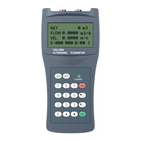
MENU WINDOW DETAILS MENU MENU WINDOW WINDOW DETAILS DETAILS Menu window Function Display POS (positive), NEG (negative) and NET (net) totalizer values. Display signal strength, signal quality and working status Display POS totalizer, instantaneous flow rate, velocity, signal strength, signal quality and working status Display NEG totalizer, instantaneous flow rate, velocity, signal strength, signal quality and working status Display NET totalizer , instantaneous flow rate, velocity, signal strength,... - Page 23 Otherwise, the user needs to configure the 4 transducer parameters. Window for selecting the transducer mounting methods Four methods can be selected: (0) V-method (1) Z-method (2) N-method (3) W-method Display the transducer mounting spacing or distance Entry to store the pipe parameters into the internal NVRAM (non-volatile memory) Entry to read the previously saved pipe parameters Entry to determine whether or not to keep the last correct value when poor...
- Page 24 Window for network communication test Window to set up the schedule-based data saving. Select the items to be saved. Window to set up the schedule for the schedule-based data saving Data output direction control. If ‘To RS-232’ is selected, all the data will be directed to the RS-232 interface If ‘To buffer ‘...
-
Page 25: Trouble Trouble Shooting Shooting
SHOOTING Power-on errors When powered on, the TDS-100H series ultrasonic flowmeter automatically starts the self- diagnosis process to find if there are any hardware and software problems. If a problem is identified, an error message will be displayed. The following table shows the possible error messages, the corresponding causes and their solutions. -
Page 26: O L Utions
The TDS-100H series ultrasonic flowmeter will show an Error Code (a single letter like I, R, etc.) in the lower right corner on menu windows M00 , M01, M02, M03, M90 and M08. When any abnormal Error Code shows, counter-measures should be taken. -
Page 27: Communication Communication Protocol Protocol
3.70 to 3.90 volts. Therefore, the estimated working time is for reference only COMMUNICATION PROTOCOL COMMUNICATION COMMUNICATION PROTOCOL PROTOCOL The TDS-100H series ultrasonic flowmeter integrates a standard RS-232C communication interface and a complete set of communication protocol. - 27 -... -
Page 28: Basic Commands
RS232 Connector Pin-out RS232 RS232 Connector Connector Pin-out Pin-out Definition Not Used Not Used Ring input for connecting a modem 10: RS232 IGU RE WIRING DIAGRAM Communication Protocol Communication Communication Protocol Protocol The protocol is comprised of a set of basic commands that are strings in ASCII format, ending with a carriage (CR) and line feed (LF). - Page 29 C0(CR) C0(CR) C0(CR) OCT open R1(CR) R1(CR) R1(CR) RELAY close R0(CR) R0(CR) R0(CR) RELAY open FOdddd(CR) FOdddd(CR) FOdddd(CR) Force the FO output to output a Fdddd(CR)(LF) frequency of dddd Hz Aoa(CR) Output current a a a at the current A0a a a (CR)(LF) Aoa(CR) Aoa(CR) loop output terminal...
- Page 30 DUMP DUMP DUMP Return the print buffer content In ASCII string format DUMP0 DUMP0 DUMP0 Clear the whole print buffer In ASCII string format DUMP1(CR) DUMP1(CR) DUMP1(CR) Return the whole print buffer In ASCII string Format (24KB content long) Notes: 1.
-
Page 31: Warranty Warranty And And And Service Service
(3) Prefix N The prefix N is a single byte IDN network address, not recommended in a new design. (4) Command binder & The & command binder or connector can connect up to 6 basic commands to form a longer command so that it will make the programming much easier. -
Page 32: Service
receiving written notice of any alleged defect within 10 days after its discovery. Shenitech will determine if the return of the meter is necessary. If it is, the user should be responsible for the one-way shipping fee from the customer to the manufacturer. Teren Instruments is not liable to any defects or damage attributable to miss usage, improper installation, out-of-spec operating conditions, replacement of unauthorized parts and acts of nature. -
Page 33: Abl Es
Pipe Size Tables Pipe Pipe Size Size Tables Tables 8.2.1 8.2.1 8.2.1 Standard Standard Standard Pipe Pipe Pipe size size size charts charts charts for for Copper Copper Copper Classification: Copper tube is classified into four different specification types based on wall thickness for a specific outside diameter. - Page 34 8.2.2 Standard Pipe size charts 8.2.2 8.2.2 Standard Standard Pipe Pipe size size charts charts for for PVC PN 6 6 6 PN 9 9 9 PN 12 PN 18 Wall Wall Wall Wall Wall Wall Wall Wall Wall Wall Wall Wall Convert...
- Page 35 8.2.3 Standard Pipe size charts Steel pipe 8.2.3 8.2.3 Standard Standard Pipe Pipe size size charts charts for for Steel Steel pipe pipe Table A1: Standard ANSI Pipe Size Data for Carbon Steel and Stainless Steel Pipe ANSI B 36.10 ANSI B 36.10 ANSI B 36.19 Nominal...
- Page 36 Table A1: (Continued) Standard ANSI Pipe Size Data for Carbon Steel and Stainless Steel Pipe ANSI B 36.10 ANSI B 36.10 ANSI B 36.19 Nominal Outer Wall Carbon Steel Carbon Steel Stainless Steel Pipe Size Diameter Thickness (in) (in) (in) Wall Schedule Schedule...
- Page 37 Table A1: (Continued) Standard ANSI Pipe Size Data for Carbon Steel and Stainless Steel Pipe ANSI B 36.10 ANSI B 36.10 ANSI B 36.19 Nominal Outer Wall Stainless Carbon Steel Carbon Steel Pipe Size Diameter Thickness Steel (in) (in) (in) Wall Schedule Schedule...
- Page 38 Table A1: (Continued) Standard ANSI Pipe Size Data for Carbon Steel and Stainless Steel Pipe ANSI B 36.10 ANSI B 36.10 ANSI B 36.19 Nominal Outer Wall Carbon Steel Carbon Steel Stainless Steel Pipe Size Diameter Thickness (in) (in) (in) Wall Schedule Schedule...
- Page 39 Table A1: (Continued) Standard ANSI Pipe Size Data for Carbon Steel and Stainless Steel Pipe ANSI B 36.10 ANSI B 36.10 ANSI B 36.19 Nominal Outer Wall Carbon Steel Carbon Steel Stainless Steel Pipe Size Diameter Thickness Wall Schedule Schedule (in) (in) (in)
- Page 40 Table A1: (Continued) Standard ANSI Pipe Size Data for Carbon Steel and Stainless Steel Pipe ANSI B 36.10 ANSI B 36.10 ANSI B 36.19 Nominal Outer Wall Carbon Steel Carbon Steel Stainless Steel Pipe Size Diameter Thickness Wall Schedule Schedule (in) (in) (in)
- Page 41 Table A1: (Continued) Standard ANSI Pipe Size Data for Carbon Steel and Stainless Steel Pipe ANSI B 36.10 ANSI B 36.10 ANSI B 36.19 Nominal Outer Wall Carbon Steel Carbon Steel Stainless Steel Pipe Size Diameter Thickness (in) (in) (in) Wall Schedule Schedule...
- Page 42 Table A1: (Continued) Standard ANSI Pipe Size Data for Carbon Steel and Stainless Steel Pipe ANSI B 36.10 ANSI B 36.10 ANSI B 36.19 Nominal Outer Wall Carbon Steel Carbon Steel Stainless Steel Pipe Size Diameter Thickness Wall Schedule Schedule (in) (in) (in)
- Page 43 Table A1: (Continued) Standard ANSI Pipe Size Data for Carbon Steel and Stainless Steel Pipe ANSI B 36.10 ANSI B 36.10 ANSI B 36.19 Nominal Outer Wall Carbon Steel Carbon Steel Stainless Steel Pipe Size Diameter Thickness (in) (in) (in) Wall Schedule Schedule...
- Page 44 8.2.4 Standard Pipe size charts Cast Iron Pipe 8.2.4 8.2.4 Standard Standard Pipe Pipe size size charts charts for for Cast Cast Iron Iron Pipe Pipe Table A2: Standard Classes of Cast Iron Pipe Class Class Class A A A Class Class Class B B B...
- Page 45 8.2.5 Standard Pipe size charts Ductile Iron Pipe 8.2.5 8.2.5 Standard Standard Pipe Pipe size size charts charts for for Ductile Ductile Iron Iron Pipe Pipe Table A3 Standard Classes of Ductile Iron Pipe Pipe Wall Thickness (in) Nominal Outer Pipe Size Diameter Class...
-
Page 46: Sound Speed Data Of Solids
Sound Speed Tables Sound Sound Speed Speed Tables Tables 8.3.1 8.3.1 8.3.1 Sound Sound Sound Speed Speed Speed data data data of of of solids solids solids Table A4: Sound Speed data of solids Sound Speed Sound Speed Shear Wave(25(d)) Long. - Page 47 Table A4: (Continued) Sound Speed data of solids Sound Speed* Sound Speed* Shear Wave(25(d)) Long.Wave(25(d)) ft/s mm/us in/us Material Iron(Armco) 3,240 10,630 5.90 0.2323 Ductile Iron 3,000 9,843 Cast Iron 2,500 8,203 4.55 0.1791 Monel 2,720 8,924 5.35 0.2106 Nickel 2,960 9,712 5.63...
-
Page 48: Sound Speed In Water
8.3.2 Sound Speed Speed in in in Water Water 8.3.2 8.3.2 Sound Sound Speed Water Table A5: Sound Speed in Water at atmosphere pressure. Unit T (Deg C) V (m/s) T T T V V V T T T V V V T T T V V V T T T... -
Page 49: Sound Speed In Liquids
8.3.3 Sound Speed Speed in in in Liquids Liquids 8.3.3 8.3.3 Sound Sound Speed Liquids Table A6: Sound Speed in Liquids All data given at 25 º C (77 º F) unless otherwise noted. Chemical Kinematic Specific Sound Speed v/ºC Substance Formula Viscosity×10... - Page 50 Table A6: (Continued) Sound Speed in Liquids All data given at 25ºC (77 º F) unless otherwise noted. Kinematic Chemical Specific Sound Speed v/ºC Viscosity×10 Substance Formula Gravity ft/s m/s/ºC 0.992 10.673 Azine 0.982 1,415 4,642.4 (20ºC) (68 ºF) Benzene(29,40, 41) 0.879 1,306 4,284.8...
- Page 51 Table A6: (Continued) Sound Speed in Liquids All data given at 25ºC (77 º F) unless otherwise noted. Kinematic Chemical Sound Speed v/ºC Specific Viscosity×10 Formula Substance Gravity ft/s m/s/ºC Carbon tetrachloride 1.595 3038.1 2.48 0.607 6.531 (33,35,47) (20 ºC) Carbon tetrafluoride(14) 1.75 875.2...
- Page 52 Table A6: (Continued) Sound Speed in Liquids All data given at 25ºC (77 º F) unless otherwise noted. Kinematic Chemical Specific Sound Speed v/ºC Viscosity×10 Formula Gravity Substance ft/s m/s/ºC Diamylamine 1.256 4,120.7 (68 °F) 0.79 1,2Dibromo-ethane(47) 2.18 3,264.4 (20ºC) trans-1,2-Dibromoethene 2.231 3,067.6...
- Page 53 Table A6: (Continued) Sound Speed in Liquids All data given at 25ºC (77 º F) unless otherwise noted. Chemical Kinematic Sound Speed v/ºC Specific Formula Viscosity×10 Substance Gravity ft/s m/s/ºC 2,2-bis(Dif luoromino 1.254 2920 propane( 43) 2,2-Dihydroxydiethyl ether 1.116 1,586 5,2034 Dihydroxyethane 1.113...
- Page 54 Table A6: (Continued) Sound Speed in Liquids All data given at 25ºC (77 º F) unless otherwise noted. Chemical Kinematic Sound Speed v/ºC Specific Formula Viscosity×10 Substance Gravity ft/s m/s/ºC Ether 0.713 3231.6 4.87 0.311 3.346 Ethyl ether 0.713 3231.6 4.87 0.311 3.346...
- Page 55 Table A6: (Continued) Sound Speed in Liquids All data given at 25ºC (77 º F) unless otherwise noted. Chemical Kinematic Sound Speed v/ºC Formula Specific Viscosity×10 Substance Gravity ft/s m/s/ºC 0.125 600.4 Helium(45) 0.025 (-269 ºC) (-269ºC) (-452 °F) 0.684 0.598 6.434 Heptane(22,23)
- Page 56 Table A6: (Continued) Sound Speed in Liquids All data given at 25ºC (77 º F) unless otherwise noted. Kinematic Chemical Specific Sound Speed v/ºC Substance Viscosity×10 Formula Gravity ft/s m/s/ºC 0.81 lsobutanol 1,212 3,976.4 (20ºC) lso-Butane 1,219.8 4002 0.62 lsopentane(36) 3,215.2 0.34 3.658...
- Page 57 Table A6: (Continued) Sound Speed in Liquids All data given at 25ºC (77 º F) unless otherwise noted. Chemical Kinematic Sound Speed v/ºC Specific Formula Viscosity×10 Substance Gravity ft/s m/s/ºC Oil,Diesel 0.80 1,250 4,101 Oil,FueiAA gravity 0.99 1,485 4,872 Oil(Lubricating x200) 1,530 5,019.9 Oil(Oive)
- Page 58 Table A6: (Continued) Sound Speed in Liquids All data given at 25ºC (77 º F) unless otherwise noted. Kinematic Chemical Sound Speed v/ºC Specific Viscosity×10 Formula Substance Gravity ft/s m/s/ºC 1,125 3,691 Phthalardione (152ºC) (306 °F) 1,125 3,691 Phthalic acid,anhydride (152ºC) (306 °F) 1,125...
- Page 59 Table A6: (Continued) Sound Speed in Liquids All data given at 25ºC (77 º F) unless otherwise noted. Chemical Kinematic Sound Speed v/ºC Specific Formula Viscosity×10 Substance Gravity ft/s m/s/ºC 0.992 10.673 Pyridne 0.982 1,415 4,642.4 (20℃) (68 °F) 828.3 2,717.5 Ref rigerant11( 3,4) 1.49...
- Page 60 Table A6: (Continued) Sound Speed in Liquids All data given at 25ºC (77 º F) unless otherwise noted. Chemical Kinematic Sound Speed v/ºC Specific Formula Viscosity×10 Substance Gravity ft/s m/s/ºC 1,1,2,2-Tetrabromo- 2.966 1,027 3,369.4 ethane( 47) 1,1,2,2-Tetrachloro- 1.156 12.438 1.595 1,147 3,763.4 ethane( 67)
- Page 61 Table A6: (Continued) Sound Speed in Liquids All data given at 25ºC (77ºF) unless otherwise noted . Chemical Kinematic Sound Speed v/ºC Specific Formula Viscosity×10 Substance Gravity ft/s m/s/ºC m 1,1,1-Trifluoro-2- Chloro-2-Bromo- HClBrF 1.869 2,273.6 Ethane 1,2,2-Trifluorotrichloro- 783.7 2,571.2 1.563 3.44 ethane(Freon113) CClF...
Need help?
Do you have a question about the TDS-100H and is the answer not in the manual?
Questions and answers