Table of Contents
Advertisement
Advertisement
Table of Contents

Summary of Contents for Xinje OP320
- Page 1 User manual Xinje Electric Co., Ltd. Data No. HOC01 20110705 8.0...
- Page 2 Address: 4 floor, building 7, originality industrial city, JiangSu province, Wuxi, China Post code: 214072 Xinje Electronic Co., Ltd. All rights reserved Without written permission, copy, transfer or use the contents in the manual are forbidden. July, 2011...
-
Page 3: Table Of Contents
1 HARDWARE ..........................3 1-1.I ..............................3 NTRODUCTION 1-2.G ..........................3 ENERAL SPECIFICATIONS 1-3.F ..........................4 UNCTION SPECIFICATIONS 1-3-1.OP320/OP320-S ......................4 1-3-2.OP320-A/OP320-A-N/OP320-A-S ................4 1-3-3.OP325-A/OP325-A-S ....................5 1-3-4.OP330/OP330-S ......................5 1-4.P ................................... 6 1-5.B ............................. 7 UTTON FUNCTION 1-6.P ........................8 ORT AND DOWNLOAD CONNECTION 1-6-1.Port .......................... - Page 4 3-5.K PLC ............................23 SERIES 3-5-1.Connection unit ......................23 3-5-2.Communication parameters ..................24 3-5-3.Cable connection ......................25 3-6.D PLC ........................... 26 ELTA SERIES 3-6-1.Connection unit ......................26 3-6-2.Communication parameters ..................26 3-6-3.Cable connection ......................27 3-7.LG M -K ( PLC ..................27 ASTER PROGRAMMING PORT SERIES...
-
Page 5: Hardware
Hardware 1-1.Introduction OP series operate panel can control the PLC through buttons, texts, lamps. Characteristics: Edit the program in OP20 software, download program via PC serial port Can communicate with various PLCs. Such as Mitsubishi FX series, Omron C series, Siemens S7 series, Koyo SG series and so on ... -
Page 6: 1-3.Function Specifications
English (24 words×4 rows) Font Lattice, vector Button Program 64KB FalshROM Memory Data 1KB SRAM Download RS232 Port OP320: RS232/RS422 communication OP320-S: RS232/RS485 1-3-2.OP320-A/OP320-A-N/OP320-A-S Type Blue LCD Use life Above 20000 hours, temperature 25℃, 24-hour running Display area 192*64 Display Brightness... -
Page 7: 1-3-3.Op325-A/Op325-A-S
1-3-3.OP325-A/OP325-A-S Type Blue LCD Use life Above 20000 hours, temperature 25℃, 24-hour running Display area 192*64 Display Brightness Adjust by potentiometer Text English (24 words×4 rows) Font Lattice, vector Button Program 64KB FalshROM Memory Data 1KB SRAM Download RS232 Port OP325-A: RS232/RS422 communication OP325-A-S: RS232/RS485... -
Page 8: 1-4.Part
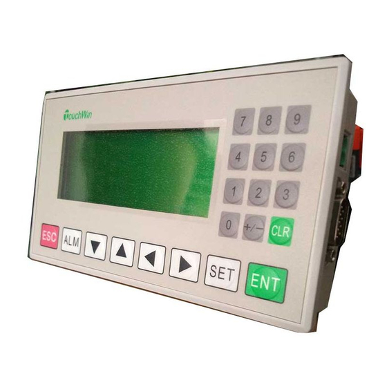
1-4.Part Take OP320-A for example: Display Buttons Power DC24V Buttons Download/COM port Note: (1) There is a potentiometer at the reverse side of OP cover. It can adjust the LCD brightness. Please rotate it with the screw. The LCD backlight will be OFF if there are no any operations for 3 mintues. -
Page 9: 1-5.Button Function
1-5.Button function The buttons on the OP panel can be defined as many functions. They can instead of the buttons on the control machine which has long using life and better touch feeling. Besides, these buttons can be defined to special function such as set on /off bit, screen jump. If no need special functions, the buttons will execute basic functions: set the value of register, reset original screen, page up/down. -
Page 10: 1-6.Port And Download Connection
1-6.Port and download connection 1-6-1.Port OP series has a DB9 port. It can download program and communicate with other devices. OP320, OP320-A, OP320-S, OP320-A-S, OP320-A-N OP325-A, OP330 OP325-A-S, OP330-S Name Name Name 1-6-2.Download connection Please use OP cable to connect OP 9-pin port and PC serial port. The cable can be also used to connect OP and PLC. -
Page 11: 1-7.Dimension And Installation
1-7.Dimension and installation 1-7-1.Dimension Unit: mm OP320, OP320-S 153.0 38.0 33.7 156.5 SET ENT 162.0 OP320-A, OP320-A-N, OP320-A-S 162.2 30.0 25.5 172.0 163.0 OP325-A, OP325-A-S 162.1 34.3 172.0 164.2... -
Page 12: 1-7-2.Installation
OP330, OP330-S 56.5 172.0 164.0 162.0 1-7-2.Installation OP installation diagram: Mounting stand Mounting panel Mounting steps: (1) Make a mounting hole on the mounting panel (2) Put the bottom of OP into the hole (3) Mount the mounting stand into the fixing hole (4) Tighten the 4 screws in the fixing hole Note: 1. -
Page 13: 2-1.Cannot Download Program
Q&A OP program is edited in OP20 software; please refer to OP software manual. This chapter will explain some general questions about using OP. 2-1.Cannot download program 1. The version of hardware and software must be matched. Please see the following table. Hardware version Software version V3.6... -
Page 14: 2-3.Program Security
Contact us if they still cannot communicate. 2-3.Program security OP program cannot be uploaded for security reason. 2-4.Interactive control Please choose “auto change display Screen” and set register address in Tool/Set OP series… Set the register to n, OP will jump to screen No.n when power on. Then the register value will be cleared. -
Page 15: 2-5.Set Data In Sequence
Then you can set these values in sequence. 2-6.Others 1. When choosing Modbus or free format protocol, OP20 will have register 4x, 3x, 1x, 0x. 1x and 3x mean read only. 0x and 4x mean read and write. 2. OP320/OP320-A/OP325/OP330 cannot support RS485. -
Page 16: Plc Connection
Accord with PLC port settings Parity Even parity Even /odd/no parity Accord with PLC port settings Baud rate 19200 4800/38400/9600/115200 Accord with PLC port settings /19200/187500 Station no. 0~255 Default communication parameters of Xinje XC series PLC: 19200, 8, 1, even parity, station no.1. -
Page 17: 3-1-3.Cable Connection
PLC software settings: 3-1-3.Cable connection 1. Direct connect to XC series PLC CPU (RS232 port) XC series PLC CPU RS232 port (PORT1 or PORT2) 9-pin D-type female port 8-pin round port (Diagram 1: fit for OP all series) PLC port:... - Page 18 2. Direct connect to XC series PLC CPU (RS485 port) Xinje XC series PLC CPU 9-pin D-type female port RS485 terminal (PORT2) (Diagram 2— fit for OP320-S, OP320-A-S, OP325-S, OP330-S) 3. Connect PLC via XC-COM-BD (RS232) XC-COM-BD 9-pin D-type female port RS232 8-pin port (Diagram 3—...
-
Page 19: 3-2.Mitsubishi Fx Series Plc
3-2.Mitsubishi FX series PLC 3-2-1.Connection unit Series Connected Port Cable Choose PLC type in OP20 module FX0N FX1N Diagram FX2N RS422 Mitsubishi FX series PLC FX1S FX3U FX3G Diagram RS422 Mitsubishi FX series PLC Diagram RS422 Mitsubishi FX series PLC 3-2-2.Communication parameters OP default settings Series... -
Page 20: 3-2-3.Cable Connection
PLC software settings: 3-2-3.Cable connection 1. FX1N/2N/3U/3G/1S series PLC (RS422) MITSUBISHI PLC FX series CPU RS422 9-pin D-type female port 8-pin round port (Diagram 1— fit for OP320, OP320-A, OP325, OP330)... -
Page 21: 3-3.Siemens S7-200 Series Plc
FX2 series CPU RS422 9-pin D-type female port 25-pin D-type male port (Diagram 2— fit for OP320, OP320-A, OP325, OP330) 3-3.Siemens S7-200 series PLC 3-3-1.Connection unit OP series can communicate with S7-200 series PLC (PPI protocol) via programming port or expansion port. -
Page 22: 3-3-3.Cable Connection
3-3-3.Cable connection S7-200 series PLC RS485 9-pin D-type female port 9-pin D-type male port (Diagram 1— fit for OP320-A-S, OP320-S, OP330-S, OP325-S) 3-4.Omron C series PLC OP can communicate with Omron SYSMAC series CJ/CS/CP/CPM/CQM PLC. Note: 1. CPM1A, CQM1-CPU series CPU don’t have RS232 port, please configure OMRON CIF01 (RS232)adapter with them. -
Page 23: 3-4-2.Communication Parameters
CJ1G-CPU44 CPU RS232 Diagram RS232 CJ1G-CPU45 port CS1H-CPU63/ 64/65/66/67 CS1G-CPU42/ 43/44/45 CS1G-CPU42H CS1G-CPU43H CPU RS232 Diagram CS1G-CPU44H RS232 port CS1G-CPU45H CS1H-CPU63H CS1H-CPU64H CS1H-CPU65H CS1H-CPU66H CS1H-CPU67H C200 C200HE CPU RS232 Diagram RS232 port CPM2A CPM2AE CPM2AH-40CDR-A CPU RS232 Diagram RS232 port Omron CQM1 CQM1-CPU42 CPM/CQM... -
Page 24: 3-4-3.Cable Connection
parameters 4800/38400/9600/115200 Accord with port Baud rate 9600 /19200/187500 parameters Station no. 0~255 The default parameters of Omron CP/CJ/CS series: 9600, 7, 2, even parity, station no.0 (2) Omron CPM/CQM series OP software settings: Parameters Recommend Choices of settings Notes settings PLC type Omron... -
Page 25: 3-5.Koyo Sseries Plc
2. Module CP1W-CIF11 RS485: Module CP1W-CIF11 9-pin D-type female port RS485 terminal (Diagram 2— fit for OP320-A-S, OP320-S, OP330-S, OP325-S) Note: For Omron module CP1W-CIF11, please turn OFF SW1; turn ON SW2, 3, 6; turn ON or OFF SW4. 3. Module CP1W-CIF11 RS422:... -
Page 26: 3-5-2.Communication Parameters
SM24-T SU-6 Diagram 1 RS232 SU-6B RS232 Diagram 1 RS422 Diagram 3 Note: Koyo SH-48RS doesn’t have Run, Stop switch, but only one port (modular plug) Koyo Direct Logic series DL05, DL250 PLC (direct connect to CPU) Series Connected Port Cable Choose correct PLC in module... -
Page 27: 3-5-3.Cable Connection
/19200/187500 Station no. 0~255 The default parameters of Koyo S series PLC: 9600, 8, 1, odd parity, station no.0 PLC software settings: 1. Choose K protocol, station no.1 in the software. 2. Koyo K procotol doesn’t have station no. problem, the communication parameters cannot be changed. -
Page 28: 3-6.Delta Dvp Series Plc
3. RS422 connection: SU-6B, SG-8(G01-DM), SR-21/SR-22(E-02DM-R1), DL250 9-pin D-type port RS422 15-pin SVGA port (Diagram 3— fit for OP320, OP320-A, OP325, OP330) 3-6.Delta DVP series PLC 3-6-1.Connection unit OP can communicate with Delta DVP series PLC through PLC programming port. Connected... -
Page 29: 3-6-3.Cable Connection
2. CPU RS485 port: Delta DVP series PLC CPU 9-pin D-type port RS485 terminal (Diagram 2— fit for OP320-A-S, OP320-S, OP330-S, OP325-S) 3-7.LG Master-K (programming port) series PLC OP can communicate with LG Master-K series PLC. Note: (1) OP can communicate with LG PLC through CPU RS232 port or expansion Cnet module. -
Page 30: 3-7-1.Connection Unit
3-7-1.Connection unit Series Connected Port Cable Choose module LG Master-K80/120-programming Diagram 1 RS232 K120 port 3-7-2.Communication parameters LG Master-K80/120-programming port, OP software settings Parameters Recommend Choices of settings Notes settings PLC type LG Master-K80/120 Choose correct PLC type in Programming port OP20 Port RS232... -
Page 31: 3-7-3.Cable Connection
3-7-3.Cable connection CPU RS232 port: LG Master-K80/120 RS232 9-pin D-type female port 9-pin D-type male port (Diagram 1— fit for OP all series) 3-8.LG Master-K (Modbus) series PLC (multi-function port) 3-8-1.Connection unit Connect through Modbus Rtu protocol Series Connected Port Cable Choose PLC type in OP20 module... -
Page 32: 3-8-3.Cable Connection
Station no. 0~255 The default parameters of LG Master K-Modbus : 9600, 8, 1, even parity, station no.1 PLC settings: Note: (1)Turn on PLC switch BUILT-IN CNET (2)Please choose Modbus Slave protocol RS232 communication 3-8-3.Cable connection 1. LG Modbus Rtu RS232: Controller 9-pin D-type female port 9-pin D-type male port... -
Page 33: 3-9.Lg Master-K (Cnet) Series Plc (Multi-Function Port)
(fit for : OP all series) 2. LG Modbus Rtu RS485: Controller 9-pin D-type female port RS485 terminal (fit for : OP320-A-S, OP320-S, OP330-S, OP325-S) 3-9.LG Master-K (Cnet) series PLC (multi-function port) 3-9-1.Connection unit Expansion Cnet module: Series Connected Port... - Page 34 The default parameters of LG Master K-cnet: 19200, 8, 1, no parity, station no.1 PLC settings Notes: (1)Turn ON switch BUILT-IN CNET of PLC. (2)Please choose special slave procotol. (Cannot choose Modbus slave). RS232 RS485...
-
Page 35: 3-9-3.Cable Connection
(Diagram 1— fit for OP all series) Note: (1)Turn ON switch BUILT-IN CNET of PLC. (2)Choose CNet port when making new PLC program. 2. RS485 connection: Cnet communication module 9-pin D-type port RS485 terminal (Diagram 2— fit for OP320-A-S, OP320-S, OP330-S, OP325-S)... -
Page 36: 3-10.Matsushita Fp Series Plc
3-10.Matsushita FP series PLC OP can communicate with Matsushita FP series PLC through programming port or expansion port. 3-10-1.Connection unit Series Connected Port Cable Choose PLC type in module OP20 Diagram 1 RS232 FP-M RS232 Diagram 1 FP-X Diagram 1 RS232 FP∑... -
Page 37: 3-10-3.Cable Connection
PLC settings Note: (1) Please set the PLC register like this in OP software: (2)Make sure the PLC switch is turn to PPOG (3)The PLC must RUN when communicating with OP. (4)Do not choose general communication mode when setting the PLC parameters, otherwise, the communication will be error. - Page 38 3. CPU RS422: Matsushita mewnet-FP series FP1 CPU RS422 9-pin D-type female port 8-pin male port (Diagram 3— fit for OP320, OP320-A, OP325, OP330) 4. CPU 15-pin port: PLC RS422 9-pin D-type female port 15-pin D-type male port (Diagram 4— fit for OP320, OP320-A, OP325, OP330)...
-
Page 39: 3-11.Schneider Neza Series Plc
3-11.Schneider NEZA series PLC OP can communicate with Schneider NEZA PLC through programming port. (Modbus protocol) 3-11-1.Connection unit Series Connected Port Cable Choose PLC type in OP20 module Micro TSX 37-05 RS485 Diagram 1 TSX 37-08 TSX 37-10 TSX 37-21/22 Schneider Twido Twido... - Page 40 PLC software settings: Note: 1. The register of Twido is dynamic managed. Please add a sentence at the end of PLC program to avoid communication error. 2. To open the bit address range, you have to make a program as below. For example: drive a coil of %M127, all the addresses before %M127 can do data switching.
-
Page 41: 3-11-3.Cable Connection
1. CPU RS485: Schneider Micro/NEZA/Twido series TSX-37, TSX-07, Twido series CPU 9-pin D-type female port 8-pin male port (Diagram 1— fit for OP320-A-S, OP320-S, OP330-S, OP325-S) 2. M238 CPU: Schneider Micro series CPU 9-pin D-type female port RJ-45 port (Diagram 2— fit for OP320-A-S, OP320-S, OP330-S, OP325-S)... -
Page 42: 3-12-2.Communication Parameters
26MCT/36MCT RS485 Diagram 2 RS232 Diagram 3 20MA FB-DTBR/ FB -MA 28MA RS232 Diagram 4 DTBR-E module 40MA RS485 Diagram 5 Note: For MA series CPU, please transform the com port to RS232 or RS485 through FB-DTBR or FB-DTBR-E module. 3-12-2.Communication parameters OP software settings Parameters... - Page 43 20MC, 28MC, 40MC, 19MCT, 26MCT, 36MCT series CPU RS485 9-pin D-type female port 15-pin D-type male port (Diagram 2— fit for OP320-S, OP320-A-S, OP325-S, OP33-S) 3. FB-DTBR/DTBR-E module RS232: 20MA, 28MA, 40MA series FB-DTBR /DTBR-E module RS232 9-pin D-type female port 15-pin D-type male port (Diagram 3—...
-
Page 44: 3-13.Vigor Vb Series Plc
20MA, 28MA, 40MA series FB-DTBR /DTBR-E module RS485 9-pin D-type female port 3-pin terminal (Diagram 5 — fit for OP320-S, OP320-A-S, OP325-S, OP33-S) 3-13.Vigor VB series PLC OP can communicate with Vigor VB series PLC (including VB0, VB1,VB2) through CPU programming port. -
Page 45: 3-13-2.Communication Parameters
VB2-16M Diagram 4 RS485 VB2-32M VH -14MR RS232 Diagram 1 3-13-2.Communication parameters OP software settings Parameters Recommend Choices of settings Note settings PLC type Vigor series Choose correct PLC type in OP20 Port RS232 RS232/RS485/RS422 Data bit Accord with PLC port parameters Stop bit Accord with PLC port parameters Parity... -
Page 46: 3-14.Emerson Ec20 Series Plc
(Diagram 3— fit for OP320, OP320-A, OP325, OP330) (2) RS485 connection VIGOR VB series RS485 expansion card RS485 9-pin D-type female port 5-wire terminal (Diagram 4 — fit for OP320-S, OP320-A-S, OP325-S, OP33-S) 3-14.Emerson EC20 series PLC 3-14-1.Connected unit Connected Series Port... -
Page 47: 3-14-2.Communication Parameters
3-14-2.Communication parameters OP software settings Parameters Recommend Choices of settings Note settings PLC type Emerson Choose correct PLC type in OP20 EC20 series Port RS232 RS232/RS485 Data bit Accord with PLC port parameters Stop bit Accord with PLC port parameters Parity Even parity Even / odd / no parity... -
Page 48: 3-15.Idec Micro Smart Series Plc
9-pin D-type female port 5-wire terminal (Diagram 3— fit for OP320-S, OP320-A-S, OP325-S, OP33-S) Note: Emerson EC20 series PLC COM1 has RS232 and RS485. Only one of them can be used at the same time. Do not connect unused com to avoid interference. -
Page 49: 3-16.Keyence Kv Series Plc
2. IDEC CPU(Micro3C series)RS232: Idec PLC Micro3C CPU RS232 programming port 9-pin D-type female port 8-pin round male port (fit for OP all series) 3-16.Keyence KV series PLC Keyence KV series PLC CPU RS232 port: Keyence KV-10/16/24/40 series PLC CPU RS232 9-pin D-type female port 6-pin RJ-11 port (fit for OP all series)... -
Page 50: 3-17.Saia-Burgess Pcd Series Plc
3-17.SAIA-Burgess PCD series PLC SAIA-Burgess PCD series PLC RS232 port: SAIA-Burgess PCD series PLC RS232 9-pin D-type female port 9-pin D-Sub port (fit for OP all series)... - Page 51 XINJE Electric Co., Ltd. 4th Floor, Building 7th, No.100 Dicui Rd, Wuxi, China Tel: 86-0510-85134139 Fax: 86-0510-85111290 www.xinje.com Email: cheerfiona@gmail.com...
Need help?
Do you have a question about the OP320 and is the answer not in the manual?
Questions and answers
Language change kaise kare