
Summary of Contents for GE Multilin F650
- Page 1 Grid Solutions F650 Digital Bay Controller Instruction Manual Firmware version: 7.5x EnerVista F650 Setup version: 7.5x GE publication code: GEK-106310-AF *GEK-106310AF*...
- Page 2 The contents of this manual are the property of GE Multilin Inc. This documentation is furnished on license and may not be reproduced in whole or in part without the permission of GE Multilin. The content of this manual is for informational use only and is subject to change without notice.
-
Page 3: Table Of Contents
EnerVista 650 Setup software ..............1-14 1.3.1 System requirements......................1-14 1.3.2 Installation..........................1-14 1.3.3 Connecting EnerVista 650 Setup to the F650 ............1-18 1.3.3.1 Configuring an Ethernet connection ..................1-18 1.3.3.2 Configuring the RS232 connection..................1-18 650 hardware ....................1-19 1.4.1 Mounting & wiring........................1-19 1.4.2... - Page 4 EnerVista 650 Setup menu....................4-10 4.1.6 File menu ..........................4-11 4.1.6.1 New, Open, Save, Save as, and Close ..................4-12 4.1.6.2 Configuration file converter.......................4-13 4.1.6.3 Properties ............................4-15 4.1.6.4 Print options............................4-15 4.1.6.5 Compare to settings file ......................4-16 4.1.6.6 PLC checksum calculation ......................4-16 F650 DIGITAL BAY CONTROLLER GEK-106310-AF...
- Page 5 4.2.7.3 All events screen ..........................4-59 4.2.7.4 New events screen........................4-61 4.2.7.5 Alarms panel ............................ 4-62 4.2.7.6 Input/output monitoring screen ..................... 4-63 Web server...................... 4-66 4.3.1 Home............................4-66 4.3.2 Snapshot events ........................4-67 4.3.3 Control events........................4-68 4.3.4 Alarms............................4-69 4.3.5 Oscillography .........................4-70 GEK-106310-AF F650 DIGITAL BAY CONTROLLER...
- Page 6 5.4.1.2.1 Single setting group ......................5-44 5.4.1.2.2 Multiple setting groups ....................5-45 5.4.2 Inverse time curve characteristics ................5-47 5.4.2.1 IEEE curves ............................5-48 5.4.2.2 IEC curves............................5-49 5.4.2.3 IAC curves ............................5-51 5.4.2.4 ANSI curves ............................5-52 5.4.2.5 I2t curves............................5-54 5.4.2.6 Definite time curves........................5-54 F650 DIGITAL BAY CONTROLLER GEK-106310-AF...
- Page 7 5.5.3.3 Autoreclose internal status .....................5-114 5.5.3.4 General autoreclose staus diagram ...................5-115 5.5.3.5 Logic for blocking protection functions during reclose cycle.........5-116 5.5.4 Breaker failure element (50BF) ...................5-118 5.5.5 VT fuse failure element (VTFF) ..................5-121 5.5.5.1 Fuse failure algorithm........................5-121 GEK-106310-AF F650 DIGITAL BAY CONTROLLER...
- Page 8 5.10.3.1 Create new project ........................5-181 5.10.3.2 Create equation ...........................5-181 5.10.3.3 Add input to automation......................5-181 5.10.3.4 Add output to automation ......................5-182 5.10.3.5 Add digital operation .........................5-182 5.10.3.6 Link inputs, outputs, and operations ..................5-182 5.10.3.7 Add library ............................5-182 F650 DIGITAL BAY CONTROLLER GEK-106310-AF...
- Page 9 6.2.12.3 Oscillography........................... 6-32 6.2.12.4 Data logger............................6-33 6.2.12.5 Demand.............................. 6-33 6.2.12.6 Energy..............................6-33 6.2.12.7 Breaker maintenance ........................6-34 6.2.13 IEEE 1588 precision time protocol (PTP)..............6-35 6.2.14 Versions ............................6-35 6.2.15 Redundancy ...........................6-37 Metering ......................6-38 6.3.1 Primary values........................6-38 GEK-106310-AF F650 DIGITAL BAY CONTROLLER...
- Page 10 Remote inputs ..........................7-4 7.1.5 Remote outputs ........................7-5 7.1.5.1 DNA bit pairs ............................7-5 7.1.5.2 UserSt bit pairs........................... 7-6 IEC 61850 profile for F650 ................7-7 7.2.1 Overview .............................7-7 7.2.1.1 Scope and outline of IEC 61850....................7-8 7.2.2 Communication profiles ......................7-9 7.2.3...
- Page 11 Summary of main steps....................9-20 9.1.4.1 Boot code upgrade (*)........................9-20 9.1.4.2 Firmware upgrade(*) ........................9-21 Firmware upgrade version 7.00 or above..........9-22 9.2.1 Communication parameters ..................9-22 9.2.2 Firmware version upgrade ....................9-23 9.2.2.1 Introduction ............................9-23 GEK-106310-AF F650 DIGITAL BAY CONTROLLER...
- Page 12 11.1.3 Set the protection function ..................... 11-3 11.1.4 Test ............................. 11-4 11.2 Example 2: TOC protection & reclosing settings........11-5 11.2.1 Description..........................11-5 11.2.2 Communicate with the relay..................11-5 11.2.3 Set the protection function ..................... 11-5 1-10 F650 DIGITAL BAY CONTROLLER GEK-106310-AF...
- Page 13 13 F650 13.1 Symptoms and recommended actions............13-1 TROUBLESHOOTING GUIDE A LOGIC OPERANDS A.1 Operands - F650 - model FX - GX ..............A-1 B MODBUS PROTOCOL Introduction ..................... B-1 B.2 MODBUS F650 ....................B-2 B.2.1 Implemented MODBUS functionality ................B-2 B.2.2...
- Page 14 Configuring DNP user map ....................C-13 C.5.2 Example of custom binary input points map ............C-15 C.5.3 Multiple DNP 3.0 masters communication with F650 ........C-16 C.6 Binary output and control relay output ............C-18 C.7 Binary counters ....................C-19 C.8 Analog inputs ....................C-20 D IEC 60870-5-104 D.1 Introduction .....................
-
Page 15: Getting Started
GETTING STARTED 1.1 Important procedures Use this chapter for initial setup of your new F650 Digital Bay Controller. 1.1.1 Cautions and warnings To help ensure years of trouble free operation, please read through the following chapter for information to help guide you through the initial installation procedures of your new relay. -
Page 16: General Cautions And Warnings
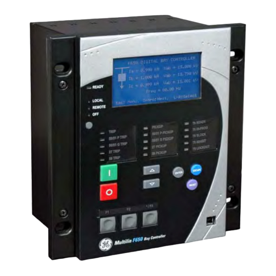
This product is rated to Class A emissions levels and is to be used in Utility, Substation Industrial environments. Not to be used near electronic devices rated for Class B levels. Figure 1-1: Front view of F650 unit F650 DIGITAL BAY CONTROLLER... -
Page 17: Communication Board Withdrawal/Insertion
Check that the relay is fully operative. Figure 1-1: Module withdrawal/insertion GE Multilin will not be responsible for any damage to the relay, connected equipment or personnel whenever these safety rules are not followed. -
Page 18: Magnetic Module Terminals
It is very important, for safety reasons, not to change or switch the terminals for CTs and VTs. Figure 1-1: Rear view of F650 unit GE Multilin will not be responsible for any damage of the relay, connected equipment or personnel whenever these safety rules are not followed. -
Page 19: Inspection Checklist
GE EnerVista™ DVD (includes the EnerVista 650 Setup software and manuals in PDF format) • Wiring diagram. • Certificate of Compliance For product information, instruction manual updates, and the latest software updates, please visit the GE Multilin Home Page: http://www.gegridsolutions.com/multilin GEK-106310-AF F650 DIGITAL BAY CONTROLLER... - Page 20 Should you wish to receive additional information, or for any particular problem that cannot be solved by referring to the information contained herein, please contact General Electric, Grid Solutions. F650 DIGITAL BAY CONTROLLER GEK-106310-AF...
-
Page 21: Safety Instructions
When using a laptop, it is recommended that the power supply be disconnected. In many cases the laptop may not be correctly grounded either due to the power supply or to the connector cables used. GE Multilin will not be responsible for any damage to the relay or connected equipment when this basic safety rule is not followed. -
Page 22: General Safety Instructions
Before working on CTs, they must be short circuited. • Do not remove the voltage terminal blocks or disconnect the voltage input wires when the voltage phases are live. The voltage inputs must be de-energized prior to any servicing. F650 DIGITAL BAY CONTROLLER GEK-106310-AF... -
Page 23: Warning Symbols
Earth (Ground) Terminal. Terminal de terre (masse). Protective Earth Terminal. Terminal de terre de protection. Note: Read all instructions included in package before using your product. Additional safety information Product Safety Supplement document available at; http://www.gegridsolutions.com/ProductSafety/ GEK-106310-AF F650 DIGITAL BAY CONTROLLER... -
Page 24: Overview
1.2.2 Hardware architecture 1.2.2.1 F650 basic design The 650 is a digital-based device containing a central processing unit (CPU) that handles multiple types of input and output signals. The 650 family can communicate over a local area network (LAN) with an operator interface, a programming device, or another 650 device. -
Page 25: F650 Signal Type
CHAPTER 1: GETTING STARTED 1.2 OVERVIEW 1.2.2.2 F650 signal type Contact Inputs/Outputs: Digital signals. CT and VT inputs: Signals coming from the inputs of current and voltage transformers, used for monitoring the power system signals. Remote CAN Bus Inputs/Outputs: Signals associated with physical input/output contacts from a Remote Digital Input/ Output Module (CIO) connected to the 650 unit via the CAN Bus existing in options X, Y, Z, C and M for rear serial communication board 1. - Page 26 CAN Bus I/Os. This provides increased communication speed, and acknowledgement of modules, abnormalities, etc. As this is a serial port supporting a communications protocol, it provides immunity against external or internal disturbances. 1-12 F650 DIGITAL BAY CONTROLLER GEK-106310-AF...
-
Page 27: Protection
PROTECTION CAN I/O INTERNAL SERIAL MULTIPLEXED SERIAL COM 2 COM H MEASUREMENT PROCESSOR ANALOG SERIAL INPUTS COM2 COM H CURENT AC FRONT VOLTAGE AC HUMAN MACHINE INTERFACE SERIAL PORT Figure 1-1: Communications architecture (B6816F2) GEK-106310-AF F650 DIGITAL BAY CONTROLLER 1-13... -
Page 28: Enervista 650 Setup Software
Click Install Now and follow the installation instructions to install the complimentary EnerVista software. When installation is complete, start the EnerVista Launchpad application. Click IED Setup in the Launch Pad window. Figure 1-2: Launchpad window 1-14 F650 DIGITAL BAY CONTROLLER GEK-106310-AF... - Page 29 1.3 ENERVISTA 650 SETUP SOFTWARE Click Add Product and select the “F650 Bay Controller” relay from the Install Software window as shown below. Select the “Web” option to ensure the most recent software release, or select “CD” if you do not have a web connection, then click Add Now to list software items for the F650.
- Page 30 The default program group containing the application is added to as shown in the Selected Program Folder window. Click Next to begin the installation process, and all the necessary program files are copied into the selected directory. Figure 1-6: Select program folder 1-16 F650 DIGITAL BAY CONTROLLER GEK-106310-AF...
- Page 31 10. To complete the installation, select the desired language for startup. Figure 1-7: Language window 11. Click Finish to end the installation. The F650 device has been added to the list of installed IEDs in the EnerVista Launchpad window, as shown below.
-
Page 32: Connecting Enervista 650 Setup To The F650
1.3 ENERVISTA 650 SETUP SOFTWARE CHAPTER 1: GETTING STARTED 1.3.3 Connecting EnerVista 650 Setup to the F650 This section is intended as a quick start guide to using the EnerVista 650 Setup software. Refer to section 4.1 in this manual for more information about the EnerVista 650 Setup software interface. -
Page 33: Hardware
USB port a male A / male B USB shielded wire is needed To communicate via the F650 rear RS485 port from a PC RS232 port, the GE Multilin RS232/RS485 converter box is required. This device (catalog number F485) connects to the computer using a “straight-through” serial cable. A shielded twisted-pair (20, 22 or 24 AWG according to American standards;... -
Page 34: Faceplate Display
Figure 1-2: RS485 connection for 650 units To communicate through the F650 rear Ethernet port from a PC, a crossover cable is required. If the connection is performed through a hub or a switch, a direct Ethernet cable is required. -
Page 35: Maintenance
This maintenance can involve in-service, out-of-service, or unscheduled maintenance. If it is concluded that the relay or one of its modules is of concern, contact GE Multilin or one of its representative for prompt service. -
Page 36: Repairs
1.4.7 Disposal The F650 is intended to be part of defective large-scale stationary industrial tools and large-scale fixed installations. This product cannot be disposed of as unsorted municipal waste in the European Union. For proper recycling return this product to your supplier or a designated collection point. For more information go to www.recyclethis.info. -
Page 37: Product Description
PRODUCT DESCRIPTION 2.1 F650 Overview F650 is a protection, control, monitoring, metering and registering unit, suitable for many different applications, such as main protection for distribution feeders and transmission lines, as well as backup protection for transformers, busbars, capacitor banks, etc. -
Page 38: Description
High-availability Seamless Redundancy (HSR) of IEC 62439-3 (clause 4 (PRP) and clause 5 (HSR)) for firmware version 7.00 and so on. Rear port COM1 can be set to support IEC60870-5-103 protocol The F650 IEDs use flash memory technology which allows field upgrading as new features are added: Figure 2-1: FUNCTIONAL BLOCK DIAGRAM F650 DIGITAL BAY CONTROLLER... -
Page 39: Ansi Device Numbers And Functions
Broken Conductor 81df/dt Frequency Rate of Change VTFF VT Fuse Failure Detection 60CTS Failure Current Transformer Failure ** 2nd Harmonic Second Harminic Inhibit ** Inhibit ** These functions are available for firmware version 7.50 or above GEK-106310-AF F650 DIGITAL BAY CONTROLLER... -
Page 40: Other Device Functions
Configurable One-Line Diagram (Graphic Snapshot Events (up to 1023)** Web Server Application model only) Phasor Diagram (available in EnerVista 650 Setup) ** Maximum number of events can vary depend on firmware version. See details in section 2.5.3.3 F650 DIGITAL BAY CONTROLLER GEK-106310-AF... -
Page 41: Order Codes
2.4 ORDER CODES 2.4 Order codes F650 units are supplied as ½ 19” rack, 6 units high, containing the following modules: power supply, CPU, I/O modules, communication modules. The required information to completely define an F650 model is shown on Table 2–1:... - Page 42 (7) Chinese Language: This language is not supported for Rear Ethernet Communication Board options: G, H, J,K,L or M (8) Display option with RS232 is not available for F650 Models with Rear Ethernet Communication Board 2 options from G to M or with...
-
Page 43: Cio Modules
(Remote CAN bus I/O module) for using up to 2 additional boards. F650 units allow monitoring and configuring these I/O boards as if they were internal boards, located on slots F and G. In this case, slots are labeled as H and J. -
Page 44: Technical Specifications
Timing Accuracy: ..............Operate at > 1.03 times the pickup ±3% of operate time or 50 ms (whichever is greater) Voltage Restraint: ..............selectable by setting Saturation Level: ...............48 times the pickup level Snapshot Events: ..............selectable by setting F650 DIGITAL BAY CONTROLLER GEK-106310-AF... - Page 45 Reset Type: ................. instantaneous or time delayed, according to IEEE Timing Accuracy:..............Operate at > 1.03 times the pickup ±3% of operate time or 50 ms (whichever is greater) Saturation Level: ..............48 times the pickup level Snapshot Events: ..............selectable by setting GEK-106310-AF F650 DIGITAL BAY CONTROLLER...
- Page 46 Operate Time: ................< 50 ms at 3 x pickup at 50 Hz, typically Timing Accuracy: ..............at 0 ms time delay (no intentional delay): 50 ms at non-zero time delay: ±3% of operate time or 50 ms (whichever is greater) Snapshot Events: ..............selectable by setting 2-10 F650 DIGITAL BAY CONTROLLER GEK-106310-AF...
- Page 47 Reset Type: ................. instantaneous or time delayed, according to IEEE Timing Accuracy:..............Operate at > 1.03 times the pickup ±3% of operate time or 50 ms (whichever is greater) Saturation Level: ..............48 times the pickup level Snapshot Events: ..............selectable by setting GEK-106310-AF F650 DIGITAL BAY CONTROLLER 2-11...
- Page 48 Characteristic Angle:...............-90º to +90º in steps of 1º Block Logic: .................permission or block selectable by setting Angle Accuracy: ................±2º for I > 0.1 A and V > 5 Vac Operate Time: ................< 30 ms, typically 2-12 F650 DIGITAL BAY CONTROLLER GEK-106310-AF...
- Page 49 Trip Delay: ................... 0.00 to 900.00 s in steps of 0.01 s Reset Delay: ................0.00 to 900.00 s in steps of 0.01 s Timing Accuracy:..............±3.5% of operating time or 50 ms (whichever is greater) Snapshot Events: ..............selectable by setting GEK-106310-AF F650 DIGITAL BAY CONTROLLER 2-13...
- Page 50 Reset Delay: ................0.00 to 900.00 s in steps of 0.01 s Minimum Voltage Threshold: ..........10 to 300 V in steps of 1 V Time Delay Accuracy:............0 to 7 cycles Operate Time: ................typically 10 cycles at 0.1 Hz/s change Snapshot Events: ..............selectable by setting 2-14 F650 DIGITAL BAY CONTROLLER GEK-106310-AF...
- Page 51 Curve Multiplier (Time Dial): ..........0.02 to 2.00 s in steps of 0.01 s Tripping Time Accuracy: ............±3.5% of operate time or 50 ms whichever is greater Snapshot Events: ..............selectable by setting Operate Time:................< 45 ms at 50 Hz, typically GEK-106310-AF F650 DIGITAL BAY CONTROLLER 2-15...
-
Page 52: Control
±0.5% of the reading ± 10 mA from 0.05 to 10.00 A ±1.5% of the reading for higher values Timing Accuracy: ..............±3.5% of operate time or 50 ms (whichever is greater) Snapshot Events: ..............selectable by setting 2-16 F650 DIGITAL BAY CONTROLLER GEK-106310-AF... - Page 53 Overload Factor: ..............0 to 10000000 in steps of 1 Board Origin: ................all available input/output boards in the device. See order code (F, G, H, J) Input Origin:................up to 32 (depending on board selection type) GEK-106310-AF F650 DIGITAL BAY CONTROLLER 2-17...
- Page 54 Tripping Time Accuracy: ............±250 ms or 5% (whichever is greater) Full Load Amps: .................0.5 to 10.0 A in steps of 0.1 A Breaker Supervision: ...............selectable by setting Min. Stop Time: ................0.0 to 900.0 s in steps of 0.1 s 2-18 F650 DIGITAL BAY CONTROLLER GEK-106310-AF...
-
Page 55: Monitoring
(fault location), line parameters, recloser and breaker status information. Data Storage:................In non-volatile (flash) memory without battery available through communications In volatile (RAM) memory available through HMI (if selectable by setting) Format: ..................text in ASCII format GEK-106310-AF F650 DIGITAL BAY CONTROLLER 2-19... - Page 56 Trigger Input: ................selectable by setting (operation mode selection for the block interval calculation method) Snapshot Events: ..............selectable by setting DATA LOGGER Number of Channels:..............1 to 16 Parameters:.................any available analog actual value Samples: ..................1 second, 1, 5, 10, 15, 20, 30, 60 minutes Storage Capacity:..............fixed, 32768 measurements 2-20 F650 DIGITAL BAY CONTROLLER GEK-106310-AF...
-
Page 57: User-Programmable
(basic and mimic). The metering screen contains current and voltages for phases and ground in primary or secondary values. USER-PROGRAMMABLE FRONT KEYS Number of Configurable Keys:.......... 5 Operation: ................... Drive PLC operands GEK-106310-AF F650 DIGITAL BAY CONTROLLER 2-21... -
Page 58: Metering
AC CURRENT INPUTS CT Ratio:..................1.0 to 6000.0 in steps of 0.1 Rated Currents:................Appropriate for 1 or 5 A. F650 has universal range for CT (valid for 1 or 5 A to only one terminal). Relay Burden:................< 8 mVA at 1 A <... - Page 59 Minimum Input Voltage: ............2.4 V Maximum Input Voltage: ............± 24 V Formats: ..................B000 (*) B001, B002 and B003 (* (*) Signal combinations recognized in accordance with IRIG Standard 200-95 Isolation:..................2 kV GEK-106310-AF F650 DIGITAL BAY CONTROLLER 2-23...
-
Page 60: Real Time Clock
120 to 230 V Size: 5 x 20 mm Min/Max AC Voltage: 102 / 250 V Type: Quick acting (F) Voltage Loss Hold-up Time: 200 ms typical UL listed miniature Fuse 100 ms worst case 2-24 F650 DIGITAL BAY CONTROLLER GEK-106310-AF... -
Page 61: Communications
PRP, 1588, 10/100 Base TX* + Redundant 100 Base TX Model M: PRP, HSR, RSTP, 1588, 10/100 Base TX* + Redundant 100 Base TX (*) Note: This Ethernet port (ETH_E) is intended only for maintenance purposes. GEK-106310-AF F650 DIGITAL BAY CONTROLLER 2-25... - Page 62 PARALLEL REDUNDANCY PROTOCOL (HSR) (IEC 62439-3 CLAUSE 5, 2012) Ethernet ports: A and B Networks: 10/100 MB Ethernet RAPID SPANNING TREE PROTOCOL (RSTP) (IEC 62439-1, IEEE 801.2D) Ethernet ports: A and B Networks: 10/100 MB Ethernet 2-26 F650 DIGITAL BAY CONTROLLER GEK-106310-AF...
-
Page 63: Optical
At the Beginning of Life (BOL). Over the specified operating temperature and voltage ranges. All conditions for Note 3 apply except that the measurement is made at the center of the symbol with no window time-width. GEK-106310-AF F650 DIGITAL BAY CONTROLLER 2-27... -
Page 64: Environmental
40˚C @ 93% R.H. Type test report available upon request. F650 has been designed to comply with the highest existing requirements. More specifically, UNIPEDE recommendations for high voltage substations are followed, even if for most applications such high classes are not required. -
Page 65: Approvals
The EAC Technical Regulations (TR) for Machines and Equipment apply to the Customs Union (CU) of the Russian Federation, Belarus, and Kazakhstan Item Description Country of origin Spain Date of manufacture See label on the F650 unit Declaration of Conformity and/or Certificate of Conformity Available on request GEK-106310-AF F650 DIGITAL BAY CONTROLLER 2-29... -
Page 66: External Connections
2.6 EXTERNAL CONNECTIONS CHAPTER 2: PRODUCT DESCRIPTION 2.6 External connections Figure 2-2: F650 wiring diagram (189C4216H2) 2-30 F650 DIGITAL BAY CONTROLLER GEK-106310-AF... - Page 67 79 INITIATE I SENS RECLOSE F14 + CC8 F15 + COIL 2 52/a SUPERVISION TRIP F17 + COIL 2 52/b SUPERVISION F18 - 52/b Figure 2-3: Input/output configurations for boards F1 and F2 (189C4216H1) GEK-106310-AF F650 DIGITAL BAY CONTROLLER 2-31...
- Page 68 2.6 EXTERNAL CONNECTIONS CHAPTER 2: PRODUCT DESCRIPTION 2-32 F650 DIGITAL BAY CONTROLLER GEK-106310-AF...
-
Page 69: Hardware
Grid Solutions F650 Digital Bay Controller Chapter 3: Hardware HARDWARE 3.1 Module description Digital Optional Power Transformer Module Module Digital Supply SCREEN RS232 RS232 Figure 3-1: Block diagram GEK-106310-AF F650 DIGITAL BAY CONTROLLER... - Page 70 3.1 MODULE DESCRIPTION CHAPTER 3: HARDWARE F650 units incorporate the following modules: • Power supply, which can be simple or redundant, depending on the selected model • Front module with alphanumerical (4 x 20) or optional graphical (16 x 40 characters) display. It includes the bus on its rear, which communicates with the rest of modules via a high speed CAN bus.
-
Page 71: Power Supply
3.2 POWER SUPPLY 3.2 Power supply F650 can incorporate a simple or redundant power supply. The main and backup modules are identical. Control power supplied to the relay must be connected to the matching power supply range of the relay. If the voltage is applied to the wrong terminals, damage can occur. -
Page 72: Mechanical Description
The front keypad, display, and communications port are easily access on the front of the unit. The wiring is at the rear of the unit. Drilling dimensions are shown on Figure 3-3: Cutout and drilling dimensions Figure 3-2: Panel mount The relay width allows the mounting of two units on a standard 19’’ panel, 8 units high. F650 DIGITAL BAY CONTROLLER GEK-106310-AF... -
Page 73: Gek-106310-Af F650 Digital Bay Controller
CHAPTER 3: HARDWARE 3.3 MECHANICAL DESCRIPTION 1.10 (28) 6.80 (172,8) 0.75 (19,1) 9.33 (237) 8.39±0.039 (213±1) 0.47 (12) 7.44 (189) 0.47 (12) Figure 3-3: Cutout and drilling dimensions GEK-106310-AF F650 DIGITAL BAY CONTROLLER... - Page 74 3.3 MECHANICAL DESCRIPTION CHAPTER 3: HARDWARE Figure 3-4: 19” rack dimensions 8U high for two relays F650 DIGITAL BAY CONTROLLER GEK-106310-AF...
-
Page 75: Rear Description
As a minimum, 96 strands of number 34 AWG should be used. The communication boards have different types of connector depending on the selected media: RS485, glass or plastic fiber optic. Figure 3-5: Connector locations GEK-106310-AF F650 DIGITAL BAY CONTROLLER... - Page 76 It is very important, for safety reasons, not to change or switch the terminals for CTs and VTs. F650 DIGITAL BAY CONTROLLER GEK-106310-AF...
-
Page 77: Gek-106310-Af F650 Digital Bay Controller
Special care is required when disconnecting CT wire leads from the terminal block. A high voltage potential can occur if a wire is disconnected while a CT is energized. CT isolation or de-energization is required prior to CT terminal wire removal. GEK-106310-AF F650 DIGITAL BAY CONTROLLER... -
Page 78: Wiring
3.4 WIRING CHAPTER 3: HARDWARE 3.4 Wiring 3.4.1 External connections F650 units can have different options for the F module: Option 1: Board with 16 digital inputs and 8 outputs. Option 2: Board with 8 digital inputs, 4 circuit supervision inputs, 6 conventional outputs, and two current sensing... -
Page 79: Cable/Fiber Ethernet Board
In models C and D (options for versions prior to 7.00), the 10/100BaseTx port is selected by an internal switch. This switch must be configured as shown in the figure 3-8 in order to select between fiber or cable. Figure 3-8: Fiber/cable selection GEK-106310-AF F650 DIGITAL BAY CONTROLLER 3-11... -
Page 80: Transceiver Optical Power Budget Vs. Link Length
OPB also provides a margin for link aging and unplanned losses due to cable plant reconfiguration and repair. OPB (dB) Fiber optic Cable length (km) 62.5/125 μm 50/125 μm 11.4 10.9 10.5 3-12 F650 DIGITAL BAY CONTROLLER GEK-106310-AF... -
Page 81: Interfaces, Settings & Actual Values
In online mode, real-time communication with the device is supported. The EnerVista 650 Setup software, provided with every F650 relay, can be run from a computer supporting Microsoft Windows XP(SP 2 or 3), Windows 7 or Windows 8. This chapter provides a summary of the basic EnerVista 650 Setup software interface features. -
Page 82: Viewing Actual Values
4.1.1.4 Firmware upgrades The firmware of a F650 device can be upgraded, locally or remotely, via the EnerVista 650 Setup software. Instructions are provided in Chapter 9: Bootcode and firmware upgrade. -
Page 83: Main Screen
The EnerVista 650 Setup software main window includes the following components: • Title bar • Main menu bar • Main icon bar • Working area • Status bar Title Working Area Figure 4-1: EnerVista 650 Setup main screen GEK-106310-AF F650 DIGITAL BAY CONTROLLER... -
Page 84: Connect To The Relay
Modbus/TCP Setup (if ModBus /TCP is selected as control type): Communication parameters for ModBus TCP communication. • Communication control: Device communication status (communicating or not communicating). • Communication optimization: allows optimizing the communication time outs and failure establishing. F650 DIGITAL BAY CONTROLLER GEK-106310-AF... -
Page 85: Computer Settings
These parameters are the maximum time to wait for a response in the relay (in ms) and the maximum number of connection attempts to perform before assuming communications failure. GEK-106310-AF F650 DIGITAL BAY CONTROLLER... -
Page 86: File Management Menu
*.650 for further logic changes. Figure 4-3: Offline mode file management 1. “Relay and logic configuration” and “Protection and Control Settings” must be uploaded to the F650 relay or the device to operate properly F650 DIGITAL BAY CONTROLLER... - Page 87 *.lib files are also stored. File storage inside the relay Communication > Upload info files to relay through Ethernet (RECOMMENDED) Retrieval of files stored in the relay Communication > Download info files from relay through Ethernet (RECOMMENDED) GEK-106310-AF F650 DIGITAL BAY CONTROLLER...
-
Page 88: Online Mode
Save all settings & configuration (“File>Get info from relay”) Store in the relay the Logic configuration files (*.pep, *.aut, *.lib) as well as the *.650 for further logic changes. (“Communication>Upload info files to relay”) Figure 4-4: Online mode file management F650 DIGITAL BAY CONTROLLER GEK-106310-AF... - Page 89 It is necessary to do one of the following to store support files: * Store in the PC * Upload to the relay (Communication > Upload info files to relay), after which they can be retrieved from the relay GEK-106310-AF F650 DIGITAL BAY CONTROLLER...
-
Page 90: Enervista 650 Setup Menu
(*) files to relay Send info to Download relay (*) info files from relay Print Setup (**) Print Preview (**) Print (**) Print to file PLC Checksum Calculation Settings Checksum Calculation Order Code Exit 4-10 F650 DIGITAL BAY CONTROLLER GEK-106310-AF... -
Page 91: File Menu
CRC read from the relay must match). Order code(*) Option available for F650 with firmware version 7.00 or above. This allows a model to have special functionality (see model selection) with password requirements. For detailed information go to section "9.6.3.3 ORDER CODE UPGRADE PROCESS"... -
Page 92: New, Open, Save, Save As, And Close
*.650 file can be opened without closing the previous file. The Close option is instead used to clear all data in EnerVista 650 Setup program, enabling the Language, Upgrade firmware version and Upgrade Operating system menu options. 4-12 F650 DIGITAL BAY CONTROLLER GEK-106310-AF... -
Page 93: Configuration File Converter
Indicates source F650 model and original version of selected file. Destination model: Drop-down list of available F650 models and firmware versions. Select a destination model and firmware version. In the bottom part of this section, a brief description of all models affected is displayed in green after selecting one model in the list. - Page 94 2.00 1.00 1.00 Curve Definite IEEE Ext Definite time IEEE Ext Inv Definite time IEEE Ext Inv time TD Multiplier 0.02 1.00 0.05 1,00 0.10 1.00 Reset INSTANTANEOUS Voltage DISABLED Restraint Snapshot ENABLED Events 4-14 F650 DIGITAL BAY CONTROLLER GEK-106310-AF...
-
Page 95: Properties
Option to configure the printer options and settings. Print preview Option to preview the whole settings and configuration file (*.650) in paper format to be printed as shown: Figure 4-8: Print preview of settings file GEK-106310-AF F650 DIGITAL BAY CONTROLLER 4-15... -
Page 96: Compare To Settings File
• Configuration available in the file and located in EnerVista 650 Setup Setpoint > Relay configuration, excluding: – HMI tab configuration – All configured text – Opening and closing time in the Switchgear section 4-16 F650 DIGITAL BAY CONTROLLER GEK-106310-AF... -
Page 97: Setting Checksum Calculation
IEC103 settings for available IEC103 models (3) when communicating through Ethernet with Enervista 650 Setup Clock (*) Relay synchronization to computer clock or to user-definable date and time. Online mode only. (*) indicates online only, (**) indicates offline only GEK-106310-AF F650 DIGITAL BAY CONTROLLER 4-17... -
Page 98: Product Setup Menu
Time Settings Time settings. (*) indicates online only, (**) indicates offline only 4.1.7.2 Communication settings menu This section details the settings related to communication parameters for the different protocols available in the F650. COMMUNICATIoN SETTINGS Serial Ports Baud rate and parity for COM1 and COM2 serial communication ports. -
Page 99: System Setup Menu
4.1.7.4 Breaker menu Breaker settings Breaker settings, maintenance and switchgear selection of the device configured as breaker in the F650. The selected switchgear is used in recloser, breaker failure and synchronism functions. The settings are Number of Switchgear, Maximum KI2t, KI2t Integ. Time, Maximum Openings, Max.Openings 1 hour and Snapshot Events. - Page 100 Sensitive ground instantaneous overcurrent (50SG). Isolated Ground IOC Isolated ground overcurrent (50IG) Sensitive Ground Sensitive ground directional unit (67SG) Directional Negative Sequence Current Negative Sequence Negative sequence time overcurrent (46P) Voltage Elements Phase UV Phase undervoltage (27P) 4-20 F650 DIGITAL BAY CONTROLLER GEK-106310-AF...
- Page 101 In normal and balanced load situations, this ratio is zero, while in severe load fault conditions, an unbalance is produced and this ratio is increased. Locked Rotor Locked rotor detection function (48). Load Encroachment Load Encroachment function. GEK-106310-AF F650 DIGITAL BAY CONTROLLER 4-21...
-
Page 102: Control Elements Menu
Up to 8 Digital Counters Cold Load Pickup Cold Load Pickup Function. Not grouped, a single unit provided (Available starting on firmware version 7.00). PLC Timer Masks Configuration of masks that can be assigned to PLC timers 4-22 F650 DIGITAL BAY CONTROLLER GEK-106310-AF... -
Page 103: Inputs/Outputs Menu
None, GSSE or GOOSE messages. Available for IEC61850 (6) models only. (*) indicates online only, (**) indicates offline only This section shows the settings related to inputs and outputs for the different boards available in F650 (F, G, H, J) Contact I/O Board F Board located in first slot, always connected. -
Page 104: Quick Settings Menu
Possibility to display the event as an alarm on the alarms panel. Control events are also displayed in the snapshot events recording. 1 ms time tagging. A control event is a logic signal associated with an operand or combination of operands, that allows following the status of that signal. 4-24 F650 DIGITAL BAY CONTROLLER GEK-106310-AF... - Page 105 The menu includes a library for power elements, metering elements, text and drawings. See an example on the next page. The following figures show an example of the default factory configuration for F650: Figure 4-11: Relay configuration...
-
Page 106: Logic Configuration Menu
Functional block diagram (FDB). *.lib:User programmable logic objects: Library file to be included as an object in a PLC project. Logic packages that can be stored into libraries and be distributed in different PLC projects. 4-26 F650 DIGITAL BAY CONTROLLER GEK-106310-AF... -
Page 107: Iec 103 Configuration Menu
Figure 4-13: IEC 103 Configurator See chapter 5.13 4.1.7.12 Clock menu This menu allows updates to the date and time of the relay, either synchronizing them with the PC clock, or entering the information manually. Figure 4-14: Clock GEK-106310-AF F650 DIGITAL BAY CONTROLLER 4-27... -
Page 108: Actual Values Menu
Versions Information related to the different firmware versions and hardware revisions. Redundancy Information related to the status of the frames sent through PRP and HSR. Also information related to the status of RSTP port. 4-28 F650 DIGITAL BAY CONTROLLER GEK-106310-AF... - Page 109 Status signals (pickups and operations) for load encroachment units. Max. Number of Starts Status signal for number of starts operations Digital Counters Status signals for the Digital Counter units. Cold Load Pickup Status signals for the Cold Load Pickup Function. GEK-106310-AF F650 DIGITAL BAY CONTROLLER 4-29...
-
Page 110: Metering
Primary Values Primary values measurements for currents, voltages, power, energy and demand Secondary Values Secondary values measurements for currents, voltages and power. Phasor Diagram Current, voltage and sequence components. Frequency Line and Bus frequencies. 4-30 F650 DIGITAL BAY CONTROLLER GEK-106310-AF... -
Page 111: Inputs/Outputs Menu
Retrieval of oscillography files, by Ethernet. Fault Report (*) Retrieval and visualization of fault report files, by Ethernet. Data logger (*) Retrieval and visualization of data logger files. Only by Ethernet. (*) indicates online only, (**) indicates offline only GEK-106310-AF F650 DIGITAL BAY CONTROLLER 4-31... -
Page 112: Operations Menu
Upgrade firmware version (Ethernet connection): Update the relay firmware through Ethernet communication . Firmware is related to the relay internal program, designed by GE Multilin, which performs the protection and control functions, and which is run by the relay main microprocessor. - Page 113 For previous version than 7.00 the operating system version is available in the logotype main screen in HMI; it is the number between brackets in the first line, e.g. F650 1.70 (2.35). The operating system version is 2.35 *.650 files contain protection, control settings, relay configuration and compiled logic equations.
-
Page 114: Security Menu
Log on menu for EnerVista 650 Setup. Enabled after security control has been enabled in user management menu. Change Password (*) Menu to change passwords and establish password recovering questions. User Management (*) User management dialog box. (*) indicates online only, (**) indicates offline only 4-34 F650 DIGITAL BAY CONTROLLER GEK-106310-AF... -
Page 115: View Menu
Complete instructions manual and data about EnerVista 650 Setup release. Help Instruction Manual Instructions manual in the language selected in View > Languages. GE Mulitlin on the Web GE Multilin web page link. About EnerVista 650 Release version and date of the EnerVista 650 Setup program. Setup GEK-106310-AF... -
Page 116: Human-Machine Interface (Hmi)
There is also a removable dust cover that fits over the display and other cover that protects the front RS232 Communications port and the commands buttons that can be sealed. The following figure shows the HMI in F650 HMI Interface DISPLAY &... -
Page 117: Display
4.2.1 Display F650 units are available with two different options for the front display. The first option is an alphanumerical display of 4 lines with 20 characters each, and the second option is a graphical display of 16 lines with 40 characters each (128x240 pixels). -
Page 118: Led Indicators
Press or rotate the shuttle key to enter the text main menu from the text standby screen. Figure 4-19: Keypad and shuttle key description, basic display models (not enhanced) 4-38 F650 DIGITAL BAY CONTROLLER GEK-106310-AF... - Page 119 Enter Key. Press to enter to submenus or to change values. Escape key. Press key to exit from menus Reset key. test all LEDs and reset the trip LEDs. Figure 4-20: Enhanced keypad description GEK-106310-AF F650 DIGITAL BAY CONTROLLER 4-39...
-
Page 120: Command Push Button
Cover sealing system Screen contrast regulator Electrically isolated RS232 port Local/remote Operations access Figure 4-21: Detail of front port and cover sealing system 4-40 F650 DIGITAL BAY CONTROLLER GEK-106310-AF... -
Page 121: Screen Contrast
When rotating the shuttle key (or up/down keys) the selected menu is marked by a single scroll bar character. The mark (>) in the right part of any menu means that contains more than one level. Figure 4-22: Text menu navigation Shows an example of main menu navigation: Figure 4-22: Text menu navigation GEK-106310-AF F650 DIGITAL BAY CONTROLLER 4-41... -
Page 122: Text Menu Hierarchy
The Actual Values menu option in HMI concentrates and displays all the status of protection, control elements, metering, counters information, oscillography, events, fault locator, etc. Front Panel > LEDs Status > Operation Bits Breaker 4-42 F650 DIGITAL BAY CONTROLLER GEK-106310-AF... - Page 123 Cont. Output St. > Board F/ Board G/ Board H/ Board J Cont. Output Op. > Board F/ Board G/ Board H/ Board J Cont. Output Rs. > Board F/ Board G/ Board H/ Board J GEK-106310-AF F650 DIGITAL BAY CONTROLLER 4-43...
-
Page 124: Snapshot Events
To select different snapshot events to be displayed, press the up-down keys or rotate the shuttle key to select the snapshot event and then press the enter/shuttle key to enter the metering screen. Press esc to exit the metering screen and return to snapshot events menu. 4-44 F650 DIGITAL BAY CONTROLLER GEK-106310-AF... -
Page 125: Fault Report
The fault-warning message must be acknowledged by the user before performing any other operation. In the event of several consecutive faults, the HMI shows the most recent fault, however the user needs to acknowledge all faults (up to a maximum of ten faults). GEK-106310-AF F650 DIGITAL BAY CONTROLLER 4-45... - Page 126 Ground faults phase A to ground ABG phase AB to ground phase BG to ground BCG phase BCG to ground CG phase CG to ground CAG phase CAG to ground PHASE Phase to phase faults 4-46 F650 DIGITAL BAY CONTROLLER GEK-106310-AF...
-
Page 127: View Settings Menu
Phase TOC Low 1..3 Phase IOC High > Phase IOC High 1..3 Phase IOC Low > Phase IOC Low 1..3 Phase Directional > Phase Directional 1..3 Thermal Model > Thermal Model 1..3 Neutral Current > GEK-106310-AF F650 DIGITAL BAY CONTROLLER 4-47... - Page 128 Fq Rate of Change 1..3 Load Encroachment Load Encroachment 1..3 Max. Num of starts Cold Load Pickup PLC Timer Masks (*) This menu changes as indicated in table 4.35 for firmware version 7.50 or above. 4-48 F650 DIGITAL BAY CONTROLLER GEK-106310-AF...
- Page 129 Watt Gnd Flt High 1 Watt Gnd Flt Low > Watt Gnd Flt Low 1..3 Frequency > Underfrequency > Underfrequency 1..6 GEK-106310-AF F650 DIGITAL BAY CONTROLLER 4-49...
- Page 130 Max. Num of starts Cold Load Pickup PLC Timer Masks 60 CTS Failure 2nd HRMC Inhibit 4-50 F650 DIGITAL BAY CONTROLLER GEK-106310-AF...
-
Page 131: Change Settings
Once all settings inside the group have been modified, go to the last screen pressing the down key or rotating the shuttle key and press Enter. At this moment of time, the new settings is active in the relay. Figure 4-26: Change settings in HMI GEK-106310-AF F650 DIGITAL BAY CONTROLLER 4-51... -
Page 132: Date & Time
After storing the value for Hour, Minutes appears between brackets and can be modified "Minute" Date:Day/Month/Year Time:Hour:<Minute>:Seconds After storing the value for Minutes, Seconds appears between brackets and can be modified "Second" Date:Day/Month/Year Time:Hour: Minute:<Seconds> 4-52 F650 DIGITAL BAY CONTROLLER GEK-106310-AF... -
Page 133: Commands
When the message Push Enter for Confirmation appears, press the enter/shuttle key to confirm. Once the command has been performed or the time out has expired the Command completed message is shown on the display. Figure 4-28: Commands in HMI GEK-106310-AF F650 DIGITAL BAY CONTROLLER 4-53... -
Page 134: Passwords
4.2 HUMAN-MACHINE INTERFACE (HMI) CHAPTER 4: INTERFACES, SETTINGS & ACTUAL VALUES 4.2.6.10 Passwords The F650 units incorporate independent passwords for protection and control, in order to prevent unauthorized keypad and display access to the relay. Settings Password: This password restricts access to settings changes in the relay protection elements. - Page 135 Cod Settings: [35c0] Cod Commands: [35c0] <Push Enter> In order to obtain the decoded password from the encrypted codes provided by the relay, it is necessary to contact GE Multilin and provide these encrypted codes. GEK-106310-AF F650 DIGITAL BAY CONTROLLER 4-55...
-
Page 136: Select Main Screen
HMI. It is necessary to switch off and on the relay to start working with the new language configuration in the relay. In EnerVista 650 Setup it is possible to select the language for the software (View > Languages). Example of language selection in HMI 4-56 F650 DIGITAL BAY CONTROLLER GEK-106310-AF... -
Page 137: Graphic Display
In models with graphic display default main screen is the single-line diagram. This single-line diagram can be configured using EnerVista 650 Setup software by choosing the HMI menu inside Relay Configuration (Setpoint > Relay Configuration > HMI). F650 DIGITAL BAY CONTROLLER Ia = 0.000 kA Vab =0.000 kV Ib = 0.000 kA... -
Page 138: Metering Screen
Pressing the enter shuttle key the user accesses the next screen, in this case the ALL EVENTS screen. Esc: Prev. Pressing the ESC key the user returns to the previous screen (One-line diagram) : Scroll. 4-58 F650 DIGITAL BAY CONTROLLER GEK-106310-AF... -
Page 139: All Events Screen
16:11:08.005 Ground TOC3 Block OFF 16:11:08.005 Ground TOC2 Block OFF 16:11:08.005 Ground TOC1 Block OFF Esc: Prev. Enter: Menu. : Scroll. Figure 4-34: All events screen The screen legend options are: Esc: Prev. Enter: Menu. : Scroll. GEK-106310-AF F650 DIGITAL BAY CONTROLLER 4-59... - Page 140 Enter: Meters. ESC: Prev : Scroll. Figure 4-35: Snapshot events details screen To navigate this screen the user must follow the legend at the bottom of the screen: Enter: Meters. ESC: Prev. : Scroll. 4-60 F650 DIGITAL BAY CONTROLLER GEK-106310-AF...
-
Page 141: New Events Screen
After the new events have been read, if the user selects again the Reload menu, the system shows a <No new events available.> message, indicating that there are no more new events available since the last reading. GEK-106310-AF F650 DIGITAL BAY CONTROLLER 4-61... -
Page 142: Alarms Panel
CHAPTER 4: INTERFACES, SETTINGS & ACTUAL VALUES 4.2.7.5 Alarms panel Alarms panel can be viewed in all F650 models using communication software EnerVista 650 Setup, however, only models with graphic display allow access to the alarms panel from the HMI. -
Page 143: Input/Output Monitoring Screen
As in previous screens, to access the different options provided by the inputs/outputs graphic menu, the user must press the up-down key or move the shuttle key left to right. The selected option is displayed in upper case and between brackets. To access the selected option, the enter/shuttle key must be pressed. GEK-106310-AF F650 DIGITAL BAY CONTROLLER 4-63... - Page 144 The first relay input appears blinking and between brackets; the user can select a different input by pressing up-down key or rotating the enter/shuttle key. When the shuttle key is pressed, the selected input is activated. Navigation through this screen is indicated by the following legend: Esc: Exit Text. Enter: Chg Input. 4-64 F650 DIGITAL BAY CONTROLLER GEK-106310-AF...
- Page 145 Pressing the enter/shuttle key on the blinking output, this output is activated in emulation mode. Note: Output emulation can be executed through the TEST OUTPUT tool on the graphic display, and also through communications using EnerVista 650 Setup software for all F650 models. : Chg Card Pressing the up-down key or rotating the shuttle key allows to change the selected I/O board in the main I/O screen.
-
Page 146: Web Server
IP address, which must be configured in Setpoint > Product Setup > Communication Settings > Ethernet. The main screen of the F650 web server shows the different monitoring possibilities for snapshot events, events, alarms, oscillography, fault reports, data logger and metering values provided by the relay through the web. -
Page 147: Snapshot Events
The bottom of the screen shows a Metering screen; clicking on one of the events, the associated metering values are shown on that screen. Figure 4-40: Snapshot events screen GEK-106310-AF F650 DIGITAL BAY CONTROLLER 4-67... -
Page 148: Control Events
Unlike the case of Snapshot events, in this screen the highest index corresponds to the most recent event. The information provided is the control event index, the text that has been associated with the event when configured, its status, active (ON) or inactive (OFF), and its date and time. 4-68 F650 DIGITAL BAY CONTROLLER GEK-106310-AF... -
Page 149: Alarms
The alarms screen provides access to alarms configured in the relay. As in the case of snapshot events and control events, this screen allows only to view the alarms, but not to acknowledge them. Figure 4-42: Alarms screen GEK-106310-AF F650 DIGITAL BAY CONTROLLER 4-69... -
Page 150: Oscillography
PC hard drive. Once the records have been saved, the system asks if the user wants to open GE-OSC tool (Comtrade record viewer) to view the downloaded files. Figure 4-44: GE-osc launch screen 4-70 F650 DIGITAL BAY CONTROLLER GEK-106310-AF... -
Page 151: Fault Report
To obtain a text file with all the fault report information, press the Download option and save the file in the computer. GEK-106310-AF F650 DIGITAL BAY CONTROLLER 4-71... -
Page 152: Data Logger
The data logger screen allows viewing the data logger first and last value retrieval date and allows downloading the data record files in Comtrade format, by pressing the Download option. Stored files can be viewed later using any Comtrade format viewer Figure 4-46: Data logger screen 4-72 F650 DIGITAL BAY CONTROLLER GEK-106310-AF... -
Page 153: Setpoints
Grid Solutions F650 Digital Bay Controller Chapter 5: Setpoints SETPOINTS 5.1 Overview 5.1.1 Setpoint main menu Table 5-1: Setpoint main menu in EnerVista 650 Setup software: Product Setup Communication settings Serial Ports Network (Ethernet) ModBus Protocol DNP3 Slave (Available for standard and... - Page 154 Negative Sequence OV Auxiliary OV Auxiliary UV Power Forward Power Directional Power Watt Gnd Flt High Watt Gnd Flt Low Control Elements Setting Group Underfrequency Overfrequency Synchrocheck Autoreclose Breaker Failure. VT Fuse Failure. Broken Conductor F650 DIGITAL BAY CONTROLLER GEK-106310-AF...
- Page 155 Frequency rate of change Load Encroachment Max. Number of Starts Digital Counters Cold Load Pickup Input/Outputs Contact I/O Board F Board G Board H Board J Force Outputs. Remote Comms (Available for IEC61850 models only). Virtual Inputs GEK-106310-AF F650 DIGITAL BAY CONTROLLER...
-
Page 156: Product Setup
Ethernet ports is the one set for COM2. Table 5-3: Network settings for firmware version 7.00 and above PRODUCT SETUP > COMMUNICATION SETTINGS >NETWORK (ETHERNET) NETWORK (ETHERNET)A> NETWORK (ETHERNET)B> NETWORK (ETHERNET) E > REDUNDANCY F650 DIGITAL BAY CONTROLLER GEK-106310-AF... - Page 157 It is intended to only be used if the two ports are connected to separate parallel LAN’s. In this mode of operation both ports cannot be connected to the same LAN. The receiving devices process the first GEK-106310-AF F650 DIGITAL BAY CONTROLLER...
- Page 158 RSTP PORTB PATHCOST: This is the assigned port cost value used for the switch to determine the forwarding points. Values range from 1 to 2000000. The lower the value, the lower the cost and hence the preferred route. F650 DIGITAL BAY CONTROLLER GEK-106310-AF...
-
Page 159: Modbus Protocol
[0 : 65535] Unsol Resp Function DISABLED [DISABLED – ENABLED] Unsol Resp TimeOut [0 : 60] Unsol Resp Max Ret [0 : 255] Unsol Resp Dest Adr [0 : 65535] Current Scale Factor [0.00001-0.0001-0.001-0.01-0.1-1-10- 100-1000] GEK-106310-AF F650 DIGITAL BAY CONTROLLER... - Page 160 Analog Input Point 20 End of list Analog Input Point 21 End of list Analog Input Point 22 End of list Analog Input Point 23 End of list Analog Input Point 24 End of list F650 DIGITAL BAY CONTROLLER GEK-106310-AF...
-
Page 161: Iec 60870-5-104
IEC104 SCALE VOLTAGE IEC104 SCALE POWER [0 : 65535] IEC104 SCALE ENERGY [0 : 65535] IEC104 SCALE OTHER [0 : 65535] IEC104 DEADBAND CURRENT 30000 [0 : 65535] IEC104 DEADBAND VOLTAGE 30000 [0 : 65535] GEK-106310-AF F650 DIGITAL BAY CONTROLLER... -
Page 162: Sntp
SNTP/NTP servers are ignored. In unicast mode of operation the chosen time server can go offline, in that case it takes about one minute for the F650 to signal an SNTP FAIL state and to switch again to anycast mode to try to find another time server. -
Page 163: Procome Protocol Settings
5.2 PRODUCT SETUP "SNTP1 tab shall contain settings of main SNTP server. "SNTP2 tab shall contain settings of back-up SNTP server. If two SNTP servers are configured, F650 operation mode is described as follow: Scenario Expected behaviour F650 shall be synchronized by SNTP1 server. -
Page 164: Ptp Ieee 1588 Protocol Settings
UTC SINCE 2000 UTC SINCE 2000; UTC SINCE 1970; UTC SINCE 1900 F650 relay supports IEEE 1588 version 2. The relay meets the time accuracy requirements of IEC 61850-5-Ed2 clause 11.1.3.3 time synchronization class T5 (± 1 µs) and of the IEEE Std. PC37.118.1 Draft 1.6 clause 4.3 (± 1 µs), given an error-free PP input and stable temperature The relay resynchronizes to a grandmaster slewing at ±2 µs/s when the rate of change of frequency stabilizes. - Page 165 Depending on the characteristics of the device to which the relay is directly linked, VLAN ID may have no effect. This setting applies to all of the relay’s PTP capable ports. PTP EPOCH This setting sets the reference point from which time is measured. NOTE: PTP settings take effect after rebooting the device. GEK-106310-AF F650 DIGITAL BAY CONTROLLER 5-13...
-
Page 166: Routing
0 [0 : 255] Static RT3 Mask Oct4 0 [0 : 255] Static RT3 GWY Oct1 0 [0 : 255] Static RT3 GWY Oct2 0 [0 : 255] Static RT3 GWY Oct3 0 [0 : 255] 5-14 F650 DIGITAL BAY CONTROLLER GEK-106310-AF... - Page 167 Default RT GWY: This setting sets the gateway of the default route to be used by IP traffic sent from the relay, if no other route towards a GEK-106310-AF F650 DIGITAL BAY CONTROLLER 5-15...
-
Page 168: Modbus User Map Settings
Product Setup > ModBus User Map Name Default Value Step Range Address 00 0000 [0000 : FFFF] Address 01 0000 [0000 : FFFF] Address 254 0000 [0000 : FFFF] Address 255 0000 [0000 : FFFF] 5-16 F650 DIGITAL BAY CONTROLLER GEK-106310-AF... -
Page 169: Fault Report Settings
This setting enables or disables the snapshot event generation for the fault report element. CT Direction: Direction of the phase current transformers. Forward: The polarity of he current transformers is as the F650 wiring diagram. GEK-106310-AF F650 DIGITAL BAY CONTROLLER 5-17... -
Page 170: Fault Report Retrieval
Each stored fault needs to be acknowledged (up to a maximum of 10 faults). The HMI menu offers an option to view the last 10 faults produced, with both the general information screen and the metering screen available for each fault. 5-18 F650 DIGITAL BAY CONTROLLER GEK-106310-AF... -
Page 171: Oscillography Settings
OSCILLO” signal is activated. Trigger Position: This setting defines the prefault data (in percentage) stored every time a new oscillo is produced. Samples/Cycle: This setting defines the number of samples per cycle stored in each oscillography record. GEK-106310-AF F650 DIGITAL BAY CONTROLLER 5-19... -
Page 172: Oscillography States
OSC DIG CHANNEL 8 OSC DIG CHANNEL 9 OSC DIG CHANNEL 10 OSC DIG CHANNEL 11 OSC DIG CHANNEL 12 OSC DIG CHANNEL 13 OSC DIG CHANNEL 14 OSC DIG CHANNEL 15 OSC DIG CHANNEL 16 5-20 F650 DIGITAL BAY CONTROLLER GEK-106310-AF... -
Page 173: Oscillography File Retrieval
5.2.5 Data logger settings The F650 data logger can store information from up to 16 analog channels, among all channels available in the relay, with a selectable sampling rate. The memory of the data logger is fixed at 64 Kilobytes with two bytes needed per channel. The selected channels take all available memory space, therefore, the number of days of storage depends on the selected number of channels and sampling rate. -
Page 174: Data Logger Associated States
Data logger files can be retrieved only by Ethernet via 650PC software or by webserver via tftp. File Format Data logger information is made of two text files: configuration file (datalogger.cfg), and data file (datalogger.dat). 5-22 F650 DIGITAL BAY CONTROLLER GEK-106310-AF... -
Page 175: Demand Settings
Current and Power methods can be chosen separately. Settings are provided to disable certain measuring techniques. These techniques are used by many utilities for statistical or control purposes. GEK-106310-AF F650 DIGITAL BAY CONTROLLER 5-23... -
Page 176: Demand Calculation Methods
It calculates the equivalent thermal demand using the following equation: − − Where: Input signal (constant). d(t) Demand value after applying the input value during time t (in minutes) 2.3 / thermal 90% response time 5-24 F650 DIGITAL BAY CONTROLLER GEK-106310-AF... - Page 177 In case the interval between two consecutive pulses exceeds 60 minutes, the relay calculates the demand after 60 minutes from the last pulse, this measure is updated in the status and a new demand count starts. This method calculates a linear average of the magnitude. GEK-106310-AF F650 DIGITAL BAY CONTROLLER 5-25...
- Page 178 Figure 5-1: Response to different demand methods shows the behavior of the demand, depending on the Selected setting for demand calculation. -0,2 Time (minutes) -0,2 Time (minutes) -0,2 Time (minutes) Block interval -0,2 Time (minutes) Rolling demand Figure 5-1: Response to different demand methods 5-26 F650 DIGITAL BAY CONTROLLER GEK-106310-AF...
-
Page 179: Demand Function Measurements And States
This is the demanded value every minute or every integration period, depending on the selected settings DEMAND Y MAX Demanded maximeter; it stores the Maximum demand value until a demand reset is issued. DEMAND Y DATE Date of the Maximum demand value. GEK-106310-AF F650 DIGITAL BAY CONTROLLER 5-27... -
Page 180: Time Settings
Daylight Savings Time getting effective. In these configuration cases, it is recommended to disable Daylight Savings Time. Table 5-13: Time Settings 5-28 F650 DIGITAL BAY CONTROLLER GEK-106310-AF... - Page 181 The F650 is capable of receiving a time reference from several time sources in addition to its own internal clock for the purpose of time stamping events, transient recorders and other occurrences within the relay. The accuracy of the time stamp is based on the time reference that is used.
- Page 182 The priority of IRIG B and PTP can be swapped Note: Synchronization by IEC103, DNP, Modbus and IEC104 is not going to be issued if there is a synch source from IRIG-B, SNTP or PTP. 5-30 F650 DIGITAL BAY CONTROLLER GEK-106310-AF...
-
Page 183: System Setup
Service status that is configured in Relay configuration > Protection elements. When active, these states stop all changes to PLC equations and functions, including changes in the input/output boards, so if there is a change in any input GEK-106310-AF F650 DIGITAL BAY CONTROLLER 5-31... - Page 184 Neg Seq OV (47) • Auxiliary UV (27X) • Phase OV (59) o Power: • Forward Power (32FP) • Directional Power (32DIR) • Watt Gnd Flt Low (32NL) • Watt Gnd Flt High (32NH) o Frequency: 5-32 F650 DIGITAL BAY CONTROLLER GEK-106310-AF...
- Page 185 Of Service Of Service Enabled Enabled Only if there is a change from Disabled to Enabled OoS status RELAY OUT Only if there is any OF SERVICE change from Disabled to Enabled Ready LED OFF GEK-106310-AF F650 DIGITAL BAY CONTROLLER 5-33...
-
Page 186: Local - Remote Block Setting
… … … … Values for operation points 19.50 pkp Time 19.50xPKP [OP] 0.000 0.001 s [0.000 : 65.535] Values for operation points 20.00 pkp Time 20.00xPKP [OP] 0.000 0.001 s [0.000 : 65.535] 5-34 F650 DIGITAL BAY CONTROLLER GEK-106310-AF... - Page 187 “Flex Curve > Exit with Data” menu must be selected. If the results are not to be saved, the Exit without Data option must be selected. Now, calculated points must be saved in the Flex Curve using the “Store” option. Figure 5-2: FlexCurves edition GEK-106310-AF F650 DIGITAL BAY CONTROLLER 5-35...
-
Page 188: Breaker Settings
5.3.4 Breaker settings There are two types of breaker settings: Breaker settings: These settings correspond to the switchgear configured as a breaker in the F650; this switchgear is used in the recloser functions, breaker failure and synchronism. Breaker Maintenance: These settings correspond to the initialization of the (KI) t counters, and the counting of the number of openings and closings of the switchgear configured as a breaker. -
Page 189: Breaker Maintenance
Configuration > Protection Elements, and it is used for resetting the breaker Opening and closing counters. BREAKER OPENINGS Number of Breaker openings BREAKER CLOSINGS Number of Breaker closings (KI) t PHASE A Accumulated (KI) t value for phase A ((KI) t Counter for Phase A) GEK-106310-AF F650 DIGITAL BAY CONTROLLER 5-37... -
Page 190: Switchgear Settings
Snapshot Events SWGR 14 DISABLED [DISABLED – ENABLED] Snapshot Event generation for switchgear #15 Snapshot Events SWGR 15 DISABLED [DISABLED – ENABLED] Snapshot Event generation for switchgear #16 Snapshot Events SWGR 16 DISABLED [DISABLED – ENABLED] 5-38 F650 DIGITAL BAY CONTROLLER GEK-106310-AF... -
Page 191: Protection Elements
Ensure you are looking at the correct firmware version for your relay: 5.4.1.1 Firmware 7.2x and below or 5.4.1.2 Firmware 7.50 or above. 5.4.1.1 Firmware 7.2x and below This section only affects F650 units with firmware version 7.2x or below. F650 relays incorporate the following protection elements: CURRENT ELEMENTS... -
Page 192: Single Setting Groups
Note *1: For firmware version 7.20 or above, three extra underfrequency and overfrequency elements have been added which gives a total of 6 underfrequency and 6 overfrequency elements. F650 elements incorporate a flexible grouping capability for protection ELEMENTS. This means that protection elements can be used in either one of the following modes: 5.4.1.1.1 Single setting groups... - Page 193 Default Value Step Range Setting Grouping Permission Function DISABLED [DISABLED – ENABLED] Active Group Active Group GROUP 1 [GROUP 1 – GROUP 2 – GROUP 3] Snapshot Event generation Snapshot Events ENABLED [DISABLED – ENABLED] GEK-106310-AF F650 DIGITAL BAY CONTROLLER 5-41...
- Page 194 GROUP 1 BLOCKED GROUP 2 BLOCKED GROUP 3 BLOCKED All signals corresponding to setting Groups, both the activation and the block signals, are located in the Actual > Status > Control Elements > setting Groups menu. 5-42 F650 DIGITAL BAY CONTROLLER GEK-106310-AF...
-
Page 195: Firmware 7.50 Or Above
This section only affects to F650s which work with firmware version 7.5X or above. All F650 functions that are affected by setting groups are located in Enervista 650 Setup under Protection (Setpoints > Protection Elements > Setting Group X). All these functions are grouped into every different setting group available (up to... -
Page 196: Single Setting Group
3 x LOCKED ROTOR 3 x LOAD ENCROACHMENT The F650 elements incorporate also the following control elements. These control elements are not affected by setting groups and they are available in Enervista 650 Setup at Setpoints>Control Elements 1 x SETTINGS GROUP... -
Page 197: Multiple Setting Groups
3 x Load 3 x Load 3 x Load 3 x Load Encroachment Encroachment Encroachment Encroachment Encroachment Encroachment The settings used for setting group management are located in Setpoint >Control Elements > Setting Group GEK-106310-AF F650 DIGITAL BAY CONTROLLER 5-45... - Page 198 These activation signals for the different setting groups can be configured using EnerVista 650 Setup at Setpoint > Relay Configuration > Control Elements as shown. Different inputs can be linked to different activation signals. 5-46 F650 DIGITAL BAY CONTROLLER GEK-106310-AF...
-
Page 199: Inverse Time Curve Characteristics
Therefore, once the current value has exceeded the pickup value, the relay starts increasing the energy variable value. If it reaches 100%, a trip is produced. When the current value falls below 97% of the pickup value, the element is reset. There are two reset types: Instantaneous and Timed (IEEE) or Linear. GEK-106310-AF F650 DIGITAL BAY CONTROLLER 5-47... -
Page 200: Ieee Curves
0.900 0.802 0.736 0.689 32.358 14.055 5.885 3.597 2.616 2.103 1.799 1.605 1.472 1.378 64.716 28.111 11.769 7.193 5.232 4.205 3.598 3.209 2.945 2.756 97.074 42.166 17.654 10.790 7.849 6.308 5.397 4.814 4.417 4.134 5-48 F650 DIGITAL BAY CONTROLLER GEK-106310-AF... -
Page 201: Iec Curves
43.2 IEC Curve B IEC Curve B 13.500 2.000 58.2 IEC Curve C IEC Curve C 80.000 IEC Long-Time Inverse IEC Long-Time Inv 120.000 1.000 120.0 IEC Short-Time Inverse IEC Short-Time Inv 0.050 0.040 GEK-106310-AF F650 DIGITAL BAY CONTROLLER 5-49... - Page 202 0.207 0.60 1.835 1.067 0.668 0.526 0.451 0.404 0.371 0.346 0.327 0.311 0.80 2.446 1.423 0.890 0.702 0.602 0.538 0.494 0.461 0.435 0.415 1.00 3.058 1.778 1.113 0.877 0.752 0.673 0.618 0.576 0.544 0.518 5-50 F650 DIGITAL BAY CONTROLLER GEK-106310-AF...
-
Page 203: Iac Curves
0.662 17.407 7.872 3.225 2.061 1.598 1.359 1.215 1.117 1.046 0.992 23.209 10.497 4.299 2.747 2.131 1.813 1.620 1.490 1.395 1.323 10.0 29.012 13.121 5.374 3.434 2.663 2.266 2.025 1.862 1.744 1.654 IAC Inverse GEK-106310-AF F650 DIGITAL BAY CONTROLLER 5-51... -
Page 204: Ansi Curves
ANSI Curve Shape ANSI Extremely Inverse 0.0399 0.2294 3.0094 0.7222 5.67 ANSI Very Inverse 0.0615 0.7989 0.34 -0.284 4.0505 3.88 ANSI Normally Inverse 0.0274 2.2614 -4.1899 9.1272 5.95 ANSI Moderately Inverse 0.1735 0.6791 -0.08 0.1271 1.08 5-52 F650 DIGITAL BAY CONTROLLER GEK-106310-AF... - Page 205 0.986 6.00 8.106 4.544 2.866 2.291 1.994 1.812 1.689 1.600 1.532 1.479 8.00 10.807 6.059 3.821 3.054 2.659 2.416 2.252 2.133 2.043 1.972 10.00 13.509 7.574 4.776 3.818 3.324 3.020 2.815 2.666 2.554 2.465 GEK-106310-AF F650 DIGITAL BAY CONTROLLER 5-53...
-
Page 206: I2T Curves
T = Operation time (in seconds). TDM = Multiplying factor I = Input current = Pickup current pickup = Reset time (in seconds) assuming a 100% of power capacity and that the reset is activated reset 5-54 F650 DIGITAL BAY CONTROLLER GEK-106310-AF... -
Page 207: User Curves - Flexcurves A/B/C/D
EnerVista 650 Setup, which incorporates a graphical environment for viewing the curve, thus making it easy for the user to create it. This module can be accessed from the “Edit Curve” option in the FlexCurve menu, at Setpoint > System Setup > Flex Curves. GEK-106310-AF F650 DIGITAL BAY CONTROLLER 5-55... -
Page 208: Phase Current
5.4 PROTECTION ELEMENTS CHAPTER 5: SETPOINTS 5.4.3 Phase current The F650 Phase current menu incorporates the following overcurrent elements: Phase time overcurrent (51PH/51PL) Phase instantaneous overcurrent (50PH/50PL) Phase directional overcurrent (67P) Thermal Model (49) 5.4.3.1 Phase time delayed overcurrent elements – phase high/low (51Ph/51pl) The phase overcurrent element (51P) can be configured in Enervista 650 Setup at Setppoint>... - Page 209 PH TOC3 HIGH B BLK PH TOC3 HIGH C BLK When the element is blocked, the tripping time counter is reset to 0. This feature allows the use of this input to instantaneously reset the protection element timing GEK-106310-AF F650 DIGITAL BAY CONTROLLER 5-57...
- Page 210 CHAPTER 5: SETPOINTS The following diagram shows the logic scheme followed by high range and low range time overcurrent elements (51PH and 51PL) in the following figure Figure 5-6: TOC element logic scheme (A6632F2) 5-58 F650 DIGITAL BAY CONTROLLER GEK-106310-AF...
-
Page 211: Phase Instantaneous Overcurrent Element- Phase High/Low (50Ph/ 50Pl)
[0.00 : 900.00] Reset time Reset Delay 0.00 0.01 s [0.00 : 900.00] Snapshot event generation Snapshot Events ENABLED [DISABLED – ENABLED] The snapshot event setting enables or disables the snapshot event generation for these elements. GEK-106310-AF F650 DIGITAL BAY CONTROLLER 5-59... - Page 212 5.4 PROTECTION ELEMENTS CHAPTER 5: SETPOINTS The following figure shows the logic scheme diagram for high range and low range Instantaneous overcurrent elements (50PH, 50PL). Figure 5-7: Phase IOC elements logic scheme (A6632F1) 5-60 F650 DIGITAL BAY CONTROLLER GEK-106310-AF...
-
Page 213: Phase Directional Element (67P)
Phase directional element is an independent Protection element that provides block and Operation signals for each phase. These signals can be monitored both through the relay HMI or using EnerVista 650 Setup at “Actual > Status > Protection > Phase Current” GEK-106310-AF F650 DIGITAL BAY CONTROLLER 5-61... - Page 214 When the “Block logic” setting is set as “Permission”, the phase overcurrent element is enabled to trip as the block input is not active in case of polarization voltage memory expiration. 5-62 F650 DIGITAL BAY CONTROLLER GEK-106310-AF...
- Page 215 VBC angle x 1 MTA VCB angle x 1 MTA IB angle VCA angle x 1 MTA VAC angle x 1 MTA IC angle VAB angle x 1 MTA VBA angle x 1 MTA GEK-106310-AF F650 DIGITAL BAY CONTROLLER 5-63...
- Page 216 This time is approximately 20 ms. Certain instantaneous overcurrent elements can be activated before receiving the blocking signal from the directional element. In cases where these situations can be expected, we recommend to add a 50ms delay to IOC elements. 5-64 F650 DIGITAL BAY CONTROLLER GEK-106310-AF...
- Page 217 CHAPTER 5: SETPOINTS 5.4 PROTECTION ELEMENTS The following figure shows the logic scheme for the phase directional element. Figure 5-11: Directional element logic scheme (A6632F3) GEK-106310-AF F650 DIGITAL BAY CONTROLLER 5-65...
-
Page 218: Thermal Model Element (49)
Snapshot event generation Snapshot Events ENABLED [DISABLED – ENABLED] The cooling constant is given in times the heating constant. The snapshot event setting enables or disables the snapshot event generation for the thermal model elements. 5-66 F650 DIGITAL BAY CONTROLLER GEK-106310-AF... -
Page 219: Neutral Current
[0.00 : 900.00] Reset time Reset Delay 0.00 0.01 s [0.00 : 900.00] Snapshot event generation Snapshot Events ENABLED [DISABLED – ENABLED] The snapshot event setting enables or disables the snapshot event generation for this element. GEK-106310-AF F650 DIGITAL BAY CONTROLLER 5-67... - Page 220 5.4 PROTECTION ELEMENTS CHAPTER 5: SETPOINTS The following figure shows the logic scheme for the neutral Instantaneous overcurrent element. Figure 5-12: LOGIC SCHEME FOR NEUTRAL IOC element 5-68 F650 DIGITAL BAY CONTROLLER GEK-106310-AF...
-
Page 221: Neutral Directional Element (67N)
Polarization Voltage Threshold This is the minimum voltage considered for the direction calculation. Under this setting, the element is blocked. Snapshot Events: The snapshot event setting enables or disables the snapshot event generation for this elements. GEK-106310-AF F650 DIGITAL BAY CONTROLLER 5-69... -
Page 222: Voltage Polarization Operation Principles
±90º arc at both sides of the polarization current. In any other case, the direction is Reverse. If the polarization current is lower than 5 mA, the element output takes the value of the Block Logic setting. See Figure 5-13: Voltage polarization. 5-70 F650 DIGITAL BAY CONTROLLER GEK-106310-AF... -
Page 223: Current Polarization Operation Principles
Block Logic setting as Block, or else to add a small time delay to the overcurrent element to allow the directional element to polarize and block the trip. 5.4.4.5 Current polarization operation principles: Operation Magnitude: In = calculated from phase currents. Polarization Magnitude: Ip, measured at input terminals B11-B12. GEK-106310-AF F650 DIGITAL BAY CONTROLLER 5-71... - Page 224 NEUTRAL TOC3 BLOCK = NOT (NEUTRAL DIR3 OP) To block neutral instantaneous elements: NEUTRAL IOC1 BLOCK = NOT (NEUTRAL DIR1 OP) NEUTRAL IOC2 BLOCK = NOT (NEUTRAL DIR2 OP) NEUTRAL IOC3 BLOCK = NOT (NEUTRAL DIR3 OP) 5-72 F650 DIGITAL BAY CONTROLLER GEK-106310-AF...
-
Page 225: Ground Current
0.01 s [0.00 : 900.00] Reset type Reset INSTANTANEOUS [INSTANTANEOUS – LINEAR] Snapshot Event generation Snapshot Events ENABLED [DISABLED – ENABLED] The snapshot event setting enables or disables the snapshot event generation for this element. GEK-106310-AF F650 DIGITAL BAY CONTROLLER 5-73... -
Page 226: Ground Instantaneous Overcurrent Element (50G)
In case of using the voltage measured from the dedicated voltage input terminals, the Auxiliary Voltage setting in General settings must be V If the F650 is set to have synchronism check protection, then this input is adjusted as busbar voltage and it will not be the 3V0 voltage (AUXILIARY VOLTAGE setting as VX) - Page 227 GROUND TOC3 BLOCK = NOT (GROUND DIR3 OP) To block the Ground Instantaneous elements: GROUND IOC1 BLOCK = NOT (GROUND DIR1 OP) GROUND IOC2 BLOCK = NOT (GROUND DIR2 OP) GROUND IOC3 BLOCK = NOT (GROUND DIR3 OP) GEK-106310-AF F650 DIGITAL BAY CONTROLLER 5-75...
-
Page 228: Sensitive Ground Current
- Vo FORWARD Vo * Ip - Vo REVERSE 5.4.6 Sensitive ground current The F650 Sensitive ground Current menu incorporates the following overcurrent elements: • Sensitive ground time overcurrent (51SG) • Sensitive ground instantaneous overcurrent (50SG) • Isolated ground overcurrent (50IG) •... -
Page 229: Senstitive Ground Instantaneous Overcurrent Element (50Sg)
(0.5-10.0 A primary values). The operation characteristic is shown on figure Figure 5-14: Operations characteristics, element 50IG, where Vh, Vl, Ih and Il are element settings. Operation Area Figure 5-14: Operations characteristics, element 50IG GEK-106310-AF F650 DIGITAL BAY CONTROLLER 5-77... - Page 230 If the user doesn’t want to use this function, then the Deviation Time to Instantaneous (Time to inst) setting must be set to zero seconds. Once the time has expired, the element returns to its normal operation. 5-78 F650 DIGITAL BAY CONTROLLER GEK-106310-AF...
-
Page 231: Sensitive Ground Directional Element (67Sg)
3V0 voltage (AUXILIARY VOLTAGE setting as VX) If the F650 does not have a synchronism check element, then this input can be set as 3V0 neutral voltage, and it can be used as polarization magnitude for the 67SG element (AUXILIARY VOLTAGE setting as VN). - Page 232 SENS GND IOC3 BLOCK = NOT (SENS GND DIR3 OP) To block isolated Ground elements: ISOLATED GND1 BLK = NOT (SENS GND DIR1 OP) ISOLATED GND2 BLK = NOT (SENS GND DIR2 OP) ISOLATED GND3 BLK = NOT (SENS GND DIR3 OP) 5-80 F650 DIGITAL BAY CONTROLLER GEK-106310-AF...
-
Page 233: Negative Sequence Current
0.01 s [0.00 : 900.00] Reset type Reset INSTANTANEOUS [INSTANTANEOUS – LINEAR] Snapshot Event generation Snapshot Events ENABLED [DISABLED – ENABLED] The snapshot event setting enables or disables the snapshot event generation for this element. GEK-106310-AF F650 DIGITAL BAY CONTROLLER 5-81... -
Page 234: Voltage Elements
5.4 PROTECTION ELEMENTS CHAPTER 5: SETPOINTS 5.4.8 Voltage elements The F650 incorporates the following voltage elements: • Phase undervoltage (27P) • Phase overvoltage (59P) • Neutral overvoltage (59NH/59NL) • Negative sequence overvoltage (47) • Auxiliary overvoltage (59X) • Auxiliary undervoltage (27X) -
Page 235: Phase Undervoltage Element (27P)
In case this setting is enabled, the undervoltage element is supervised by the breaker status. Otherwise, the element operates independently of the breaker status. Snapshot Events: The snapshot event setting enables or disables the snapshot event generation for this element. GEK-106310-AF F650 DIGITAL BAY CONTROLLER 5-83... -
Page 236: Phase Undervoltage Element (59P)
General settings, and the fourth voltage transformer input is set to the busbar voltage for the synchronism element (Vx in Auxiliary Voltage setting). This is because with this combination of settings it is not possible to calculate the zero sequence component from the phase-to-phase voltage magnitudes. 5-84 F650 DIGITAL BAY CONTROLLER GEK-106310-AF... -
Page 237: Negative Sequence Overvoltage Element (47)
[0.00 : 900.00] Reset time Reset Delay 0.00 0.01 s [0.00 : 900.00] Snapshot Event generation Snapshot Events ENABLED [DISABLED – ENABLED] The snapshot event setting enables or disables the snapshot event generation for this element. GEK-106310-AF F650 DIGITAL BAY CONTROLLER 5-85... -
Page 238: Auxiliary Undervoltage Element (27X)
The snapshot event setting enables or disables the snapshot event generation for this element. The F650 includes three 32FP elements. Each elements incorporates two stages, the first stage, less critical, is intended to produce an alarm, the second stage is used for trip. Both levels are set in primary values, for instance: if in general... -
Page 239: Directional Power Element (32)
P cos(j) + Q sin (j) > SMIN where: P and Q are active and reactive powers as measured per the F650 convention, j is the angle set at the 32 setting (DIR POWER ANGLE) in degrees in steps of 0.01º, and SMIN is the minimum operating power. - Page 240 90º and 270º, the case would be similar but with reactive power. Figures (a, b, c, d, e, f) below shows settings for different power applications. Figure 5-18: Directional power element sample applications 5-88 F650 DIGITAL BAY CONTROLLER GEK-106310-AF...
- Page 241 This setting specifies the relay characteristic angle (RCA) for the directional power element. This setting provides ability to respond to the function in any direction defined (active forward power, active low forward power, etc.) GEK-106310-AF F650 DIGITAL BAY CONTROLLER 5-89...
- Page 242 5.4 PROTECTION ELEMENTS CHAPTER 5: SETPOINTS The following figure illustrates the conventions established: Figure 5-19: Angles 5-90 F650 DIGITAL BAY CONTROLLER GEK-106310-AF...
- Page 243 This is activated when the element that corresponds to stage 1/2 is activated. Events generated by this element are: DIR PWR1 (2, 3) STG OP ON DIR PWR1 (2, 3) STG OP OFF GEK-106310-AF F650 DIGITAL BAY CONTROLLER 5-91...
-
Page 244: Wattmetric Ground Fault (32N)
32N1(2 3) HIGH(LOW) OC PKP operand driven from the overcurrent condition. Power Pickup: This setting specifies the operating point of the element. MTA: This setting adjusts the maximum torque angle of the element. 5-92 F650 DIGITAL BAY CONTROLLER GEK-106310-AF... - Page 245 * stands for complex conjugate. By varying the MTA angle one can make the element to respond to forward or reverse direction in inductive, resistive, or capacitive networks as shown in the figure below. GEK-106310-AF F650 DIGITAL BAY CONTROLLER 5-93...
- Page 246 – neutral current (3 times I_0): either calculated (IN as current selection setting) or supplied from the ground current channel (IG as current selection setting) The following figure shows the logic scheme diagram for high range and low range wattmetric ground fault elements (32NH, 32NL). 5-94 F650 DIGITAL BAY CONTROLLER GEK-106310-AF...
- Page 247 CHAPTER 5: SETPOINTS 5.4 PROTECTION ELEMENTS Figure 5-21: Wattmetric ground fault elements logic scheme GEK-106310-AF F650 DIGITAL BAY CONTROLLER 5-95...
-
Page 248: Frequency Elements
Description Name Default Value Step Range Function permission Function DISABLED [DISABLED – ENABLED] Pickup level Pickup Level 49.50 0.01 Hz [20.00 : 65.00] Trip time Trip Delay 0.00 0.01 s [0.00 : 900.00] 5-96 F650 DIGITAL BAY CONTROLLER GEK-106310-AF... -
Page 249: Overfrequency Element (81O)
5.4.10.3 Frequency rate of change F650 uses a defined signal as frequency reference. This signal is analyzed by the Digital Signal Processor and time between two consecutive zero-crossing is measured. Reference signal is set in Setpoint > System Setup > General Settings >... -
Page 250: Miscellaneous Elements
FREQ RATE3 BLOCK 5.4.11 Miscellaneous elements 5.4.11.1 Broken conductor F650 incorporates a broken or fallen conductor detection function. The relay uses the ratio between the negative sequence current, I , and the positive sequence current I . In normal and balanced load situations, this ratio is zero, while in severe load fault conditions, an unbalance is produced and this ratio increases. -
Page 251: Locker Rotor
5.4.11.2 Locker rotor F650 incorporates a locked rotor element (48) with three elements. Protection element produces a trip when current (primary values) exceeds the set value. This current setting value is the product of the set Full load current by the pickup setting. - Page 252 The element picks up if at least one of the three phase currents is above the adjusted level. The operation value is the higher of the three. The reset level is 97% to 98% of the pickup level. 5-100 F650 DIGITAL BAY CONTROLLER GEK-106310-AF...
-
Page 253: Load Encroachment
This setting specifies the impedance reach of the element as shown in the load encroachment characteristic diagram. This settings should be entered in secondary ohms and be calculated as the positive-sequence impedance seen by the relay under maximum load conditions. GEK-106310-AF F650 DIGITAL BAY CONTROLLER 5-101... - Page 254 Load Encroachment pickup: Reading state. This state is asserted when the conditions for the operate are fulfilled. Load Encroachment operate: Reading state. This state is asserted after the conditions for the operate are fulfilled at least during the period of time programmed in the pickup delay setting. 5-102 F650 DIGITAL BAY CONTROLLER GEK-106310-AF...
-
Page 255: Control Elements
CHAPTER 5: SETPOINTS 5.5 CONTROL ELEMENTS 5.5 Control elements The F650 incorporates the following control elements: Setting Group Synchrocheck (25) Autoreclose (79) Breaker Failure (50BF) VT Fuse Failure Pulse Counters Digital Counters Analog Comparators Max Number of starts Cold Load Pickup... -
Page 256: Synchronism Check Element - Synchrocheck (25)
5.5.2 Synchronism check element - synchrocheck (25) Note: The Switchgear element used in the F650 synchronism element is the one configured in the Number of Switchgear setting inside Breaker settings, at “Setpoint > System Setup > Breaker > Breaker Settings”. -
Page 257: Voltage Inputs
5.5.2.2 Application Even if the application range of the F650 is quite wide and the element can be used in distribution lines at any voltage level, it must be taken into account that it is a three-pole tripping relay, designed for managing a single breaker. This is why F650 is not suitable for one and a half breaker configurations, or ring configurations where a transmission line or feeder has two breakers. -
Page 258: Settings
Synchrocheck settings (live bus, live line): F650 relays verify synchronism by establishing and comparing three basic parameters: the difference in module and angle of voltage phasors, and the frequency slip of a phasor related to the other one. synchrocheck settings include a fourth time setting, that allows using an anticipative algorithm to issue a closing signal. -
Page 259: Synchrocheck States
F650 elements incorporate closing permission logics for the cases of: dead line-dead bus, live line-dead bus and dead line- live bus. -
Page 260: Algorithm
For these cases, usual in breaker maintenance situations, or in new installations where voltage might not be present, but the breaker operation needs to be verified, F650 elements incorporate closing permission logics for situations of: Dead Line –... - Page 261 Case number (7) does not allow the synchronism function, but it does allow LL-DB operation logic, if this logic is enabled by setting (LL-DB Function) Case numbers (1), (4) and (5) are not considered neither for synchronism check purposes, nor for closing logic. GEK-106310-AF F650 DIGITAL BAY CONTROLLER 5-109...
- Page 262 (Max Volt Difference). If this product is beyond two times Max Angle difference, closing operation is not allowed. 5-110 F650 DIGITAL BAY CONTROLLER GEK-106310-AF...
- Page 263 Besides, when the product of frequency slip and breaker close time goes beyond this window, closing is not allowed. V’ Figure 5-26: High slip closing permission signal GEK-106310-AF F650 DIGITAL BAY CONTROLLER 5-111...
-
Page 264: Autoreclose (79)
Switchgear parameters is performed at Setpoint > Relay Configuration > Switchgear using the EnerVista 650 Setup software. The F650 autoreclose element produces up to four breaker “shots” prior to lockout. Thanks to the great flexibility of F650 configurable logic, the conditions to produce the autoreclose initiation and the selection of protection elements is enabled after each shot can be programmed. -
Page 265: Autoreclose Inputs
Cond. Permission setting is enabled. Otherwise, these conditions wouldn’t have any effect. In the default factory configuration, the conditions input is associated with the synchronism check element close permission. GEK-106310-AF F650 DIGITAL BAY CONTROLLER 5-113... -
Page 266: Autoreclose Internal Status
Block signal sent by the autoreclose after the third shot AR BLK AFTER 4 SHOT Block signal sent by the autoreclose after the fourth shot AR BLOCK BY LEVEL Autoreclose blocked by level. See AR block signals configuration (AR LEVEL BLOCK) 5-114 F650 DIGITAL BAY CONTROLLER GEK-106310-AF... -
Page 267: General Autoreclose Staus Diagram
If the autoreclose was in LOCKOUT, if the breaker is closed and the time set in Reclaim Time setting expires, the autoreclose goes to the initial status of READY. From RECLOSE IN PROGRESS, the recloser moves to READY, if the Reset Time setting expires without any autoreclose initiation condition. AR RECLOSE IN PROGRESS GEK-106310-AF F650 DIGITAL BAY CONTROLLER 5-115... -
Page 268: Logic For Blocking Protection Functions During Reclose Cycle
5.5.3.5 Logic for blocking protection functions during reclose cycle The F650 autoreclose generates a series of internal signals that allow performing block logics for Protection elements during the reclosing cycle. These signals are blocks after autoreclose shots (BLK AFTER SHOT). For example, if the user wants to block a protection element during the complete reclosing cycle, it is necessary to configure a signal as an OR of the four blocking signals provided after each reclosing cycle in the logic configuration tool Setpoint >... - Page 269 This means that only the first trip can be executed by the phase instantaneous overcurrent element; after the first reclose trip, the element remains blocked until the end of the cycle. Figure 5-29: Reclose initiation and block signals configuration example GEK-106310-AF F650 DIGITAL BAY CONTROLLER 5-117...
-
Page 270: Breaker Failure Element (50Bf)
The relay would issue the corresponding breaker failure signal. F650 elements incorporate 2 levels of current and time, together with a trip without current element, and an internal arc detection element. - Page 271 BKR FAIL HISET Signal for high-level breaker failure BKR FAIL LOWSET Signal for low-level breaker failure INTERNAL ARC Signal for internal arc BKR FAIL 2nd STEP Signal for Second level breaker failure (high and low) GEK-106310-AF F650 DIGITAL BAY CONTROLLER 5-119...
- Page 272 (Internal Arc Delay), and the breaker is open, the corresponding internal arc signal is issued (INTERNAL ARC). 5-120 F650 DIGITAL BAY CONTROLLER GEK-106310-AF...
-
Page 273: Vt Fuse Failure Element (Vtff)
F650 elements detect fuse failure under three possible situations: (1)Breaker closed and positive sequence voltage (V1) under an established value (V1<0.5 p.u.). -
Page 274: Pulse Counters
The inputs used in this pulse counter function can be selected from all the available in the F650 device. Take into account that the input/output settings are both set for the generic input as well as for the pulse counter input, e.g. Debounce time. - Page 275 CntPulses Freeze 8 The F650 includes eight different pulse counters in which the value shown is the result of the number of activation of the input configured for that counter multiplied plus the CntPulses Factor set for that pulse. For each pulse counter there are two magnitudes available, the actual value and the frozen value.
-
Page 276: Analog Comparators
CHAPTER 5: SETPOINTS 5.5.7 Analog comparators The F650 provides 20 different analog comparators in an analog comparator module located in the control elements part of the device. Each analog comparator gives indication when the analog variable selected is inside or outside some minimum and maximum threshold values. -
Page 277: Maximum Number Of Starts (66)
For F650 with firmware version 7.XX this element is included in standard models (No special model (MOD) is required) A motor start is assumed to be occurring when the F650 measures the transition of the motor current from below 5% of FLA to some value above 7% of FLA. - Page 278 The motor has now become a generator and applying supply voltage out of phase may result in catastrophic failure. The Restart Block feature is strictly a timer. The F650 does not sense rotor rotation. SETPOINT > CONTROL ELEMENTS > MAX. NUMBERS OF STARTS...
-
Page 279: Digital Counters
DigCnt Compare X 0.00 [-2,147,483,648 : 2,147,483,647]: counter value Note: X is the pulse counter index, up to 8. For each of the 8 digital counters, there exist independent and identical groups of settings: GEK-106310-AF F650 DIGITAL BAY CONTROLLER 5-127... - Page 280 If set to 0, all commands with a Reset involved or when counter is Enabled set the initial counter value to 0 • If set to 1, all commands with a Reset involved or when counter is Enabled set the initial counter value to the one specified in the setting DigCnt # Preset. 5-128 F650 DIGITAL BAY CONTROLLER GEK-106310-AF...
-
Page 281: Cold Load Pickup
Note: Digital Counters only appear in the Actual Values menu option in HMI, in the Control Elements level. 5.5.10 Cold load pickup The F650 can be programmed to detect a Cold Load condition and generate a signal which can be configured to block protection elements. -
Page 282: Cts Failure
Enables or disables the snapshot event generation for this element. 5.5.11 60 CTS failure For firmware 7.50 or above, the F650 incorporates, one CT failure element which can be used to detect if any of the current transformers experience abnormal conditions resulting in phase lost. - Page 283 CHAPTER 5: SETPOINTS 5.5 CONTROL ELEMENTS Figure 5-32: Logic scheme for 60 CTS failure function GEK-106310-AF F650 DIGITAL BAY CONTROLLER 5-131...
-
Page 284: Second Harmonic Inhibit
5.5.12 Second harmonic inhibit For firmware 7.50 or above, the F650 incorporates one Second Harmonic Inhibit element which can be used to block sensitive elements when particular level of inrush currents is detected in phase currents. During transformer energization, the inrush current presenting in phase currents may impact some sensitive elements, such as neutral directional overcurrent. - Page 285 Enervista 650 Setup at Setpoint> Relay Configuration> Protection Elements. The status of this signal can be viewed at: Actual> Status > Protection > Protection Blocks. The following picture shows the logic scheme for the 2 Harmonic Inhibit function: GEK-106310-AF F650 DIGITAL BAY CONTROLLER 5-133...
- Page 286 5.5 CONTROL ELEMENTS CHAPTER 5: SETPOINTS Figure 5-33: 2 harmonic inhibit logic diagram 5-134 F650 DIGITAL BAY CONTROLLER GEK-106310-AF...
-
Page 287: Inputs/Outputs
CC11 CC12 CC12 CC12 CC13 COIL 2 CC13 CC13 CC15 COIL 2 CC15 CC15 AI 1 AI 2 AI 3 AI 4 AI 5 AI 6 AI 8 Figure 5-34: Input/output location and type GEK-106310-AF F650 DIGITAL BAY CONTROLLER 5-135... -
Page 288: Control Settings For Input/Output
F, G, H or J, the I/O board name, depending on the Relay model. F and G are internal Relay boards, and H and J are additional boards available in CIO modules (remote Bus CAN I/O module). 5-136 F650 DIGITAL BAY CONTROLLER GEK-106310-AF... - Page 289 32 digital inputs 16 INP + 8 ANA 8 Analog Inputs + 16 digital inputs Is the name used for inputs in I/O boards Is the name used for the different outputs in I/O boards GEK-106310-AF F650 DIGITAL BAY CONTROLLER 5-137...
-
Page 290: Inputs
Figure 5-35: INPUT LOGIC TYPES Input status signals Actual > Inputs/Outputs > Contact inputs > Board X (being X the corresponding board in each case). Depending on the I/ O board, inputs are represented as follows: 5-138 F650 DIGITAL BAY CONTROLLER GEK-106310-AF... - Page 291 CONT IP_X_CC15 CC15 SUP_COIL1 CC15 CC31 CONT IP_X_CC16 CC16 SUP_COIL2 CC16 CC32 The operation logic for supervision signals (board type 2) is detailed in section 5.6.5 Circuit supervision and contact seal-in circuits in this manual. GEK-106310-AF F650 DIGITAL BAY CONTROLLER 5-139...
-
Page 292: Outputs
Setpoint > Inputs/Outputs >Contact I/O > Board X Actual > Inputs/Outputs > Contact Output Operates Activated or deactivated status of those variables used internally to operate a contact output. Actual > Inputs/Outputs > Contact Output Resets 5-140 F650 DIGITAL BAY CONTROLLER GEK-106310-AF... - Page 293 CONT OP RESET_X_05 CONT OP_X_06 CONT OP OPER_X_06 CONT OP RESET_X_06 CONT OP_X_07 CONT OP OPER_X_07 CONT OP RESET_X_07 CONT OP_X_08 CONT OP OPER_X_08 CONT OP RESET_X_08 Being X the corresponding board in each case GEK-106310-AF F650 DIGITAL BAY CONTROLLER 5-141...
-
Page 294: Circuit Supervision And Contact Seal-In Circuits
Circuit Supervision: F650 elements can include supervision boards (type 2), either in their internal slot F, or in an additional CIO module connected to the element via a CAN bus (slots H and J). This type of board includes 4 voltage detectors for implementing tripping or opening circuit supervision control logics. - Page 295 In order to assure a high isolation level between groups, the digital inputs for supervision have been located in a symmetrical basis. That is to optimize the isolation between groups that can be connected to different batteries, and therefore requiring a greater distance between circuits. GEK-106310-AF F650 DIGITAL BAY CONTROLLER 5-143...
-
Page 296: Without Supervision
F36. This supervision circuit includes a low impedance reed relay that is activated when the current value exceeds 200 mA, and sends a signal to the main microprocessor. This latches the output relay in such a way that this indication can be used 5-144 F650 DIGITAL BAY CONTROLLER GEK-106310-AF... - Page 297 Circuit latching setting wiring the external circuit to terminals F34 and F36. With this scheme, in the case of a failure to open from the breaker auxiliary contact, the F650 output relay does not open the tripping coil current, as in this case the contact may be damaged, as it is prepared for opening currents around 0.35 A at 125 Vdc.
-
Page 298: With Simple Voltage Supervision
OK if t < 0.5 s There is a possibility to monitor the trip circuit and trip coil continuity. This can be done by monitoring Vdc through the output contact when this is open. 5-146 F650 DIGITAL BAY CONTROLLER GEK-106310-AF... - Page 299 F36, short circuits input V 52/a temporarily. Therefore, if there is a trip signal, it is permitted that no signal is detected during a period of 1s to allow the breaker to open, and reopen the tripping relay F35-F36. GEK-106310-AF F650 DIGITAL BAY CONTROLLER 5-147...
- Page 300 Therefore it is required to supervise the continuity failure signaling by the breaker status information Figure 5-41: Trip curcuit and trip coil supervision, auxiliary contact 52/a (closed breaker only) (A6631F5) 5-148 F650 DIGITAL BAY CONTROLLER GEK-106310-AF...
-
Page 301: With Double Voltage Supervision
Table 5-90: Supervision algorithm with double voltage supervision scheme Status of Involved Elements Inputs to 650 Decision CIRCUIT OUTPUT BREAKER STATUS OPERAND OPERAND OPERAND STATUS STATUS CONT IP_X_CC11 CONT IP_X_CC12 CONT IP_X_CC16 (F35-F36) (Va_COIL2) (Vb_COIL2) (SUP_COIL2) V 52/a (F15-F16) V 52/b (F17-F18) GEK-106310-AF F650 DIGITAL BAY CONTROLLER 5-149... -
Page 302: With Double Voltage Supervision And Serial Resistor In Voltage Monitors
52/b, (that is closed when the breaker is open). We must point out that in this scheme, the tripping contact, shown in the example as the F650 trip relay, can be the one in the relay (terminals F35 and F36), or be provided by another protection or by the parallel of several protections. This provides high flexibility in the use of this circuit. - Page 303 CHAPTER 5: SETPOINTS 5.6 INPUTS/OUTPUTS Figure 5-43: Supervision application, auxiliary contacts 52a and 52b and series resistor in F15-F16 GEK-106310-AF F650 DIGITAL BAY CONTROLLER 5-151...
-
Page 304: Analog Board Specific Settings
Store to clear the value. Figure 5-44: Virtual input writing through EnerVista 650 Setup 5.6.7.2 Virtual inputs status monitoring: Actual > Inputs/Outputs > Virtual Inputs > Virtual Input Latched > Virtual Input Self-Reset 5-152 F650 DIGITAL BAY CONTROLLER GEK-106310-AF... -
Page 305: Virtual Outputs
S/R output, they only are linked to a PLC's S/R output and their values remain after switching the unit off and then on. These virtual output latched may be reset by a PLC setting as it is shown in the following figure GEK-106310-AF F650 DIGITAL BAY CONTROLLER 5-153... -
Page 306: Remote Comms
5.7 REMOTE COMMS CHAPTER 5: SETPOINTS 5.7 Remote comms This settings allow configuring the remote comms settings for the IEC61850 protocol regarding GSSE. For more information see 7.2 IEC 61850 profile for F650. SETPOINT > INPUTS/OUTPUTS > REMOTE COMMS SETTING DESCRIPTION NAME... -
Page 307: Testing
After selecting the desired output, clicking on the checkbox on the left, the user must click Force Output to activate the selected output. In order to refresh the real status of outputs, according to the information received by the relay processor, click Refresh. The following figure shows the output-testing screen: Figure 5-45: Force IO GEK-106310-AF F650 DIGITAL BAY CONTROLLER 5-155... -
Page 308: Relay Configuration
OR checkbox for configuring the output operation by activation of any of the indicated signals. The element performs an OR of the signals, and its output produces operation. • NOT checkbox for inverting or not the configured logic. Figure 5-46: Output configuration 5-156 F650 DIGITAL BAY CONTROLLER GEK-106310-AF... -
Page 309: Leds
5.9.2 LEDs F650 has 15 LEDs fully configurable from any logical variable, contact or virtual input. For firmware version below 7.20, the first five are latched by hardware, the rest are self reset but can be latched through PLC Configuration. For firmware version 7.20 or higher, all these LEDs can be individually configured as latched or self-reset. -
Page 310: Operations
If the success signal is received before this period expires, the command signal is removed and the timer reset. If the success condition is not received within this period of time, the operation is considered to be finished. • HMI setting: defines whether the operation can be executed by HMI 5-158 F650 DIGITAL BAY CONTROLLER GEK-106310-AF... - Page 311 Condition n Condition 1 Time Out Interlocking Condition n Operation Bit Reset (state) Condition 1 Interlocking Condition n Keyboard Push button Operation Digital input Condition 1 Success Condition n Figure 5-49: Operation logic diagram GEK-106310-AF F650 DIGITAL BAY CONTROLLER 5-159...
-
Page 312: Programming An Operation
To configure the related operation, go to Setpoint > Relay Configuration and select Operations tab. This screen shows all the fields required for the operations configuration in the F650. In order to select an operation, click the operation name under the Select column, and all the related parameters are enabled. The chosen name for the operation is entered in Command Text. - Page 313 Configurable screen in graphical HMI: In the relay HMI the configurable objects wait one minute for confirmation after operation selection. The object is blinking for one minute. After that time, the object is deselected. Front Keys: In operations performed by front keys, the time out for confirmation is 10 seconds. GEK-106310-AF F650 DIGITAL BAY CONTROLLER 5-161...
-
Page 314: Protection Elements
• OR checkbox to select a group of operands instead of a single one. The relay performs an OR of the signals, and its output produces the operation. The following figure shows this screen: 5-162 F650 DIGITAL BAY CONTROLLER GEK-106310-AF... -
Page 315: Control Elements Tab
This tab allows assigning operands (logic signals) as inputs to different control elements. This way, the user assigns which operands configure digital counters, etc. In this screen we can also configure a logic signal to perform the LED reset by communications. The settings are the same as in Protection Elements tab. GEK-106310-AF F650 DIGITAL BAY CONTROLLER 5-163... -
Page 316: Oscillography
This screen is used for the configuration of digital channels and oscillography trigger. The rest of parameters, such as function enabling/disabling, sampling rate, number of oscillography files, etc. must be set on the Setpoint > Product Setup > Oscillography menu. 5-164 F650 DIGITAL BAY CONTROLLER GEK-106310-AF... -
Page 317: Control Events
OR checkbox to select a group of operands instead of a single one. The relay performs an OR of the signals, and its output produces operation. • Alarm checkbox: allows treating the event as an alarm and making the event activation to be reported on the alarm panel. Figure 5-52: Control events configuration GEK-106310-AF F650 DIGITAL BAY CONTROLLER 5-165... - Page 318 EnerVista 650 Setup: Actual>Event Recorder> Control Events for all models. Web Server application: http://xxx.xxx.xxx.xxx/ControlEvents.htm for all models. Alarm management in F650: The relay can manage alarms in from three different masters, local, remote COM1, remote Ethernet. The alarms can be active or not active and can be acknowledged or not acknowledged.
-
Page 319: Switchgear
(XSWI$ST$BlkOpn and XSWI$ST$BlkCls) for operating in 61850. • Block Close settings: allow selecting which operand or combination of operands activates the closing blocks for the switchgears (XSWI$ST$BlkOpn and XSWI$ST$BlkCls) for operating in 61850. GEK-106310-AF F650 DIGITAL BAY CONTROLLER 5-167... - Page 320 00 or 11 signal is the maximum of the opening and closing time configured for that switchgear. 5-168 F650 DIGITAL BAY CONTROLLER GEK-106310-AF...
-
Page 321: Hmi (Human-Machine Interface)
This functionality is only applicable to F650 elements with graphical display, and not for elements with alphanumerical display . Depending on the relay model, the graphical display can show IEC 1082-1 symbols (N option in order code). - Page 322 (123.5 A). Both the number of decimals and the integer characters can be selected, in order to facilitate the reading. Any of the analog magnitudes available in the relay can be configured. 5-170 F650 DIGITAL BAY CONTROLLER GEK-106310-AF...
- Page 323 Ground symbols in different positions. The first two are not available in the N model (IEC selection). Voltage Transformers representation Only for standard model M. Two and three winding voltage transformers Only for N model (IEC selection) representation. GEK-106310-AF F650 DIGITAL BAY CONTROLLER 5-171...
- Page 324 For the extended graphic symbols, extraction device must be set to 52a+52b switchgear device. Table 5-96: GRAPHIC AND TEXT EDITION SYMBOLS EXTENDED GRAPHIC AND TEXT EDITION SYMBOLS ICONS IN DESCRIPTION AVAILABILITY SCREEN Breaker Only for N model (IEC selection) 5-172 F650 DIGITAL BAY CONTROLLER GEK-106310-AF...
- Page 325 Only for N model (IEC selection) “Regime Especial Exploração” Only for N model (IEC selection) Voltage transformer Only for N model (IEC selection) Different Text properties (Bold/Vertical/Reverse Only for N model (IEC selection) Video) GEK-106310-AF F650 DIGITAL BAY CONTROLLER 5-173...
-
Page 326: Device Display Selection
Green one for standard models and the black one for “N” model IEC selection. 5-174 F650 DIGITAL BAY CONTROLLER GEK-106310-AF... -
Page 327: Logic Configuration (Plc Editor)
5.10 Logic configuration (PLC editor) Setpoint > Logic Configuration The logic configuration (or PLC Editor) tool is a graphical design tool that allows the F650 built complex logic diagram in an easy way using different logic functions. The logical configuration is performed using graphical functions based on the IEC 61131-3 standard. -
Page 328: Theory Of Operation
The basic operations available in PLC Editor are located in the tool bar of the application and are as follows: PLC EDITOR ANALOG OPERATION ICONS IN DESCRIPTION SCREEN GREATER THAN COMPARATOR of two digital or analog inputs. EQUAL TO COMPARATOR of two digital or analog inputs 5-176 F650 DIGITAL BAY CONTROLLER GEK-106310-AF... - Page 329 PLC_BOOL_ON =1 and PLC_BOOL_OFF =0 and their values are not accessible via protocol and cannot be modified. Example of logic signals in F650 logic configuration: Table 5-98: Logic signals in F650 LOGIC SIGNALS EXAMPLES...
- Page 330 5.10 LOGIC CONFIGURATION (PLC EDITOR) CHAPTER 5: SETPOINTS Example of analog operands in F650 logic configuration: Table 5-99: Analog operands in F650 When this operand is used, Subtraction between two inputs is performed and result is stored into variable assigned to subtraction output.
-
Page 331: Logic Compilation
All the graphical configuration performed in the Logic configuration editor must be read and interpreted by the PLC as the F650 engine. The graphical equations must be translated into compiled equations to be understood by the relay. For this purpose the logic configuration editor provides a compilation option to compile the whole configuration, creating a series of equations that forms the logical configuration of the element. -
Page 332: Main Menu
5.10.2 Main menu The PLC Editor tool (Setpoint > Logic Configuration) provides a main menu with different submenus (File, Project, Edit, Run, View, and Window) that allows the user to built customized logic for the F650 devices. File menu The FILE menu includes the following options: New Project: Create a new project that includes the logic configuration files. -
Page 333: Configuration Generation
Click the button that represents the inputs in the toolbar at the top of the screen. A logic input can be any of the available digital internal status provided by the relay. Such as protection status, contact inputs, contact outputs, I/O status, other protection status, front keys, LEDs, operation bits, virtual inputs and virtual outputs. GEK-106310-AF F650 DIGITAL BAY CONTROLLER 5-181... -
Page 334: Add Output To Automation
Go to the main menu File >Library > Open Library > New Library Open a new library or modify an existing one, in this example a timer library is going to be displayed Timer (Pkp-Dpt).lib as shown on Figure 5-57: Timer (PKP-DPT).LIB configuratin example 5-182 F650 DIGITAL BAY CONTROLLER GEK-106310-AF... - Page 335 Once the library is created and saved it can be selected in the main application menu in Project > Insert Library. The library has the following object: Figure 5-58: Library object GEK-106310-AF F650 DIGITAL BAY CONTROLLER 5-183...
-
Page 336: Application Example
200 ms, and remains deactivated for 5 seconds. This process is repeated while the digital input is active. To finish the process the logic must be compiled (Run >Compile) and the equations sent to the relay (Run >Send Equations to relay) to start working with the new logic. 5-184 F650 DIGITAL BAY CONTROLLER GEK-106310-AF... -
Page 337: Iec 61850 Configuration
3.44 or lower. For firmware versions 3.60 or higher ones, go to section 7.3 IEC 61850 configurator. This menu is located in Setpoint > 61850 Configuration The user can configure some 61850 parameters in the F650.icd file, and then send this file to the relay. The parameters that can be configured are: Domain name parameters: ·... - Page 338 A value of 1000 represent the 1% of the scale. The minimum and maximum main values (secondary) are: -For Current 0 to 160 A -For Voltage 0 to 300 V -For frequency 20 to 70 Hz 5-186 F650 DIGITAL BAY CONTROLLER GEK-106310-AF...
- Page 339 CHAPTER 5: SETPOINTS 5.11 IEC 61850 CONFIGURATION Figure 5-62: MMXU deadband setting configuration GEK-106310-AF F650 DIGITAL BAY CONTROLLER 5-187...
-
Page 340: Procome Configuration
5.12 PROCOME CONFIGURATION CHAPTER 5: SETPOINTS 5.12 Procome configuration The Procome Configuration option is only be available if the F650 supports this protocol (5 in the order code for protocol selection). This menu is located in Setpoint > Procome Configuration When opening the Procome configuration tool, either open a "f650procome.cfg"... - Page 341 The Factor and offset parameters allow the user to perform different scaling in the relay measurements. The final measurement sent to the Procome master is: a*x+b, where x is the relay measurement, a is the multiplier factor and b is the offset. Figure 5-64: Measurement configuration GEK-106310-AF F650 DIGITAL BAY CONTROLLER 5-189...
- Page 342 The user must select: • Procome ID (IEC): which is the identification number for each operation • Type: type 1 for operation bits. • Operation ON: DCO_ON operation bit selection • Operation OFF: DCO_OFF operation bit selection 5-190 F650 DIGITAL BAY CONTROLLER GEK-106310-AF...
- Page 343 For example if the ENERGY RESET operation is the 6th one in the operations screen, it must be configured to the "ENERGY RESET CNT" input in the protection elements screen. To configure this operation to be launched through Procome see the example below. This configuration screen has the same management as the operations one. GEK-106310-AF F650 DIGITAL BAY CONTROLLER 5-191...
- Page 344 5.12 PROCOME CONFIGURATION CHAPTER 5: SETPOINTS Figure 5-67: Counter operations configuration 5-192 F650 DIGITAL BAY CONTROLLER GEK-106310-AF...
-
Page 345: Iec 60870-5-103 Configuration
5.13 IEC 60870-5-103 configuration The IEC103 Configuration option is only be available if the F650 that supports this protocol (3 in the order code for protocol selection). The IEC103 protocol for the F650 can be configured using the EnerVista 650 Setup program in the menu Setpoint >... - Page 346 Figure 5-68: Digital signal configuration for IEC 60870-5-103 protocol Measurands The standard proposes some analog points supported by the F650 with compatible information number that has been included in the previous profile. For the other measurands, it would be possible to use the 650 EnerVista Setup to select the desired point and assign the Identification Type (3 or 9), Function Type <0..255>, and Information Number <1..255>.
- Page 347 Commands) is fixed and it is used to send a command to the slave station. Clicking the Add button the configured data is added to the Operations List. The processes of removing, updating and saving are done in the same way as for digital states and for measurands. GEK-106310-AF F650 DIGITAL BAY CONTROLLER 5-195...
- Page 348 5.13 IEC 60870-5-103 CONFIGURATION CHAPTER 5: SETPOINTS Figure 5-70: Command configuration for IEC 60870-5-103 protocol 5-196 F650 DIGITAL BAY CONTROLLER GEK-106310-AF...
-
Page 349: Actual Values
Grid Solutions F650 Digital Bay Controller Chapter 6: Actual values ACTUAL VALUES 6.1 Front panel The menu bar in the main screen of EnerVista 650 Setup software shows the ACTUAL menu option. This option concentrates and displays all status of protection, control elements, metering, counters information, oscillography, events, fault locator, etc. -
Page 350: Status
BREAKER UNDEFINED: If there are two digital inputs configured for breaker contacts 52/a and 52/b, this status is present when both inputs are at 0 or at 1. This status can be caused by a wiring failure, failure of auxiliary elements, etc. F650 DIGITAL BAY CONTROLLER GEK-106310-AF... -
Page 351: Protection Status
OVERFREQ Q4 BLOCK MOTOR BLK OVERFREQ Q5 BLOCK NUM OF STARTS BLOCKS OVERFREQ Q6 BLOCK COLD LOAD BLK UNDERFREQ1 BLOCK COLD LOAD BLOCK UNDERFREQ2 BLOCK UNDERFREQ3 BLOCK UNDERFREQ Q4 BLOCK UNDERFREQ Q5 BLOCK UNDERFREQ Q6 BLOCK GEK-106310-AF F650 DIGITAL BAY CONTROLLER... -
Page 352: Phase Current
6.2.3.2 Phase current This screen shows the pickup and trip for all phase instantaneous and time overcurrent elements in the F650 and block and operation signals provided by the phase directional units. Any of these two events of any phase element lights up the corresponding LED in this screen, and it remains lit as the associated function remains in pickup or operation. -
Page 353: Ground Current
6.2.3.4 Ground current This screen shows the pickup and trip for all ground instantaneous and time overcurrent elements in the F650 and block and operation signals provided by the ground directional units. Any of these two events for any ground element light up the corresponding LED in this screen, and it remains lit as the associated function remains in pickup or operation. -
Page 354: Negative Sequence Current
6.2.3.6 Negative sequence current This screen shows the pickup and trip for negative sequence elements in the F650. Any of these two events of any ground element lights up the corresponding LED in this screen, and it remains lit while the associated function remains in pickup or operation. -
Page 355: Voltage
6.2 STATUS 6.2.3.8 Voltage This screen shows the activation of all voltage elements available in the F650. It can be accessed from the menu: Actual > Status > Protection > Voltage, and it includes the following signaling LEDs. The values shown are: Pickup and operation signals for phase to ground and phase-to-phase undervoltage elements and the three-phase signal for pickup and operation for the undervoltage element. -
Page 356: Power
If programmed conditions for any of the three elements are met, the corresponding LEDs lights up. This screen shows the activation of all power elements available in the F650. It can be accessed from the menu: Actual> Status > Protection >Power, and it includes the following signaling LEDs. -
Page 357: Control Element Status
This screen shows the activation of all frequency elements available in the F650. It can be accessed from the menu: Actual> Status > Control Elements >Frequency, and it includes the following signaling LEDs. -
Page 358: Synchrocheck
This screen can be accessed at Actual> Status > Control Elements > Autoreclose, and it includes the following signaling LEDs for the Autoreclose function: Table 6-12: Autoreclose actual values AUTORECLOSE INPUTS AR LEVEL BLOCK 6-10 F650 DIGITAL BAY CONTROLLER GEK-106310-AF... - Page 359 AR INITIATE: programmable signal to initiate the autoreclose. AR CONDS INPUT: programmable signal to set the conditions to be met before executing a breaker close. GEK-106310-AF F650 DIGITAL BAY CONTROLLER 6-11...
-
Page 360: Breaker Failure
BKR FAIL LOWSET INTERNAL ARC BKR FAIL 2nd STEP BKR FAIL INITIATE External signal for breaker failure initiation. (configurable at Settings> Relay Configuration > Protection Elements). BKR FAIL NO CURRENT Signal for breaker failure without current 6-12 F650 DIGITAL BAY CONTROLLER GEK-106310-AF... -
Page 361: Vt Fuse Failure
VT FUSE FAILURE 6.2.4.6 Broken conductor F650 units incorporate three Broken Conductor elements for special applications that may require different timing steps or levels for alarm or trip purposes. The green LED lights up when the pickup or trip (operation) of each of the three available functions is activated. The three functions are identical and can be configured separately. -
Page 362: Locked Rotor
F650 units incorporate three locked rotor units. For each of them there are two magnitudes pickup and trip (operation). This screen shows the activation of all locked rotor elements available in the F650. It can be accessed from the menu: Actual>... -
Page 363: Load Encroachment
F650 units incorporate three load encroachment units. For each of them there are two magnitudes, pickup and trip (operation). This screen shows the activation of all load encroachment elements available in the F650. It can be accessed from the menu: Actual>... -
Page 364: Maximum Number Of Starts
DIGCNT 4 LO DIGCNT 5 LO DIGCNT 6 LO DIGCNT 7 LO DIGCNT 8 LO DIGCNT 1 VALUE DIGCNT 2 VALUE DIGCNT 3 VALUE DIGCNT 4 VALUE DIGCNT 5 VALUE DIGCNT 6 VALUE DIGCNT 7 VALUE 6-16 F650 DIGITAL BAY CONTROLLER GEK-106310-AF... -
Page 365: Cold Load Pickup
This screen can be accessed at Actual> Status > Control Elements >Cold Load Pickup, and it includes two LEDs for the Cold Load Pickup function, indicating two magnitudes; pickup and trip (operation). Table 6-23: Cold load pickup actual values COLD LOAD PICKUP Cold Load PKP Cold Load OP GEK-106310-AF F650 DIGITAL BAY CONTROLLER 6-17... -
Page 366: Protection & Control Status Summary
Sensitive Ground TOC1 Sensitive Ground TOC2 Sensitive Ground TOC3 Phase UV1 Phase UV2 Phase UV3 Negative Sequence OV1 Negative Sequence OV2 Negative Sequence OV3 Thermal Image1 Thermal Image2 Thermal Image3 Phase Directional1 Phase Directional2 Phase Directional3 6-18 F650 DIGITAL BAY CONTROLLER GEK-106310-AF... - Page 367 Auxiliary OV2 Auxiliary OV3 Negative Sequence TOC1 Negative Sequence TOC2 Negative Sequence TOC3 Overfrequency1 Overfrequency2 Overfrequency3 Overfrequency4 Overfrequency5 Overfrequency6 Underfrequency1 Underfrequency2 Underfrequency3 Underfrequency4 Underfrequency5 Underfrequency6 Oscillography Fault Report Broken Conductor1 Broken Conductor2 Broken Conductor3 GEK-106310-AF F650 DIGITAL BAY CONTROLLER 6-19...
- Page 368 Load Encroachment2 Load Encroachment3 Watt Gnd Flt High 1 Watt Gnd Flt High 2 Watt Gnd Flt High 3 Watt Gnd Flt Low 1 Watt Gnd Flt Low 2 Watt Gnd Flt Low 3 6-20 F650 DIGITAL BAY CONTROLLER GEK-106310-AF...
-
Page 369: Snapshot Event Summary
6.2.6 Snapshot event summary Actual > Status > Snapshot Event Summary The F650 provides via setting the possibility to enable or disable the snapshot event generation in the different functions available in the device. This screen shows a complete listing of the snapshot event generation for all the protection, control and inputs/outputs elements in the relay, showing their status (enabled or not) through the corresponding LED. - Page 370 Phase OV3 Event Auxiliary OV1 Event Auxiliary OV2 Event Auxiliary OV3 Event Negative Sequence TOC1 Event Negative Sequence TOC2 Event Negative Sequence TOC3 Event Overfrequency1 Event Overfrequency2 Event Overfrequency3 Event Underfrequency1 Event Underfrequency2 Event Underfrequency3 Event 6-22 F650 DIGITAL BAY CONTROLLER GEK-106310-AF...
- Page 371 Switchgear9 Event Switchgear10 Event Switchgear11 Event Switchgear12 Event Switchgear13 Event Switchgear14 Event Switchgear15 Event Switchgear16 Event Breaker Settings Event Directional Power1 Event Directional Power2 Event Directional Power3 Event Locked Rotor1 Event Locked Rotor2 Event GEK-106310-AF F650 DIGITAL BAY CONTROLLER 6-23...
-
Page 372: Modbus User Map
This screen can be accessed at Actual> Status> ModBus User Map, and it includes all the readings for the previously configured records in the ModBus memory map. Table 6-26: MODBUS user map actual values MODBUS USER MAP Address 00 Address 01 … Address 255 6-24 F650 DIGITAL BAY CONTROLLER GEK-106310-AF... -
Page 373: Switchgear Status
For a better understanding of the represented statuses in this screen, figure 6.1 shows the available “Switchgear” modules to be programmed in the F650. Each of them has a series of inputs/outputs that are the statuses represented on this screen. Separate signal for each switchgear device (for 1 to 16). -
Page 374: Calibration Status
This value is active when the relay calibration settings are the default values (no calibration). CALIBRATION ERROR: Error shown when there is a problem in the calibration settings (wrong values). CALIBRATION DATE: This value is showing date when relay was calibrated. 6-26 F650 DIGITAL BAY CONTROLLER GEK-106310-AF... -
Page 375: Flexcurves
Red Zone Kswapd Time mtd2 Time mtd2 Time CPU Rtai CPU Linux Total RAM Used DRAM Free RAM Shared RAM Buffer RAM Chached RAM Green Counter Yellow Counter Orange Counter Red Counter Up Time GEK-106310-AF F650 DIGITAL BAY CONTROLLER 6-27... - Page 376 DSP Counter: It shows that DSP is running • ICD Status: Information about status of ICD file stored in the F650. For detailed information go to Chapter 7, section 7.3.2.2 IEC 61850 CONFIGURATOR FEATURES FOR CONFIGURATION • MAC address: MAC address assigned to Ethernet ports, Eth_1 and Eth_2.
- Page 377 CPU Usage: Percentage of CPU in use • ICD Status: Information about status of ICD file stored in the F650. For detailed information go to Chapter 7, section 7.3.2.2 IEC 61850 CONFIGURATOR FEATURES FOR CONFIGURATION • ICD Status NotVal: Information about validation of new ICD after being sent into the relay. For detailed information go to Chapter 7, section 7.3.2.2 IEC 61850 CONFIGURATOR FEATURES FOR...
-
Page 378: Record Status
PreFault Isg Ang PostFault Ia Mod PostFault Ia Ang PostFault Ib Mod PostFault Ib Ang PostFault Ic Mod PostFault Ic Ang PostFault Vab Mod PostFault Vab Ang PostFault Vbc Mod PostFault Vbc Ang PostFault Vca Mod 6-30 F650 DIGITAL BAY CONTROLLER GEK-106310-AF... - Page 379 • Fault resistance: This value provides the estimated ground fault resistance in primary values of the fault seen by the F650 by neglecting the resistance of the affected portion of the line. • Fault report trigg: This signal indicates whether the signal that initiates the calculation of the distance to the fault has been activated.
-
Page 380: Control Events
The F650 provides the possibility to configure 128 control events (at Settings > Relay Configuration > Control Events). In the Actual > Records > Event Recorder > Control Events it is possible to see and retrieve the recorded control events to a file, seeing the text and date and time and status of the preconfigured control event. -
Page 381: Data Logger
Signal used to unfreeze the energy counters. RESET ENERGY CNT: Signal to reset the energy measurements and set the values to zero. These signals can be configured at Setpoint > Relay Configuration > Protection Elements GEK-106310-AF F650 DIGITAL BAY CONTROLLER 6-33... -
Page 382: Breaker Maintenance
Exact time in opening the breaker BKR CLOSE TIMING Exact time in closing the breaker Breaker opening and closing time signals are configured at Setpoint > Relay Configuration > Switchgear for the related switchgear device. 6-34 F650 DIGITAL BAY CONTROLLER GEK-106310-AF... -
Page 383: Ieee 1588 Precision Time Protocol (Ptp)
Note: The F650 does not support the end-to-end delay mechanism, so it is not unexpected that changing the device to which the F650 is connected to this mode would cause the (NoPDelay) message. When PTP source clock is having "End to End clock delay”... - Page 384 RM Bypass Version: Current version of the Bypass bitstream running in the redundancy module FPGA. CPU Revision: CPU hardware version: • Redundant Fiber Optic: 0 • Redundant Cooper Cable: 1 • Single Fiber Optic: 2 • Single Cooper Cable: 3 6-36 F650 DIGITAL BAY CONTROLLER GEK-106310-AF...
-
Page 385: Redundancy
• RSTP PortA State: This is the state of RSTP for port A (Discarding, Learning & Forwarding) • RSTP PortB State: This is the state of RSTP for port B (Discarding, Learning & Forwarding) GEK-106310-AF F650 DIGITAL BAY CONTROLLER 6-37... -
Page 386: Metering
% Load to trip 6.3.1.2 Voltage Actual> Metering > Primary Values > Voltage description UNITS PT Ratio Va Angle Vb Angle Vc Angle Vn Angle Vx Angle Vab Angle Vbc Angle Vca Angle V0 Primary V1 Primary 6-38 F650 DIGITAL BAY CONTROLLER GEK-106310-AF... -
Page 387: Power
For the three-phase power value, the system uses the ARON method, or two-wattmeters method. NOTE 2: When currents and neither voltages are not available in the F650, default value for power factor wil be indicated as zero. -
Page 388: Energy
DEMAND W DEMAND W MAX DEMAND W DATE dd/mm/yy hh:mm:ss:ms DEMAND VAR PWR MVAr DEMAND VAR MAX MVAr DEMAND VAR DATE dd/mm/yy hh:mm:ss:ms DEMAND VA PWR DEMAND VA MAX DEMAND VA DATE dd/mm/yy hh:mm:ss:ms 6-40 F650 DIGITAL BAY CONTROLLER GEK-106310-AF... -
Page 389: Secondary Values
Actual> Metering > Secondary Values > Voltage DESCRIPTION UNITS Phasor Vab Phasor Vbc Phasor Vca Phasor Van Phasor Vbn Phasor Vcn Phasor Vn Positive Seq V1 Negative Seq V2 Zero Seq V0 Phasor Vx Nominal Voltage Line Voltage Bus Voltage GEK-106310-AF F650 DIGITAL BAY CONTROLLER 6-41... -
Page 390: Power
NOTE: If voltage inputs are configured in Delta connection and the auxiliary voltage input is set as Vx, measurements of single phase power value cannot be duly calculated, and therefore, its value is zero. For the three-phase power value, the system uses the ARON method, or two-wattmeters method. 6-42 F650 DIGITAL BAY CONTROLLER GEK-106310-AF... -
Page 391: Phasor Diagram
Va (0,0°), Vb (0,-120°), Vc (0,120°) the relay provides the following angles Va (0,0°), Vb (0,240°), Vc (0,120°). The following figure shows the phasor diagram provided by EnerVista 650 Setup: Figure 6-1: Phasor diagram GEK-106310-AF F650 DIGITAL BAY CONTROLLER 6-43... -
Page 392: Frequency
6.3 METERING CHAPTER 6: ACTUAL VALUES 6.3.4 Frequency Actual> Metering > Frequency DESCRIPTION UNITS Line Frequency Bus Frequency df/dt Hz/s 6-44 F650 DIGITAL BAY CONTROLLER GEK-106310-AF... -
Page 393: Inputs / Outputs
CONT OP_X_07 CONT OP_X_08 BOARD X STATUS NOTE: Both in the outputs menu as in the rest of menus available in “Actual”, the user can view several screens at the same time to facilitate analysis. GEK-106310-AF F650 DIGITAL BAY CONTROLLER 6-45... -
Page 394: Contact Output Operates
These logic signals (Contact Output Operates), when being transformed by the outputs logic configured at Setpoint > Inputs/Outputs >Contact I/O > Board X become Contact Output signals. This output logic can be POSITIVE, NEGATIVE, pulse, latched, etc. Operation example of output contacts: Figure 6-2: Output contact operation 6-46 F650 DIGITAL BAY CONTROLLER GEK-106310-AF... -
Page 395: Contact Output Resets
If one of the boards has been extracted, or the relay model does not match the installed hardware, the corresponding LED remains unlit. I/O BOARD STATUS BOARD F STATUS BOARD G STATUS BOARD H STATUS BOARD J STATUS For all I/O board screens described above, the last LED provides this same information individually. GEK-106310-AF F650 DIGITAL BAY CONTROLLER 6-47... -
Page 396: Virtual Inputs
6.4.8 Remote outputs Actual > Inputs/Outputs > Remote Outputs > DNA This screen provides the status of the 32 DNA remote outputs. Table 6-40: DNA STATUS DNA STATUS DNA 1 DNA 2 DNA 3 DNA 32 6-48 F650 DIGITAL BAY CONTROLLER GEK-106310-AF... - Page 397 This screen provides the status of the 32 Remote GOOSE Digital Outputs. Table 6-42: Remote GOOSE digital output status REMOTE GOOSE DIG OUTPUTS STATUS Rem GOOSE Dig Out 1 Rem GOOSE Dig Out 2 Rem GOOSE Dig Out 3 Rem GOOSE Dig Out 32 GEK-106310-AF F650 DIGITAL BAY CONTROLLER 6-49...
-
Page 398: Remote Inputs
Rem Ana Inp FLOAT 2 Rem Ana Inp FLOAT 3 Rem Ana Inp FLOAT 8 Rem Ana Inp INT 1 Rem Ana Inp INT 2 Rem Ana Inp INT 3 Rem Ana Inp INT 8 6-50 F650 DIGITAL BAY CONTROLLER GEK-106310-AF... -
Page 399: Analog Inputs
6.4.12 RIOs Actual > Inputs/Outputs > RIOs This screen provides the values of virtual output analogues, integer and float values INTEGER VALUES FLOAT VALUES INT32_000 FLT32_000 INT32_001 FLT32_001 INT32_002 FLT32_002 …. … INT32_049 FLT32_049 GEK-106310-AF F650 DIGITAL BAY CONTROLLER 6-51... -
Page 400: Records
6.5.1.1 All snapshot events Actual > Records > Event Recorder > All Snapshot Events By selecting this option, the F650 provides a general list of all snapshot events stored in the relay up to the request moment: Figure 6-1: Event recorder - all snapshot events... -
Page 401: New Snapshot Events
Setpoint > Relay Configuration > Events. There are a total of 128 configurable events and 64 non- configurable switchgear events. In this screen, red or black color for a specific event indicates whether it is activated (to 1) or in standby (to 0) GEK-106310-AF F650 DIGITAL BAY CONTROLLER 6-53... -
Page 402: Alarm Panel
The user can either acknowledge all alarms at the same time, or do it partially by selecting the alarms to be acknowledged. Figure 6-1: Alarm panel 6-54 F650 DIGITAL BAY CONTROLLER GEK-106310-AF... -
Page 403: Waveform Capture
The Actual > Records > Waveform Capture screen displays a list of all oscillography records available in the relay. The F650 stores oscillography records from 1 to 999; this is the index of the obtained oscillography record. This screen allows selecting the records to be saved among all records available. -
Page 404: Fault Report
This file can be downloaded to the computer in a CSV format file. Fault report file retrieval can be performed via serial or Ethernet communications. Note that any settings change in the fault report remove all information stored up to that moment. 6-56 F650 DIGITAL BAY CONTROLLER GEK-106310-AF... -
Page 405: Data Logger
This screen offers the possibility of storing the data logger record obtained for a further analysis, in COMTRADE format. Data Logger file retrieval can be performed only via Ethernet communications. NOTE: Data logger information takes several minutes to be available. GEK-106310-AF F650 DIGITAL BAY CONTROLLER 6-57... - Page 406 6.5 RECORDS CHAPTER 6: ACTUAL VALUES 6-58 F650 DIGITAL BAY CONTROLLER GEK-106310-AF...
-
Page 407: Iec 61850 Protocol
Grid Solutions F650 Digital Bay Controller Chapter 7: IEC 61850 protocol IEC 61850 PROTOCOL 7.1 IEC 61850 generic substation state event (GSSE) 7.1.1 Overview IEC 61850 specifies two types of peer-to-peer data transfer services: Generic Substation State Events (GSSE) and Generic Object Oriented Substation Events (GOOSE). -
Page 408: Remote Communication
Remote Device (1 to 32) is used to select specific remote devices by entering the exact identification (ID) assigned to these devices. A maximum of 32 devices can be configured for receiving GSSE messages. Bit Pair (1 to 32) is used to assign the data from the GSSE message to remote inputs. F650 DIGITAL BAY CONTROLLER GEK-106310-AF... - Page 409 GSSE RemDevice (1 to 24) MAC Data (1 to 3) is used to filter receiving messages. GSSE PORT sets the network port through messaging will be done. Possible values are "Port A", "Port B" or "Both". GEK-106310-AF F650 DIGITAL BAY CONTROLLER...
-
Page 410: Remote Inputs
Remote input either of them through the Bit Pair 1 to 32 field (see figure 1). They can be configured using the EnerVista 650 Setup program in the menu Setpoint > Input/Outputs > Remote Comms. Figure 7-2: Remote communication (remote inputs) F650 DIGITAL BAY CONTROLLER GEK-106310-AF... -
Page 411: Remote Outputs
DNA1 and DNA2. The complete operand setting represents a specific DNA function to be transmitted. These states are displayed in the F650 relay and in the EnerVista 650 Setup software in the menu Actual Values > Input/Outputs > Remote Outputs > DNA. -
Page 412: Userst Bit Pairs
PLC operand. The UserSt (User Setpoint) setting is used to select the operand which represents a specific UserSt function to be transmitted. These states are displayed in the F650 relay and in the EnerVista 650 Setup software in the menu Actual Values >... -
Page 413: Iec 61850 Profile For F650
CHAPTER 7: IEC 61850 PROTOCOL 7.2 IEC 61850 PROFILE FOR F650 7.2 IEC 61850 profile for F650 7.2.1 Overview IEC 61850 is a series of standards describing client/server and peer-to-peer communications, substation design and configuration, testing, environmental and project standards. -
Page 414: Scope And Outline Of Iec 61850
7.2 IEC 61850 PROFILE FOR F650 CHAPTER 7: IEC 61850 PROTOCOL 7.2.1.1 Scope and outline of IEC 61850 Basic principles Part 1 Glossary Part 2 General Requirements Part 3 System and project management Part 4 Communication requirements Part 5 Substation Automation System Configuration... -
Page 415: Communication Profiles
IEC 61850-8-1. The exact structure and values of the supported IEC61850 logical nodes can be seen by connecting to a F650 relay with an MMS browser, such as “MMS Object Explorer and AXS4-MMS” DDE/OPC server from Sisco Inc. -
Page 416: Iec 61850 Conformance Statements
7.2 IEC 61850 PROFILE FOR F650 CHAPTER 7: IEC 61850 PROTOCOL 7.2.7 IEC 61850 conformance statements This section describes conformity with IEC 61850. 7.2.7.1 Abbreviations and acronyms • ASCI Abstract Communication Service Interface • SCSM Specific Communication Service Mapping •... -
Page 417: Conformance Statements For F650 Devices
"D", "E" and IEC 61850 Edition 1 on page 7–184 (PIXIT for 650 family of relays v1_5 firm3_60 For F650 relays whose order code contains Rear Ethernet Communication Board 2 "G", "H", "J", "K", "L" or "M" and Communication protocol "6", product protocol and model implementation conformance statements are described in the... -
Page 418: Pics For 650 Family Of Relays Whose Order Code Has Rear Ethernet Commu
7.2 IEC 61850 PROFILE FOR F650 CHAPTER 7: IEC 61850 PROTOCOL 7.2.7.3.1 PICS for 650 family of relays whose order code has Rear Ethernet Communication Board 2 "B", "C", "D", "E" Reference documentation: PICS for 650 family rev1_7 firm3_60. This document describes the: •... - Page 419 CHAPTER 7: IEC 61850 PROTOCOL 7.2 IEC 61850 PROFILE FOR F650 1.2 ACSI BASIC conformance statement Client/ subscriber Server/ Value/ comments publisher Client-server roles Server side (of TWO-PARTY APPLICATION-ASSOCIATION) Client side of (TWO-PARTY APPLICATION-ASSOCIATION) SCSMs supported SCSM: IEC 6185-8-1 used...
- Page 420 7.2 IEC 61850 PROFILE FOR F650 CHAPTER 7: IEC 61850 PROTOCOL M8-7 IntgPd M8-8 Logging Log control M9-1 IntgPd Control f GSE (B31/B32) supported GOOSE M12-1 entryID M12-2 DataRefInc GSSE If SVC (B41/B42) supported Multicast SVC Unicast SVC Time Time source with...
- Page 421 CHAPTER 7: IEC 61850 PROTOCOL 7.2 IEC 61850 PROFILE FOR F650 DeleteDataSet GetDataSetDirectory Substitution (Clause 12) SetDataValues Setting group control (Clause 13) SelectActiveSG SelectEditSG SetSGValues ConfirmEditSGValues GetSGValues GetSGCBValues Reporting (Clause 14) Buffered report control block (BRCB) Report S24-1 data-change (dchg)
- Page 422 7.2 IEC 61850 PROFILE FOR F650 CHAPTER 7: IEC 61850 PROTOCOL GetGsReference GetGSSEElementNumber GetGsCBValues SetGsCBValues Transmission of sampled value model (SVC) (Clause 16) Multicast SVC SendMSVMessage GetMSVCBValues SetMSVCBValues Unicast SVC SendUSVMessage GetUSVCBValues SetUSVCBValues Control (Clause 17.5.1) Select SelectWithValue Cancel Operate...
- Page 423 CHAPTER 7: IEC 61850 PROTOCOL 7.2 IEC 61850 PROFILE FOR F650 2.1 Notation For the following clauses, these definitions apply: • Y: The item is implemented. • N: The item is not implemented. • x: excluded. The implementation shall not implement this item.
- Page 424 7.2 IEC 61850 PROFILE FOR F650 CHAPTER 7: IEC 61850 PROTOCOL InitiateRequestDetail proposedVersionNumber proposedParameterCBB servicesSupportedCalling additionalSupportedCalling additionalCbbSupportedCalling privilegeClassIdentityCalling 2.3.1.2 MMS InitiateResponse general parameters Client-CR Server-CR InitiateRequest realized Value/range realized Value/range InitiateResponse localDetailCalled negotiatedMaxServOutstandingCalling negotiatedMaxServOustandingCalled initResponseDetail InitiateResponseDetail negotiatedVersionNumber negotiatedParameterCBB servicesSupportedCalled additionalSupportedCalled...
- Page 425 CHAPTER 7: IEC 61850 PROTOCOL 7.2 IEC 61850 PROFILE FOR F650 defineSemaphore deleteSemaphore reportPoolSemaphoreStatus reportSemaphoreStatus initiateDownloadSequence downloadSegment terminateDownloadSequence initiateUploadSequence uploadSegment terminateUploadSequence requestDomainDownload requestDomainUpload loadDomainContent storeDomainContent deleteDomain getDomainAttributes createProgramInvocation deleteProgramInvocation Start Stop Resume Reset Kill getProgramInvocationAttributes obtainFile defineEventCondition Client-CR Server-CR MMS service supported CBB(cont.)
- Page 426 7.2 IEC 61850 PROFILE FOR F650 CHAPTER 7: IEC 61850 PROTOCOL fileDelete fileDirectory unsolicitedStatus informationReport eventNotification attachToEventCondition attachToSemaphore Conclude Cancel getDataExchangeAttributes exchangeData defineAccessControlList getAccessControlListAttributes reportAccessControlledObjects deleteAccessControlList alterAccessControl reconfigureProgramInvocation 2.3.3 MMS parameter Conformance Building Block (CBB) Client-CR Server-CR MMS parameter CBB...
- Page 427 CHAPTER 7: IEC 61850 PROTOCOL 7.2 IEC 61850 PROFILE FOR F650 MoreFollows Response– Error Type NOTE Object class ‘vmd' (formerly VMDSpecific in MMS V1.0) shall not appear. If a request contains this ObjectClass, an MMS Reject shall be issued. 2.3.5 Variable access conformance statement 2.3.5.1 Supporting productions...
- Page 428 7.2 IEC 61850 PROFILE FOR F650 CHAPTER 7: IEC 61850 PROTOCOL variableAccessSpecification Response variableAccessSpecification listOfAccessResult 2.3.5.3 Write conformance statement Client-CR Server-CR Write realized Value/range realized Value/range Request variableAccessSpecification listOfData Response failure success 2.3.5.4 InformationReport conformance statement Client-CR Server-CR InformationReport realized...
- Page 429 CHAPTER 7: IEC 61850 PROTOCOL 7.2 IEC 61850 PROFILE FOR F650 2.3.6 File management services 2.3.6.1 FileDirectory conformance statement Client-CR Server-CR FileDirectory realized Value/range realized Value/range Request filespecification continueAfter Response+ listOfDirectoryEntry MoreFollows 2.3.6.2 FileOpen conformance statement Client-CR Server-CR FileOpen realized...
-
Page 430: Pics For 650 Family Of Relays Whose Order Code Has Rear Ethernet Commu
7.2 IEC 61850 PROFILE FOR F650 CHAPTER 7: IEC 61850 PROTOCOL 7.2.7.3.2 PICS for 650 family of relays whose order code has Rear Ethernet Communication Board 2 "H", "G", "K", "J","L", "M" and IEC 61850 Edition 2 Reference documentation: PICS for 650 family of relays v1_4 firm7_20. - Page 431 CHAPTER 7: IEC 61850 PROTOCOL 7.2 IEC 61850 PROFILE FOR F650 SCSM: IEC 6185-9-2 used SCSM: other Generic substation event model (GSE) Publisher side Subscriber side Transmission of sampled value model (SVC) Publisher side Subscriber side – Y = supported N or empty = not supported 1.3 ACSI models conformance statement...
- Page 432 7.2 IEC 61850 PROFILE FOR F650 CHAPTER 7: IEC 61850 PROTOCOL M8-9 conf-revision Logging Log control M9-1 IntgPd Control File Transfer Application association GOOSE Control Block Sampled Value Control Block If GSE (B31/32) is supported GOOSE GSSE Deprecated If SVC (B41/B42) is supported...
- Page 433 CHAPTER 7: IEC 61850 PROTOCOL 7.2 IEC 61850 PROFILE FOR F650 1,2 SetDataSetValues 1,2 CreateDataSet 1,2 DeleteDataSet 1,2 GetDataSetDirectory Substitution SetDataValues Ed1 only Setting group control 1,2 SelectActiveSG 1,2 SelectEditSG 1,2 SetEditSGValues 1,2 ConfirmEditSGValues 1,2 GetEditSGValues 1,2 GetSGCBValues Reporting Buffered report control block (BRCB)
- Page 434 7.2 IEC 61850 PROFILE FOR F650 CHAPTER 7: IEC 61850 PROTOCOL Transmission of sampled value model (SVC) Multicast SV 1,2 SendMSVMessage Use for 9-2LE or IEC 61869-9 Multicast Sampled Value Control Block 1,2 GetMSVCBValues 1,2 SetMSVCBValues Unicast SV 1,2 SendUSVMessage...
- Page 435 CHAPTER 7: IEC 61850 PROTOCOL 7.2 IEC 61850 PROFILE FOR F650 2.2 Profile conformance The following tables define the basic conformance statement. 2.2.1 PICS for A-Profile support A-Profile Client Server Profile description Value/comment shortcut realized realized Client/server A-profile GOOSE/GSE Management A-profile...
- Page 436 7.2 IEC 61850 PROFILE FOR F650 CHAPTER 7: IEC 61850 PROTOCOL 2.3.1.2 MMS InitiateResponse general parameters Client-CR Server-CR InitiateRequest realized Value/range realized Value/range InitiateResponse localDetailCalled negotiatedMaxServOutstandingCalling negotiatedMaxServOustandingCalled initResponseDetail InitiateResponseDetail negotiatedVersionNumber negotiatedParameterCBB servicesSupportedCalled additionalSupportedCalled additionalCbbSupportedCalled privilegeClassIdentityCalled 2.3.2 MMS services supported conformance statement This table defines the service support requirement, and restrictions, for this standard.
- Page 437 CHAPTER 7: IEC 61850 PROTOCOL 7.2 IEC 61850 PROFILE FOR F650 uploadSegment terminateUploadSequence requestDomainDownload requestDomainUpload loadDomainContent storeDomainContent deleteDomain getDomainAttributes createProgramInvocation deleteProgramInvocation Start Stop Resume Reset Kill getProgramInvocationAttributes obtainFile defineEventCondition deleteEventCondition getEventConditionAttributes reportEventConditionStatus alterEventConditionMonitoring triggerEvent defineEventAction deleteEventAction alterEventEnrollment reportEventEnrollmentStatus getEventEnrollmentAttributes acknowledgeEventNotification...
- Page 438 7.2 IEC 61850 PROFILE FOR F650 CHAPTER 7: IEC 61850 PROTOCOL exchangeData defineAccessControlList getAccessControlListAttributes reportAccessControlledObjects deleteAccessControlList alterAccessControl reconfigureProgramInvocation 2.3.3 MMS parameter Conformance Building Block (CBB) Client-CR Server-CR MMS parameter CBB realized Value/range realized Value/range STR1 STR2 VNAM VALT VADR VSCA...
- Page 439 CHAPTER 7: IEC 61850 PROTOCOL 7.2 IEC 61850 PROFILE FOR F650 2.3.5 Variable access conformance statement 2.3.5.1 Supporting productions 2.3.5.1.1 AlternateAccessSelection conformance statement Client-CR Server-CR AlternateAccessSelection realized Value/range realized Value/range accessSelection component index indexRange allElements alternateAccess selectAccess component index indexRange allElements 2.3.5.1.2 VariableAccessSpecification conformance statement...
- Page 440 7.2 IEC 61850 PROFILE FOR F650 CHAPTER 7: IEC 61850 PROTOCOL 2.3.5.3 Write conformance statement Client-CR Server-CR Write realized Value/range realized Value/range Request variableAccessSpecification listOfData Response failure success 2.3.5.4 InformationReport conformance statement Client-CR Server-CR InformationReport realized Value/range realized Value/range Request...
- Page 441 CHAPTER 7: IEC 61850 PROTOCOL 7.2 IEC 61850 PROFILE FOR F650 2.3.6 File management services 2.3.6.1 FileDirectory conformance statement Client-CR Server-CR FileDirectory realized Value/range realized Value/range Request filespecification continueAfter Response+ listOfDirectoryEntry MoreFollows 2.3.6.2 FileOpen conformance statement Client-CR Server-CR FileOpen realized...
-
Page 442: Nication Board 2 Option "H", "G", "K", "J", "L", "M" And Iec 61850 Edition 1
ACSI Conformance Statement • PICS ("Protocol Implementation Conformance Statement") for 650 family of relays. 1 General The following ACSI conformance statements are used to provide an overview and details about F650 bay controller, with firmware 7.52: • ACSI BASIC conformance statement. - Page 443 CHAPTER 7: IEC 61850 PROTOCOL 7.2 IEC 61850 PROFILE FOR F650 3 ACSI models conformance statement The ACSI models conformance statement is defined in Table 7-6: ACSI models conformance statement. Table 7-6: ACSI models conformance statement Client/ Server/ Value/ Subscriber...
- Page 444 7.2 IEC 61850 PROFILE FOR F650 CHAPTER 7: IEC 61850 PROTOCOL For all IEDs Time Y = service is supported N or empty = service is not supported 4 ACSI service conformance statement The ACSI service conformance statement is defined in Table 7-7: ACSI service conformance statement.
- Page 445 CHAPTER 7: IEC 61850 PROTOCOL 7.2 IEC 61850 PROFILE FOR F650 S24-2 quality-change (qchg) S24-3 data-update (dupd) 1,2 GetBRCBValues 1,2 SetBRCBValues Unbuffered report control block (URCB) 1,2 Report S27-1 data-change (dchg) S27-2 quality-change (qchg) S27-3 data-update (dupd) 1,2 GetURCBValues 1,2 SetURCBValues...
- Page 446 7.2 IEC 61850 PROFILE FOR F650 CHAPTER 7: IEC 61850 PROTOCOL File transfer 1,2 GetFile 1,2 SetFile 1,2 DeleteFile 1,2 GetFileAttributeValues 1,2 GetServerDirectory (FILE) Time 1,2 Time resolution of internal clock nearest negative power of 2 in seconds TL (ms) (low accuracy), T3 < 7) (only...
-
Page 447: Nication Board 2 Option "B", "C", "D", "E" And Iec 61850 Edition 1
CHAPTER 7: IEC 61850 PROTOCOL 7.2 IEC 61850 PROFILE FOR F650 7.2.7.3.4 MICS for 650 family of relays whose order code has Rear Ethernet Communication Board 2 option "B", "C", "D", "E" and IEC 61850 Edition 1 Reference documentation: MICS for 650 family rev1.4 firm3_60. - Page 448 7.2 IEC 61850 PROFILE FOR F650 CHAPTER 7: IEC 61850 PROTOCOL 2.1 System Logical Nodes. LN Group: L 2.1.1LPHD (Physical device information) LPHD class Attribute Name Attribute Type Explanation M/O/E Notes LPHD Physical device information Data Common Logical Node Information...
- Page 449 CHAPTER 7: IEC 61850 PROTOCOL 7.2 IEC 61850 PROFILE FOR F650 DatSet VISIBLE STRING65 ConfRev INT32U NdsCom BOOLEAN DstAddress Addr OCTET-STRING PRIORITY UNSIGNED8 UNSIGNED16 APPID UNSIGNED16 2.1.2.3 SGCB (Setting Group control block class definition) SGCB class Attribute Name Attribute Type...
- Page 450 7.2 IEC 61850 PROFILE FOR F650 CHAPTER 7: IEC 61850 PROTOCOL 2.2.1.2 ndPIOC This logical node class is used for neutral instantaneous overcurrent and has 3 instances inside the device. PIOC class Attribute Attribute Explanation M/O/E Notes Name Type PIOC...
- Page 451 CHAPTER 7: IEC 61850 PROTOCOL 7.2 IEC 61850 PROFILE FOR F650 *For sensitive ground pickup level (0,005 - 16) Note: ACT includes origin attribute in ST, this is implemented according to Tissue 68. 2.2.2 PTOC (Time overcurrent) 2.2.2.1 phsPTOC This logical node class is used for phase time overcurrent and has 6 instances inside the device.
- Page 452 7.2 IEC 61850 PROFILE FOR F650 CHAPTER 7: IEC 61850 PROTOCOL TmMult Time dial multiplier TD Multiplier (0 – 900) RsMod Reset Mode Reset (instantaneous, lineal) PTOCEna Function TOC enable Function Note: ACT includes origin attribute in ST, this is implemented according to Tissue 68.
- Page 453 CHAPTER 7: IEC 61850 PROTOCOL 7.2 IEC 61850 PROFILE FOR F650 BlkVal Voltage Block Value Minimun Voltage (10-300) OpDlTmms Operate Delay Time Trip Delay (0-900000) Units in miliseconds RsDlTmms Reset Delay Time Reset Delay (0-900000) Units in miliseconds PTOFEna Function TOF enable Function (Enable,Disable) Note: ACT includes origin attribute in ST, this is implemented according to Tissue 68.
- Page 454 7.2 IEC 61850 PROFILE FOR F650 CHAPTER 7: IEC 61850 PROTOCOL Settings StrVal Start Value Pickup Level (3 – 300) OpDlTmms Operate Delay Time Trip Delay ( 0 – 900000 ) Units in miliseconds RsDlTmms Reset Delay Time Reset Delay ( 0 – 900000 )
- Page 455 CHAPTER 7: IEC 61850 PROTOCOL 7.2 IEC 61850 PROFILE FOR F650 Operate TUV OP Block TUV BLK StrPhGn Start TUV Phase-Gnd PKP OpPhGn Operate TUV Phase-Gnd OP StrPhPh Start TUV Phase-Phase PKP OpPhPh Operate TUV Phase-Phase OP Settings TmVCrv CURVE_2...
- Page 456 7.2 IEC 61850 PROFILE FOR F650 CHAPTER 7: IEC 61850 PROTOCOL PTUF class Attribute Attribute Explanation M/O/E Notes Name Type PTUF UnderFrequency Data Common Logical Node Information Mode Status-only Behaviour Health Health NamPlt Name plate Status Information Start TUF PKP...
- Page 457 CHAPTER 7: IEC 61850 PROTOCOL 7.2 IEC 61850 PROFILE FOR F650 Note: ACT includes origin attribute in ST, this is implemented according to Tissue 68. 2.3.1.2 ndRDIR This logical node class is used for neutral directional elements and has 3 instances inside the device.
- Page 458 7.2 IEC 61850 PROFILE FOR F650 CHAPTER 7: IEC 61850 PROTOCOL BlkValV Minimun operating current (0, 300) Pol V Threshold PolOpMod Direction (Reverse, Forward) BlkMod Block Logical (Prmission, Blocked) RDIREna Function Permission (Enable, Disable) PolQty Polarisation (VO,IP,VO+IP,VO*IP) Note: ACT includes origin attribute in ST, this is implemented according to Tissue 68.
- Page 459 In the F650 there are up to 9 configurable switchgears. Currently nine XSWI and nine CSWI are implemented and mapped to first nine switchgears in F650. XSWI and CSWI Logical Nodes can be seen as paired objects in F650 as one pair of XSWI and CSWI map to the same switchgear.
- Page 460 7.2 IEC 61850 PROFILE FOR F650 CHAPTER 7: IEC 61850 PROTOCOL The sboClass attribute for Pos can only have value "0" (operate-once). 2.5 Logical Nodes for generic references. LN Group: G 2.5.1 GGIO (Generic process I/O) 2.5.1.1 GGIO This logical node class is used is used to map digital and analogue inputs of I/O boards F, G, H and J.
- Page 461 CHAPTER 7: IEC 61850 PROTOCOL 7.2 IEC 61850 PROFILE FOR F650 2.5.1.2 vinGGIO This logical node class is used is used to map the latched and self reset virtual Inputs. GGIO class Attribute Attribute Explanation M/O/E Notes Name Type GGIO...
- Page 462 7.2 IEC 61850 PROFILE FOR F650 CHAPTER 7: IEC 61850 PROTOCOL 2.5.1.3 eveGGIO This logical node class is used to map data from the list of any all internal digital states (PLC control events). GGIO class Attribute Attribute Explanation M/O/E...
- Page 463 CHAPTER 7: IEC 61850 PROTOCOL 7.2 IEC 61850 PROFILE FOR F650 Ind32 General Indication ( binary Remote Digital Input 32 input ) AnIn1 Analogue input Remote Analogue Input 1 AnIn2 Analogue input Remote Analogue Input 2 ..........
- Page 464 7.2 IEC 61850 PROFILE FOR F650 CHAPTER 7: IEC 61850 PROTOCOL 2.6 Logical Nodes for metering and measurement. LN Group: M 2.6.1 MMTR (Metering) MMTR class Attribute Attribute Explanation M/O/E Notes Name Type MMTR Metering Data Common Logical Node Information...
- Page 465 CHAPTER 7: IEC 61850 PROTOCOL 7.2 IEC 61850 PROFILE FOR F650 2.6.3 MSQI (Sequence and imbalance) MSQI class Attribute Attribute Explanation M/O/E Notes Name Type MSQI Sequence and imbalance Data Common Logical Node Information Mode Status-only Behaviour Health Health NamPlt...
- Page 466 In F650 relay the Circuit Breaker (XCBR1 Logical Node) by default is mapped to first switchgear (exactly like XSWI1 and CSWI1 LNs). However it is possible to map the Circuit Breaker to any of the 16 switchgears of F650 relay. It can be done by modification of the following setting: Setpoint >System Setup >...
- Page 467 CHAPTER 7: IEC 61850 PROTOCOL 7.2 IEC 61850 PROFILE FOR F650 3 Enum types implementation 3.1 setCharact Enum type : setCharact Value Description supported new enum 650 setting 650 Relay curve value added internal value ANSI Extremely Inverse ANSI Ext Inv...
- Page 468 7.2 IEC 61850 PROFILE FOR F650 CHAPTER 7: IEC 61850 PROTOCOL Enum type : setCharact(cont.) Value Description supported new enum 650 setting 650 Relay curve value added internal value Definable curve 15 based on formula [x=f(y,A,B,C,D,E,F)] Definable curve 16 based on formula...
- Page 469 CHAPTER 7: IEC 61850 PROTOCOL 7.2 IEC 61850 PROFILE FOR F650 3.3 PolQty Enum type : PolQty Value Description supported new enum 650 setting 650 Relay Polarization value added internal value Vendor specific quantity 2 V0*IP Vendor specific quantity 1...
- Page 470 7.2 IEC 61850 PROFILE FOR F650 CHAPTER 7: IEC 61850 PROTOCOL 3.7 PolOpMod Enum type : PolOpMod Value Description supported new enum Value of 650 Relay setting value added reverse REVERSE forward FORWARD 3.8 InMod Enum type : InMod Value...
-
Page 471: Nication Board 2 Option "H", "G", "K", "J", "L", "M" And Iec 61850 Edition 2
1 Logical Node List IEC61850 profile has been updated for F650 firmware version 7.00. The Firmware version 7.00 and above supports IEC 61850 Edition 2. Several Logical Nodes have been added and they have been distributed according its functionality in two different Logical Devices, one for protection functions and the other for control and measure functions. - Page 472 7.2 IEC 61850 PROFILE FOR F650 CHAPTER 7: IEC 61850 PROTOCOL G: Logical Nodes for generic references GGIO (Generic process I/O) M: Logical Nodes for metering and measurement MMTR (Metering) MMXU (Measurement) MSQI (Sequence and imbalance) X: Logical Nodes for switchgear...
- Page 473 CHAPTER 7: IEC 61850 PROTOCOL 7.2 IEC 61850 PROFILE FOR F650 2.1.2.1 GoCB (GOOSE control block class definition) GoCB class Attribute Name Attribute Type notes GoEna BOOLEAN Enable (TRUE), disable (FALSE) GoID VISIBLE STRING65 DatSet Object Reference ConfRev INT32U NdsCom...
- Page 474 7.2 IEC 61850 PROFILE FOR F650 CHAPTER 7: IEC 61850 PROTOCOL OpDlTmms ING_8 Trip delay RsDlTmms ING_8 Reset delay SnpshtEvEna Snapshot events enabled 2.2.1.2 phsPIOC_2 This logical node class is used for phase instantaneous overcurrent when setting group option is enabled and has 2 instances inside the device.
- Page 475 CHAPTER 7: IEC 61850 PROTOCOL 7.2 IEC 61850 PROFILE FOR F650 2.2.1.4 ndPIOC_2 This logical node class is used for neutral instantaneous overcurrent if setting group option is enable and has 1 instance inside the device. This logical node class is available only for firmware version below 7.50...
- Page 476 7.2 IEC 61850 PROFILE FOR F650 CHAPTER 7: IEC 61850 PROTOCOL This logical node class is used for ground instantaneous and sensitive ground instantaneous overcurrent when setting group option is enable. There are 2 instances (1 for ground and 1 for sensitive ground instantaneous overcurrent) of this logical node inside the device.
- Page 477 CHAPTER 7: IEC 61850 PROTOCOL 7.2 IEC 61850 PROFILE FOR F650 2.2.1.7 BknCndPIOC This logical node class is used for broken conductor function and has 3 instances inside the device. This node have been included for firmware versions 7.50 or above.
- Page 478 7.2 IEC 61850 PROFILE FOR F650 CHAPTER 7: IEC 61850 PROTOCOL 2.2.2 PTOC (Time overcurrent) 2.2.2.1 phsPTOC This logical node class is used for phase time overcurrent and has 6 instances inside the device. PTOC class Attribute Attr. Explanation notes...
- Page 479 CHAPTER 7: IEC 61850 PROTOCOL 7.2 IEC 61850 PROFILE FOR F650 2.2.2.3 ndPTOC This logical node class is used for neutral time overcurrent and has 3 instances inside the device. PTOC class Attribute Attr. Explanation notes Name Type PIOC Time overcurrent...
- Page 480 7.2 IEC 61850 PROFILE FOR F650 CHAPTER 7: IEC 61850 PROTOCOL 2.2.2.5 gndPTOC This logical node class is used for ground time overcurrent and sensitive ground time overcurrent. There are 6 instances inside of this logical node inside the device. 3 for ground and 3 for sensitive ground time overcurrent.
- Page 481 CHAPTER 7: IEC 61850 PROTOCOL 7.2 IEC 61850 PROFILE FOR F650 2.2.2.7 hsePTOC This logical node class is used for sensitive ground time overcurrent function and has 3 instances inside the device. PTOC class Attribute Attr. Explanation notes Name Type...
- Page 482 7.2 IEC 61850 PROFILE FOR F650 CHAPTER 7: IEC 61850 PROTOCOL 2.2.3 PTOF (OverFrequency) 2.2.3.1 PTOF This logical node class is used for overfrequency and has 3 instances for firmware version below 7.20 and 6 instances for firmware version 7.20 or above inside the device.
- Page 483 CHAPTER 7: IEC 61850 PROTOCOL 7.2 IEC 61850 PROFILE FOR F650 2.2.4 PTOV (Overvoltage) 2.2.4.1 phsPTOV This logical node class is used for phase overvoltage and has 3 instances inside the device PTOV class Attribute Attr. Explanation notes Name Type...
- Page 484 7.2 IEC 61850 PROFILE FOR F650 CHAPTER 7: IEC 61850 PROTOCOL 2.2.4.3 auxPTOV This logical node class is used for auxiliary overvoltage and has 3 instances inside the device. PTOV class Attribute Attr. Explanation notes Name Type PTOV Overvoltage Data...
- Page 485 CHAPTER 7: IEC 61850 PROTOCOL 7.2 IEC 61850 PROFILE FOR F650 2.2.4.5 neuPTOV This logical node class is used for neutral overvoltage and has 6 instances inside the device. PTOV class Attribute Attr. Explanation notes Name Type PTOV Overvoltage Data...
- Page 486 7.2 IEC 61850 PROFILE FOR F650 CHAPTER 7: IEC 61850 PROTOCOL 2.2.4.7 NgSeqPTOV This logical node class is used for neutral sequence overvoltage and has 3 instances inside the device. This logical node class has been included from firmware version 7.50.
- Page 487 CHAPTER 7: IEC 61850 PROTOCOL 7.2 IEC 61850 PROFILE FOR F650 Common Logical Node Information ModENC Mode BehENS Behaviour Health HealthENS Health NamPlt Name plate Status Information GeneralACD Start TUV PKP GeneralACT Operate TUV OP Block TUV BLK StrPhGn PhsACD_1...
- Page 488 7.2 IEC 61850 PROFILE FOR F650 CHAPTER 7: IEC 61850 PROTOCOL 2.2.6.3 AuxPTUV This logical node class is used for auxiliary undervoltage and has 3 instances inside the device. PTUV class Attribute Attr. Explanation notes Name Type PTUV Undervoltage Data...
- Page 489 CHAPTER 7: IEC 61850 PROTOCOL 7.2 IEC 61850 PROFILE FOR F650 2.2.7 PTUF (UnderFrequency) 2.2.7.1 PTUF This logical node class is used for phase underfrequency and has 6 instances inside the device. PTUF class Attribute Name Attribute type Explanation M/O/C/E...
- Page 490 7.2 IEC 61850 PROFILE FOR F650 CHAPTER 7: IEC 61850 PROTOCOL 2.2.8. PTTR (Thermal overload) This logical node shall be used to model the thermal overload functions and has three instances inside the device. This node has been implemented in firmware version 7.20 or above.
- Page 491 CHAPTER 7: IEC 61850 PROTOCOL 7.2 IEC 61850 PROFILE FOR F650 2.2.9.2 DirPDOP This logical node class shall be used to model the directional overpower function and has three instances inside the device. PDOP class Attribute Attr. Explanation notes Name...
- Page 492 7.2 IEC 61850 PROFILE FOR F650 CHAPTER 7: IEC 61850 PROTOCOL OCStrDlTmms geING_0_2 OC Pickup Delay PWStrVal geFloatASG_1_2 Power Pickup ChrAng geFloatASG_1_2 PWStrDlTmms geING_0_2 Power Pickup Delay Curve geING_0_2 Curve MltTmms geING_0_2 Multiplier SnpshtEvEna geSPG_2 Snapshot events enabled 2.2.10 PFRC (Frequency Rate of Change) All logical node classes described in this section have been included from firmware version 7.50.
- Page 493 CHAPTER 7: IEC 61850 PROTOCOL 7.2 IEC 61850 PROFILE FOR F650 2.2.11 PDIS (Distance) All logical node classes described in this section have been included from firmware version 7.50. 2.2.11.1 LodEncPDIS This logical node class shall be used to model the load encroachment function and has three instances inside the device.
- Page 494 7.2 IEC 61850 PROFILE FOR F650 CHAPTER 7: IEC 61850 PROTOCOL 2.3 Logical Nodes for protection related functions. LN Group: R 2.3.1 RDIR (Directional element) 2.3.1.1 phsRDIR This logical node class is used for phase directional elements and has 3 instances inside the device.
- Page 495 CHAPTER 7: IEC 61850 PROTOCOL 7.2 IEC 61850 PROFILE FOR F650 2.3.1.3 ndRDIR This logical node class is used for neutral directional elements and has 3 instances inside the device. RDIR class Attribute Attr. Explanation notes Name Type RDIR Directional Element...
- Page 496 7.2 IEC 61850 PROFILE FOR F650 CHAPTER 7: IEC 61850 PROTOCOL 2.3.1.5 gndRDIR This logical node class is used for ground directional elements and has 3 instances inside the device RDIR class Attribute Attr. Explanation notes Name Type RDIR Directional Element...
- Page 497 CHAPTER 7: IEC 61850 PROTOCOL 7.2 IEC 61850 PROFILE FOR F650 2.3.1.7 hseRDIR This logical node class is used for sensitive ground directional elements and has 3 instances inside the device. RDIR class Attribute Attr. Explanation notes Name Type RDIR...
- Page 498 7.2 IEC 61850 PROFILE FOR F650 CHAPTER 7: IEC 61850 PROTOCOL 2.3.2 RREC (Autoreclosing) This logical node class is used for autorecloser and has 1 instance inside the device. RREC class Attribute Attr. Explanation notes Name Type RREC Autoreclosing Element...
- Page 499 CHAPTER 7: IEC 61850 PROTOCOL 7.2 IEC 61850 PROFILE FOR F650 Common Logical Node Information ModENC Mode BehENS Behaviour Health HealthENS Health NamPlt Name plate Status Information FltRprtTrg SPS_1 Fault Report Trigger ClrFltRprts SPS_1 Clear fault reports FltZ FloatCMV Fault impedance...
- Page 500 7.2 IEC 61850 PROFILE FOR F650 CHAPTER 7: IEC 61850 PROTOCOL 2.3.5 RBDR (Disturbance recorder channel binary): This node has been implemented in firmware version 7.20. This logical node class is used for providing the circuit component and phase identification and has 1 instance inside the device. RBDR and RDRE logical nodes make available all attributes needed for the COMTRADE file.
- Page 501 CHAPTER 7: IEC 61850 PROTOCOL 7.2 IEC 61850 PROFILE FOR F650 2.3.7 RSYN (Synchronism-check) This logical node has been included from firmware 7.50. This logical node class is used modelling the synchrocheck function and has 1 instance inside the device...
- Page 502 In the F650 there are up to 16 configurable switchgears. Currently sixteen XSWI and sixteen CSWI are implemented and mapped to all switchgears in F650. XSWI and CSWI Logical Nodes can be seen as paired objects in F650 as one pair of XSWI and CSWI map to the same switchgear.
- Page 503 CHAPTER 7: IEC 61850 PROTOCOL 7.2 IEC 61850 PROFILE FOR F650 2.5 Logical Nodes for generic references. LN Group: G 2.5.1 GGIO (Generic process I/O) 2.5.1.1 GGIO This logical node class is used is used to map digital and analogue inputs of I/O boards F, G, H and J.
- Page 504 7.2 IEC 61850 PROFILE FOR F650 CHAPTER 7: IEC 61850 PROTOCOL OutTyp16 ING_0 Type output 16 PlsOutTmms01 ING_0 Pulse time output 1 PlsOutTmms02 ING_0 Pulse time output 2 PlsOutTmms16 ING_0 Pulse time output 16 Rng01 ING_0 Range analog input 1...
- Page 505 CHAPTER 7: IEC 61850 PROTOCOL 7.2 IEC 61850 PROFILE FOR F650 2.5.1.2 vinGGIO This logical node class is used is used to map the latched and self reset virtual Inputs. GGIO class Attribute Attribute Explanation M/O/E Notes Name Type GGIO...
- Page 506 7.2 IEC 61850 PROFILE FOR F650 CHAPTER 7: IEC 61850 PROTOCOL Ind1 General Indication ( binary Control Event 1 input ) Ind2 General Indication ( binary Control Event 2 input ) ............Ind128 General Indication ( binary...
- Page 507 GOOSE digital states that are results of PLC logic equations. Mapping and configuration of rouGGIO states should be done with Enervista650 software. 2.5.1.6 dcntGGIO: For versions 7.00 or higher, this logical node is used for modelling the eight digital counters of F650 relay. GGIO class Attribute Attr.
- Page 508 7.2 IEC 61850 PROFILE FOR F650 CHAPTER 7: IEC 61850 PROTOCOL CntUp1 SPS_1 Digital counter 1 up CntUp8 SPS_1 Digital counter 8 up CntDwn1 SPS_1 Digital counter 1 down CntDwn8 SPS_1 Digital counter 8 down CntSetPre1 SPS_1 Digital counter 1 set preset...
- Page 509 CHAPTER 7: IEC 61850 PROTOCOL 7.2 IEC 61850 PROFILE FOR F650 Measured values TotW FloatMV Total active power (P) TotVAr FloatMV Total reactive power (Q) TotVA FloatMV Total apparent power (S) TotPF FloatMV Average power factor (PF) FloatMV Line Frequency FloatDEL Phase to phase voltages (VL1L2,...)
- Page 510 In F650 relay the Circuit Breaker (XCBR1 Logical Node) by default is mapped to first switchgear (exactly like XSWI1 and CSWI1 LNs). However it is possible to map the Circuit Breaker to any of the 16 switchgears of F650 relay. It can be done by modification of the following setting: Setpoint >...
- Page 511 CHAPTER 7: IEC 61850 PROTOCOL 7.2 IEC 61850 PROFILE FOR F650 3. Common Data Class 3.1 Common Data Class for status information 3.1.1 Single Point Status (SPS) SPS class (Single point status) gsSPS Attribute Attribute Type TrgOp Value/Value Range M/O/C...
- Page 512 7.2 IEC 61850 PROFILE FOR F650 CHAPTER 7: IEC 61850 PROTOCOL 3.1.3 Enumerated Status (ENS) ENS class (Enumerated status) geAutoRecStENS (AutoRecSt) Attribute Attribute Type TrgOp Value/Value Range M/O/C Name DataAttribute status stVal Enum dchg Ready,InProgress,Successful,.. BVstring13 qchg Utctime configuration, description and extension...
- Page 513 CHAPTER 7: IEC 61850 PROTOCOL 7.2 IEC 61850 PROFILE FOR F650 configuration, description and extension Vstring255 geSwTypENS (SwTyp) Attribute Attribute Type TrgOp Value/Value Range M/O/C Name DataAttribute status stVal Enumerated dchg Load Break,Disconnector,… BVstring13 qchg Utctime configuration, description and extension Vstring255 3.1.4 Protection activation information (ACT)
- Page 514 7.2 IEC 61850 PROFILE FOR F650 CHAPTER 7: IEC 61850 PROTOCOL originSrc Struct configuration, description and extension Vstring255 geNeutACT_1 Attribute Attribute Type TrgOp Value/Value Range M/O/C Name DataAttribute control and status general Boolean dchg neut Boolean dchg Bvstring13 qchg Utctime...
- Page 515 CHAPTER 7: IEC 61850 PROTOCOL 7.2 IEC 61850 PROFILE FOR F650 3.1.5 Directional protection activation information (ACD) ACD class (Directional protection activation information) gePhsACD Attribute Attribute Type TrgOp Value/Value Range M/O/C Name DataAttribute control and status general Boolean Dchg dirGeneral...
- Page 516 7.2 IEC 61850 PROFILE FOR F650 CHAPTER 7: IEC 61850 PROTOCOL control and status general Boolean Dchg dirGeneral Enumerated (Byte) Dchg unknown | forward | backward | both Bvstring13 qchg Utctime configuration, description and extension Vstring255 dataNs Vstring255 AC_DLN_M geGeneralACD...
- Page 517 CHAPTER 7: IEC 61850 PROTOCOL 7.2 IEC 61850 PROFILE FOR F650 Attribute Attribute Type TrgOp Value/Value Range M/O/C Name DataAttribute control and status actVal Int64 dchg frVal Int64 dchg GC_2_1 frTm Utctime GC_2_1 Bvstring13 qchg Utctime configuration, description and extension...
- Page 518 7.2 IEC 61850 PROFILE FOR F650 CHAPTER 7: IEC 61850 PROTOCOL rangeC RangeConfig hhLim FloatAnalogueValue FLOAT32 GC_1 hlim FloatAnalogueValue FLOAT32 GC_1 lLim FloatAnalogueValue llLim FLOAT32 GC_1 FloatAnalogueValue FLOAT32 GC_1 FloatAnalogueValue FLOAT32 GC_1 limDb FloatAnalogueValue FLOAT32 GC_1 INT32U Vstring255 geFloatMV_1 Attribute Name...
- Page 519 CHAPTER 7: IEC 61850 PROTOCOL 7.2 IEC 61850 PROFILE FOR F650 geFloatMV_2 Attribute Name Attribute Type TrgOp Value/Value Range M/O/C DataAttribute measured attributes FloatAnalogueValue dchg FLOAT32 GC_1 BVstring13 qchg Utctime Configuration, description and extension Unit units SIUnit ENUMERATED(Byte) Multiplier ENUMERATED(Byte)
- Page 520 7.2 IEC 61850 PROFILE FOR F650 CHAPTER 7: IEC 61850 PROTOCOL IntAnalogueValue dchg INT32 GC_1 range ENUMERATED(Byte) dchg BVstring13 qchg Utctime Configuration, description and extension Unit units SIUnit ENUMERATED(Byte) Multiplier ENUMERATED(Byte) INT32U zeroDb INT32U rangeC RangeConfig hhLim IntAnalogueValue INT32U GC_1...
- Page 521 CHAPTER 7: IEC 61850 PROTOCOL 7.2 IEC 61850 PROFILE FOR F650 units Unit SIUnit Byte Multiplier Byte INT32U dbAng INT32U zeroDb INT32U rangeC RangeConfig rangeAngC RangeConfig Vstring255 geFloatCMV_1 Attribute Attribute Type TrgOp Value/Value Range M/O/C Name DataAttribute measured attributes instCVal...
- Page 522 7.2 IEC 61850 PROFILE FOR F650 CHAPTER 7: IEC 61850 PROTOCOL 3.2.3 Phase to ground related measured values of a three phase system ( WYE ) WYE class geFloatPhsWYE Attribute Attribute Type TrgOp Value/Value Range M/O/C Name Data phsA CMV_0...
- Page 523 CHAPTER 7: IEC 61850 PROTOCOL 7.2 IEC 61850 PROFILE FOR F650 seqT enumerated Pos-neg-zero | dir-quad-zero configuration, description and extension Vstring255 3.3 Common data class specifications for controllable status information 3.3.1 Controlable single point (SPC). SPC class geSPC Attribute Attribute Type...
- Page 524 7.2 IEC 61850 PROFILE FOR F650 CHAPTER 7: IEC 61850 PROTOCOL 3.3.2 Controllable double point (DPC) DPC class (Controllable double point) geDPC Attribute Attribute Type TrgOp Value/Value Range M/O/C Name DataAttribute control and status Oper ctlVal Boolean AC_CO_M origin Originator...
- Page 525 CHAPTER 7: IEC 61850 PROTOCOL 7.2 IEC 61850 PROFILE FOR F650 control and status stVal CODE ENUM dchg intermediate-state | off | on | bad- state BVstring13 qchg AC_ST Utctime AC_ST configuration, description and extension ctlModel ENUMERATED Vstring255 3.3.3 Controllable enumerated status (ENC).
- Page 526 7.2 IEC 61850 PROFILE FOR F650 CHAPTER 7: IEC 61850 PROTOCOL 3.4.2 Integer status setting (ING) ING class geING_0 Attribute Attribute Type TrgOp Value/Value Range M/O/C Name DataAttribute setting setVal Boolean AC_NSG_M configuration, description and extension minVal INT32 maxVal INT32...
- Page 527 CHAPTER 7: IEC 61850 PROTOCOL 7.2 IEC 61850 PROFILE FOR F650 3.4.3 Enumerated status setting (ENG) ENG class geENG Attribute Attribute Type TrgOp Value/Value Range M/O/C Name DataAttribute setting setVal Enumerated PolQty AC_NSG_M configuration, description and extension Vstring255 geENG_2 Attribute...
- Page 528 7.2 IEC 61850 PROFILE FOR F650 CHAPTER 7: IEC 61850 PROTOCOL maxVal IntAnalogueValue INT32 GC_1 stepSize IntAnalogueValue INT32 GC_1 Vstring255 geIntASG_1 Attribute Attribute Type TrgOp Value/Value Range M/O/C Name DataAttribute setting setMag IntAnalogueValue AC_NSG_M INT32 GC_1 configuration, description and extension...
- Page 529 CHAPTER 7: IEC 61850 PROTOCOL 7.2 IEC 61850 PROFILE FOR F650 minVal FloatAnalogueValue FLOAT32 GC_1 maxVal FloatAnalogueValue FLOAT32 GC_1 stepSize FloatAnalogueValue FLOAT32 GC_1 Vstring255 geFloatASG_1 Attribute Attribute Type TrgOp Value/Value Range M/O/C Name DataAttribute setting setMag FloatAnalogueValue AC_NSG_M FLOAT32 GC_1...
- Page 530 7.2 IEC 61850 PROFILE FOR F650 CHAPTER 7: IEC 61850 PROTOCOL 3.6 Common data class specifications for description information 3.6.1 Device name plate (DPL) DPL class (Device name plate) geDPL Attribute Attribute Type TrgOp Value/Value Range M/O/C Name DataAttribute control and status...
-
Page 531: Nication Board 2 Option "H", "G", "K", "J", "L", "M" And Iec 61850 Edition 1
Reference documentation: MICS For F650 relay V1_4 firm7_52. This model implementation conformance statement is applicable for F650 Bay Controller, with firmware 7.52. This MICS document specifies the modelling extensions compared to IEC 61850 edition 1. For the exact details on the standardized model please compare the ICD substation configuration file: “<F650_6SG_v752_Ed1.icd>”, version <1.0>. - Page 532 7.2 IEC 61850 PROFILE FOR F650 CHAPTER 7: IEC 61850 PROTOCOL XCBR (Circuit breaker) XSWI (Circuit switch) 2 Logical Nodes and Extensions Notation: • M: Data is mandatory in the IEC-61850-7-4. • O: Data is optional in the IEC-61850-7-4 and is used in the device.
- Page 533 CHAPTER 7: IEC 61850 PROTOCOL 7.2 IEC 61850 PROFILE FOR F650 geSPS Status of the subscription LastStNum geINS Last state number received ConfRevNum geINS Expected conf. revision num. GoCBRef geORG Ref. to the subscribed GOOSE control block 2.1.4 GoCB (GOOSE control block class definition)
- Page 534 7.2 IEC 61850 PROFILE FOR F650 CHAPTER 7: IEC 61850 PROTOCOL Common Logical Node Information geModINC Mode geBehINS Behaviour Health geHealthINS Health NamPlt geLPL Name plate Status Information geNeutACD Start IOC PKP geNeutACT Operate IOC OP geSPS_1 Block Settings PIOCEna...
- Page 535 CHAPTER 7: IEC 61850 PROTOCOL 7.2 IEC 61850 PROFILE FOR F650 NamPlt geLPL Name plate Status Information gePhsACD Start IOC PKP gePhsACT Operate IOC OP geSPS_1 Block Settings PIOCEna geSPG_2 Function VhStr geIntASG_2 Vh level VIStr geIntASG_2 VI level IhStr...
- Page 536 7.2 IEC 61850 PROFILE FOR F650 CHAPTER 7: IEC 61850 PROTOCOL 2.2.2 PTOC (Time overcurrent) 2.2.2.1 gePhsPTOC_2 This logical node class is used for phase time overcurrent and has 6 instances inside the device. PTOC class Attribute Attr. Explanation notes...
- Page 537 CHAPTER 7: IEC 61850 PROTOCOL 7.2 IEC 61850 PROFILE FOR F650 2.2.2.3 geGndPTOC_2 This logical node class is used for ground time overcurrent (3 instances) and for sensitive ground time overcurrent (3 instances). There are 6 instances inside of this logical node inside the device...
- Page 538 7.2 IEC 61850 PROFILE FOR F650 CHAPTER 7: IEC 61850 PROTOCOL 2.2.3 PTOF (OverFrequency) 2.2.3.1 gePTOF This logical node class is used for overfrequency and has 6 instances inside the device. PTOF class Attribute Name Attribute type Explanation M/O/C/E Notes...
- Page 539 CHAPTER 7: IEC 61850 PROTOCOL 7.2 IEC 61850 PROFILE FOR F650 2.2.5 PTUV 2.2.5.1 gePhsPTUV_2 This logical node class is used for phase undervoltage and has 3 instances inside the device. PTOV class Attribute Attr. Explanation notes Name Type PTUV...
- Page 540 7.2 IEC 61850 PROFILE FOR F650 CHAPTER 7: IEC 61850 PROTOCOL 2.2.6 PTOV (Overvoltage) 2.2.6.1 gePhsPTOV_2 This logical node class is used for phase overvoltage and has 3 instances inside the device PTOV class Attribute Attr. Explanation notes Name Type...
- Page 541 CHAPTER 7: IEC 61850 PROTOCOL 7.2 IEC 61850 PROFILE FOR F650 2.2.6.3 geNeutPTOV_2 This logical node class is used for neutral overvoltage and has 6 instances inside the device. PTOV class Attribute Attr. Explanation notes Name Type PTOV Overvoltage Data...
- Page 542 7.2 IEC 61850 PROFILE FOR F650 CHAPTER 7: IEC 61850 PROTOCOL 2.2.7 PDOP (Directional Overpower) All logical node classes described in this section have been included from firmware version 7.50. 2.2.7.1 geFwdPDOP_2 This logical node class shall be used to model the forward overpower function and has 3 instances inside the device.
- Page 543 CHAPTER 7: IEC 61850 PROTOCOL 7.2 IEC 61850 PROFILE FOR F650 S2OpDlTmms geING_0_2 Stage 2 Time EventEna geSPG_2 Snapshot events enabled 2.2.7.3 geWattPDOP_2 This logical node class shall be used to model the wattmeter ground overpower function and has 6 instances inside the device.
- Page 544 7.2 IEC 61850 PROFILE FOR F650 CHAPTER 7: IEC 61850 PROTOCOL BlkMinFreq geFloatASG_1_2 Freq Rate Min Freq BlkMaxFreq geFloatASG_1_2 Freq Rate Max Freq OpDlTmms geING_8_2 Freq Rate Delay EventEna geSPG_2 Snapshot events 2.2.9 PDIS (Distance) 2.2.9.1 gePDIS_2 This logical node class shall be used to model the load encroachment function and has three instances inside the device.
- Page 545 CHAPTER 7: IEC 61850 PROTOCOL 7.2 IEC 61850 PROFILE FOR F650 ConsTmCool geFloatASG_1_2 Cool time constant StrVal geFloatASG_2 Pickup level AlmVal geFloatASG_2 Alarm level EventEna geSPG_2 Snapshot events enabled 2.2.11 PTRC (Protection trip conditioning) 2.2.11.1 PTRC This logical node shall be used to connect the operate outputs of one or more protection functions to a common trip to be transmitted to XCBR logical node and has 1 instance inside the device.
- Page 546 7.2 IEC 61850 PROFILE FOR F650 CHAPTER 7: IEC 61850 PROTOCOL 2.3.1.2 geNdRDIR_2 This logical node class is used for neutral directional elements and has 3 instances inside the device. RDIR class Attribute Attr. Explanation notes Name Type RDIR Directional Element...
- Page 547 CHAPTER 7: IEC 61850 PROTOCOL 7.2 IEC 61850 PROFILE FOR F650 2.3.2 RREC (Autoreclosing) 2.3.2.1 geRREC This logical node class is used for autorecloser and has 1 instance inside the device. RREC class Attribute Attr. Explanation notes Name Type RREC...
- Page 548 7.2 IEC 61850 PROFILE FOR F650 CHAPTER 7: IEC 61850 PROTOCOL 2.3.4 RFLO (Fault Locator) 2.3.4.1ge RFLO This logical node class is used for modelling the fault locator and has 1 instance inside the device. RFLO class Attribute Attr. Explanation...
- Page 549 CHAPTER 7: IEC 61850 PROTOCOL 7.2 IEC 61850 PROFILE FOR F650 RFLOEna geSPG Function Z1Mod geFloatASG_1 Pos.Seq. Module Z1Ang geIntASG_1 Pos.Seq. Angle Z0Mod geFloatASG_1 Zero Seq. Module Z0Ang geIntASG_1 Zero Seq. Angle LinLenkm geFloatASG Line length ShwFltHMI geSPG Show fault in HMI...
- Page 550 7.2 IEC 61850 PROFILE FOR F650 CHAPTER 7: IEC 61850 PROTOCOL 2.3.6 RDRE (Disturbance recorder function) This logical node class is used modelling the disturbance recording function and has 1 instance inside the device. RBDR and RDRE logical nodes make available all attributes needed for the COMTRADE file.
- Page 551 In the F650 there are up to 16 configurable switchgears. Currently sixteen XSWI and sixteen CSWI are implemented and mapped to first nine switchgears in F650. XSWI and CSWI Logical Nodes can be seen as paired objects in F650 as one pair of XSWI and CSWI map to the same switchgear.
- Page 552 7.2 IEC 61850 PROFILE FOR F650 CHAPTER 7: IEC 61850 PROTOCOL 2.5 Logical Nodes for generic references. LN Group: G 2.5.1 GGIO (Generic process I/O) 2.5.1.1 geBoardGGIO This logical node class is used is used to map digital and analogue inputs of I/O boards F, G, H and J.
- Page 553 CHAPTER 7: IEC 61850 PROTOCOL 7.2 IEC 61850 PROFILE FOR F650 PlsOutms01 geING_0 Pulse time output 1 PlsOutms02 geING_0 Pulse time output 2 PlsOutms16 geING_0 Pulse time output 16 Rng01 geING_0 Range analog input 1 Rng02 geING_0 Range analog input 2...
- Page 554 7.2 IEC 61850 PROFILE FOR F650 CHAPTER 7: IEC 61850 PROTOCOL 2.5.1.4 geRemoteInputsGGIO This logical node class is used to map data from incoming GOOSE messages. GGIO class Attribute Attr. Explanation notes Name Type GGIO Generic process I/O Data Common Logical Node Information...
- Page 555 CHAPTER 7: IEC 61850 PROTOCOL 7.2 IEC 61850 PROFILE FOR F650 2.5.1.6 geDigitalCountersGGIO This logical node is used for modelling the eight digital counters of F650 relay. GGIO class Attribute Attr. Explanation notes Name Type GGIO Generic process I/O Data...
- Page 556 7.2 IEC 61850 PROFILE FOR F650 CHAPTER 7: IEC 61850 PROTOCOL 2.6 Logical Nodes for metering and measurement. LN Group: M 2.6.1 MMXU (Measurement) 2.6.1.1 geMMXU MMXU class Attribute Attr. Explanation notes Name Type MMXU Measurement Data Common Logical Node Information...
- Page 557 CntNgVArh geFloatMV_1 2.7 Logical Nodes for switchgear. LN Group: X 2.7.1 XCBR (Circuit Breaker) 2.7.1.1 geXCBR -> 1 circuit breaker This logical node is used for modelling the circuit breaker of F650 relay XCBR class Attribute Attr. Explanation notes...
- Page 558 In the F650 there are up to 16 configurable switchgears. Currently sixteen XSWI and sixteen CSWI are implemented and mapped to all switchgears in F650. XSWI and CSWI Logical Nodes can be seen as paired objects in F650 as one pair of XSWI and CSWI map to the same switchgear.
- Page 559 CHAPTER 7: IEC 61850 PROTOCOL 7.2 IEC 61850 PROFILE FOR F650 3. Common Data Class 3.1 Common Data Class for status information 3.1.1 Single Point Status (SPS) SPS class (Single point status) gsSPS Attribute Attribute Type TrgOp Value/Value Range M/O/C...
- Page 560 7.2 IEC 61850 PROFILE FOR F650 CHAPTER 7: IEC 61850 PROTOCOL 3.1.3 Enumerated Status (ENS) ENS class (Enumerated status) geAutoRecStINS (AutoRecSt) Attribute Attribute Type TrgOp Value/Value Range M/O/C Name DataAttribute status stVal Enum dchg Ready,InProgress,Successful,.. BVstring13 qchg Utctime configuration, description and extension...
- Page 561 CHAPTER 7: IEC 61850 PROTOCOL 7.2 IEC 61850 PROFILE FOR F650 configuration, description and extension Vstring255 geSwTypINS (SwTyp) Attribute Attribute Type TrgOp Value/Value Range M/O/C Name DataAttribute status stVal Enumerated dchg Load Break, Disconnector,… BVstring13 qchg Utctime configuration, description and extension Vstring255 3.1.4 Protection activation information (ACT)
- Page 562 7.2 IEC 61850 PROFILE FOR F650 CHAPTER 7: IEC 61850 PROTOCOL general Boolean dchg neut Boolean dchg Bvstring13 qchg Utctime originSrc Struct configuration, description and extension Vstring255 cdcNs Vstring255 cdcName Vstring255 geNeutACT_1 Attribute Attribute Type TrgOp Value/Value Range M/O/C Name...
- Page 563 CHAPTER 7: IEC 61850 PROTOCOL 7.2 IEC 61850 PROFILE FOR F650 3.1.5 Directional protection activation information (ACD) ACD class (Directional protection activation information) gePhsACD Attribute Attribute Type TrgOp Value/Value Range M/O/C Name DataAttribute control and status general Boolean Dchg dirGeneral...
- Page 564 7.2 IEC 61850 PROFILE FOR F650 CHAPTER 7: IEC 61850 PROTOCOL control and status general Boolean Dchg dirGeneral Enumerated (Byte) Dchg unknown | forward | backward | both Bvstring13 qchg Utctime configuration, description and extension Vstring255 dataNs Vstring255 AC_DLN_M geGeneralACD...
- Page 565 CHAPTER 7: IEC 61850 PROTOCOL 7.2 IEC 61850 PROFILE FOR F650 Attribute Attribute Type TrgOp Value/Value Range M/O/C Name DataAttribute control and status actVal Int64 dchg frVal Int64 dchg GC_2_1 frTm Utctime GC_2_1 Bvstring13 qchg Utctime configuration, description and extension...
- Page 566 7.2 IEC 61850 PROFILE FOR F650 CHAPTER 7: IEC 61850 PROTOCOL rangeC RangeConfig hhLim FloatAnalogueValue FLOAT32 GC_1 hlim FloatAnalogueValue FLOAT32 GC_1 lLim FloatAnalogueValue llLim FLOAT32 GC_1 FloatAnalogueValue FLOAT32 GC_1 FloatAnalogueValue FLOAT32 GC_1 limDb FloatAnalogueValue FLOAT32 GC_1 INT32U Vstring255 geFloatMV_1 Attribute Name...
- Page 567 CHAPTER 7: IEC 61850 PROTOCOL 7.2 IEC 61850 PROFILE FOR F650 geFloatMV_2 Attribute Name Attribute Type TrgOp Value/Value Range M/O/C DataAttribute measured attributes FloatAnalogueValue dchg FLOAT32 GC_1 BVstring13 qchg Utctime Configuration, description and extension Unit units SIUnit ENUMERATED(Byte) Multiplier ENUMERATED(Byte)
- Page 568 7.2 IEC 61850 PROFILE FOR F650 CHAPTER 7: IEC 61850 PROTOCOL IntAnalogueValue dchg INT32 GC_1 range ENUMERATED(Byte) dchg BVstring13 qchg Utctime Configuration, description and extension Unit units SIUnit ENUMERATED(Byte) Multiplier ENUMERATED(Byte) INT32U zeroDb INT32U rangeC RangeConfig hhLim IntAnalogueValue INT32U GC_1...
- Page 569 CHAPTER 7: IEC 61850 PROTOCOL 7.2 IEC 61850 PROFILE FOR F650 units Unit SIUnit Byte Multiplier Byte INT32U dbAng INT32U zeroDb INT32U rangeC RangeConfig rangeAngC RangeConfig Vstring255 geFloatCMV_1 Attribute Attribute Type TrgOp Value/Value Range M/O/C Name DataAttribute measured attributes instCVal...
- Page 570 7.2 IEC 61850 PROFILE FOR F650 CHAPTER 7: IEC 61850 PROTOCOL Vstring255 geFloatWYE Attribute Attribute Type TrgOp Value/Value Range M/O/C Name Data phsA CMV_0 GC_1 phsB CMV_0 GC_1 phsC CMV_0 GC_1 neut CMV_0 GC_1 CMV_0 GC_1 CMV_0 GC_1 configuration, description and extension Vstring255 3.2.4 Phase to phase related measured values of a three phase system ( DEL )
- Page 571 CHAPTER 7: IEC 61850 PROTOCOL 7.2 IEC 61850 PROFILE FOR F650 DataAttribute control and status stVal Boolean FALSE | TRUE AC_ST Quality AC_ST TimeStamp AC_ST control and status Oper ctlVal Boolean AC_CO_M origin Originator AC_CO_M ENUMERATED orCat orIdent OCTECT64 ctlNum...
- Page 572 7.2 IEC 61850 PROFILE FOR F650 CHAPTER 7: IEC 61850 PROTOCOL operTimeout INT32U AC_CO_O Vstring255 cdcNs Vstring255 cdcName Vstring255 geDPC_1 Attribute Attribute Type TrgOp Value/Value Range M/O/C Name DataAttribute control and status Oper ctlVal Boolean AC_CO_M origin Originator CO,ST AC_CO_M...
- Page 573 CHAPTER 7: IEC 61850 PROTOCOL 7.2 IEC 61850 PROFILE FOR F650 stVal Enum dcgh BVstring13 qchg Utctime configuration, description and extension ctlModel ENUMERATED Vstring255 3.4 Common data class specifications for status settings 3.4.1 Single point setting (SPG) SPG class geSPG...
- Page 574 7.2 IEC 61850 PROFILE FOR F650 CHAPTER 7: IEC 61850 PROTOCOL minVal INT32 maxVal INT32 stepSize INT32 Vstring255 dataNs Vstring255 geING_8 Attribute Attribute Type TrgOp Value/Value Range M/O/C Name DataAttribute setting setVal Boolean AC_NSG_M configuration, description and extension minVal INT32...
- Page 575 CHAPTER 7: IEC 61850 PROTOCOL 7.2 IEC 61850 PROFILE FOR F650 3.4.3 Enumerated status setting (ENG) ENG class geENG Attribute Attribute Type TrgOp Value/Value Range M/O/C Name DataAttribute setting setVal Enumerated PolQty AC_NSG_M configuration, description and extension Vstring255 geENG_2 Attribute...
- Page 576 7.2 IEC 61850 PROFILE FOR F650 CHAPTER 7: IEC 61850 PROTOCOL maxVal IntAnalogueValue INT32 GC_1 stepSize IntAnalogueValue INT32 GC_1 Vstring255 geIntASG_1 Attribute Attribute Type TrgOp Value/Value Range M/O/C Name DataAttribute setting setMag IntAnalogueValue AC_NSG_M INT32 GC_1 configuration, description and extension...
- Page 577 CHAPTER 7: IEC 61850 PROTOCOL 7.2 IEC 61850 PROFILE FOR F650 minVal IntAnalogueValue INT32 GC_1 maxVal IntAnalogueValue INT32 GC_1 stepSize IntAnalogueValue INT32 GC_1 Vstring255 geFloatASG Attribute Attribute Type TrgOp Value/Value Range M/O/C Name DataAttribute setting setMag FloatAnalogueValue AC_NSG_M FLOAT32 GC_1...
- Page 578 7.2 IEC 61850 PROFILE FOR F650 CHAPTER 7: IEC 61850 PROTOCOL configuration, description and extension Units Unit minVal FloatAnalogueValue FLOAT32 GC_1 maxVal FloatAnalogueValue FLOAT32 GC_1 stepSize FloatAnalogueValue FLOAT32 GC_1 Vstring255 dataNs Vstring255 geFloatASG_2 Attribute Attribute Type TrgOp Value/Value Range M/O/C...
- Page 579 CHAPTER 7: IEC 61850 PROTOCOL 7.2 IEC 61850 PROFILE FOR F650 3.6 Common data class specifications for description information 3.6.1 Device name plate (DPL) DPL class (Device name plate) geDPL Attribute Attribute Type TrgOp Value/Value Range M/O/C Name DataAttribute control and status...
- Page 580 7.2 IEC 61850 PROFILE FOR F650 CHAPTER 7: IEC 61850 PROTOCOL 4. Enum Types 4.2 New Enum Types 4.2.1 setCharact_2 Value Description Remarks Definite Time Inverse Time 4.2.2 SamplesCycle Value Description Remarks 64 samples/cycle 32 samples/cycle 16 samples/cycle 8 samples/cycle...
-
Page 581: Nication Board 2 Option "B", "C", "D", "E" And Iec 61850 Edition 1
CHAPTER 7: IEC 61850 PROTOCOL 7.2 IEC 61850 PROFILE FOR F650 7.2.7.3.7 TICS for 650 family of relays whose order code has Rear Ethernet Communication Board 2 option "B", "C", "D", "E" and IEC 61850 Edition 1 Reference documentation: TICS for 650 family of relays v1_7 firm3_60. - Page 582 7.2 IEC 61850 PROFILE FOR F650 CHAPTER 7: IEC 61850 PROTOCOL N.A. N.A. N.A. N.A. N.A. Technically it would be possible to include Control Block’s attributes as Data Set members, however Data Sets in this device are fixed and it is not possible to modify them.
- Page 583 CHAPTER 7: IEC 61850 PROTOCOL 7.2 IEC 61850 PROFILE FOR F650 Tissue No. Supported? Comments about implementation (Y / N / N.A.) IEC 61850 Part 7-3(cont.) In ACT CDC’s attribute origin is present in (ST) FC. N.A. N.A. N.A. N.A.
- Page 584 7.2 IEC 61850 PROFILE FOR F650 CHAPTER 7: IEC 61850 PROTOCOL Tissue No. Supported? Comments about implementation (Y / N / N.A.) IEC 61850 Part 7-4(cont.) N.A. N.A. N.A. Mod, Beh always have value 1. N.A. N.A. IEC 61850 Part 8-1 N.A.
-
Page 585: Nication Board 2 Option "H", "G", "K", "J", "L", "M" And Iec 61850 Edition 2
CHAPTER 7: IEC 61850 PROTOCOL 7.2 IEC 61850 PROFILE FOR F650 7.2.7.3.8 TICS for 650 family of relays whose order code has Rear Ethernet Communication Board 2 option "H", "G", "K", "J", "L", "M" and IEC 61850 Edition 2 Reference documentation: TICS for 650 family of relays v1_0 firm7_20. - Page 586 7.2 IEC 61850 PROFILE FOR F650 CHAPTER 7: IEC 61850 PROTOCOL Tissue No. Supported? Comments about implementation (Y / N / N.A.) IEC 61850 Part 6 1168 1175 IEC 61850 Part 7-1 1151 1196 IEC 61850 Part 7-2 1038 1050...
- Page 587 CHAPTER 7: IEC 61850 PROTOCOL 7.2 IEC 61850 PROFILE FOR F650 Tissue No. Supported? Comments about implementation (Y / N / N.A.) IEC 61850 Part 7-4 1007 1044 1077 IEC 61850 Part 8-1 1040 1178 Note: Tissues 675, 735, 772, 775, 776, 878 are not relevant for conformance testing Compare the TISSUE database for more details: www.tissues.iec61850.com...
-
Page 588: Nication Board 2 Option "H", "G", "K", "J", "L", "M" And Iec 61850 Edition 1
7.2.7.3.9 TICS for 650 family of relays whose order code has Rear Ethernet Communication Board 2 option "H", "G", "K", "J", "L", "M" and IEC 61850 Edition 1 Reference documentation: TICS For F650 relay V3_05 firm7_52 Mandatory Intop Tissues During the October 2006 meeting IEC TC57 working group 10 decided that: •... - Page 589 CHAPTER 7: IEC 61850 PROTOCOL 7.2 IEC 61850 PROFILE FOR F650 control parameter T Typo Typo in syntax Typo Syntax Control time Syntax parameter DSet-Ref missing Syntax GOOSE "T" type Add DstAddr to GoCB GOOSE Message "AppID" to "GoID" GsCB "AppID" to "GsID"...
-
Page 590: Nication Board 2 Option "B", "C", "D", "E" And Iec 61850 Edition 1
7.2 IEC 61850 PROFILE FOR F650 CHAPTER 7: IEC 61850 PROTOCOL 7.2.7.3.10 PIXIT for 650 family of relays whose order code has Rear Ethernet Communication Board 2 option "B", "C", "D", "E" and IEC 61850 Edition 1 Reference documentation: PIXIT for 650 family of relays v1_5 firm3_60. - Page 591 Data sets cannot be created via MMS services. more clients Data sets can be created via ICD/CID file and maximum number of all persistent data sets in F650 relay is 20. How many non-persistent data sets can be created by one or more clients...
- Page 592 7.2 IEC 61850 PROFILE FOR F650 CHAPTER 7: IEC 61850 PROTOCOL 4 PIXIT for Reporting model Description Value / Clarification The supported trigger conditions are integrity Y data change Y quality change N data update N general interrogation Y The supported optional fields are...
- Page 593 CHAPTER 7: IEC 61850 PROTOCOL 7.2 IEC 61850 PROFILE FOR F650 Multi client access to BRCB It is possible to access and configure the same BRCB from different clients, however, it is recommended that each BRCB be accessed and configured by only one client.
- Page 594 7.2 IEC 61850 PROFILE FOR F650 CHAPTER 7: IEC 61850 PROTOCOL What elements of a subscribed GOOSE header are N source MAC address checked to decide the message is valid and the allData Y destination MAC address (Should be multicast, if it is not values are accepted? If yes, describe the conditions.
- Page 595 CHAPTER 7: IEC 61850 PROTOCOL 7.2 IEC 61850 PROFILE FOR F650 GSSE Description Value / Clarification What elements of a subscribed GSSE header are checked N source MAC address to decide the message is valid and the allData values are Y destination MAC address accepted? If yes, describe the conditions.
- Page 596 7.2 IEC 61850 PROFILE FOR F650 CHAPTER 7: IEC 61850 PROTOCOL Description(cont.) Value / Clarification(cont.) What service error types are supported Y instance-not-available Y instance-in-use Y access-violation Y access-not-allowed-in-current-state Y parameter-value-inappropriate Y parameter-value-inconsistent Y class-not-supported Y instance-locked-by-other-client Y control-must-be-selected Y type-conflict...
- Page 597 CHAPTER 7: IEC 61850 PROTOCOL 7.2 IEC 61850 PROFILE FOR F650 Description(cont.) Value / Clarification(cont.) Additional Items: The following control models are available only for Pos sbo-with-normal-security controllable attribute of XCBR LN. For the rest of direct-with-enhanced-security controllable objects only direct-with-normal-security sbo-with-enhanced-security model is permitted.
-
Page 598: Nication Board 2 Option "H", "G", "K", "J", "L", "M" And Iec 61850 Edition 2
7.2 IEC 61850 PROFILE FOR F650 CHAPTER 7: IEC 61850 PROTOCOL 7.2.7.3.11 PIXIT for 650 family of relays whose order code has Rear Ethernet Communication Board 2 option "H", "G", "K", "J", "L", "M" and IEC 61850 Edition 2 Reference documentation: PIXIT for 650 family of relays v1_6 firm7_20. - Page 599 CHAPTER 7: IEC 61850 PROTOCOL 7.2 IEC 61850 PROFILE FOR F650 2 PIXIT for Server model Description Value / Clarification Which analogue value (MX) quality bits are supported (can be set by Validity: server) Good, Invalid, Reserved, Questionable Overflow OutofRange...
- Page 600 7.2 IEC 61850 PROFILE FOR F650 CHAPTER 7: IEC 61850 PROTOCOL 3 PIXIT for Dataset model Description Value / Clarification What is the maximum number of data elements in one data set (compare ICD setting) How many persistent data sets can be created by one or more...
- Page 601 CHAPTER 7: IEC 61850 PROTOCOL 7.2 IEC 61850 PROFILE FOR F650 Mechanism on second internal data change notification of the Send report immediately same analogue data value within buffer period (Compare IEC 61850-7-2 $14.2.2.9) Multi client URCB approach Each URCB is visible to all clients (compare IEC 61850-7-2:2003 $14.2.1)
- Page 602 7.2 IEC 61850 PROFILE FOR F650 CHAPTER 7: IEC 61850 PROTOCOL 8 PIXIT for GOOSE publish model Description Value / Clarification Can the test (Ed1) / simulation (Ed2) flag in the published GOOSE be What is the behaviour when the GOOSE publish configuration is DUT keeps GoEna=F.
- Page 603 CHAPTER 7: IEC 61850 PROTOCOL 7.2 IEC 61850 PROFILE FOR F650 9 PIXIT for GOOSE subscribe model Description Value / Clarification What elements of a subscribed GOOSE header are checked to destination MAC address decide the message is valid and the allData values are accepted? APPID If yes, describe the conditions.
- Page 604 7.2 IEC 61850 PROFILE FOR F650 CHAPTER 7: IEC 61850 PROTOCOL What are the conditions for the time (T) attribute in the SelectWithValue Deprecated and/or Operate request Is pulse configuration supported (compare pulseConfig) Deprecated What is the behaviour of the DUT when the check conditions are set...
- Page 605 CHAPTER 7: IEC 61850 PROTOCOL 7.2 IEC 61850 PROFILE FOR F650 Which origin categories are supported / accepted N bay-control Y station-control Y remote-control N automatic-bay Y automatic-station Y automatic-remote N maintenance N process What happens if the orCat value is not supported or invalid...
- Page 606 7.2 IEC 61850 PROFILE FOR F650 CHAPTER 7: IEC 61850 PROTOCOL Is the timestamp of a binary event adjusted to the configured Deprecated scan cycle Does the device support time zone and daylight saving Which attributes of the SNTP response packet are validated...
-
Page 607: Nication Board 2 Option "H", "G", "K", "J", "L", "M" And Iec 61850 Edition 1
7.2.7.3.12 PIXIT for 650 family of relays whose order code has Rear Ethernet Communication Board 2 option "H", "G", "K", "J", "L", "M" and IEC 61850 Edition 1 Reference documentation: PIXIT For F650 relay V1_10 firm7_52. This document specifies the protocol implementation extra information for testing (PIXIT) of the IEC 61850 interface in: F650 Bay Controller with firmware version 7.52... - Page 608 7.2 IEC 61850 PROFILE FOR F650 CHAPTER 7: IEC 61850 PROTOCOL 2 PIXIT for Server model Description Value / Clarification 1, 2 Which analogue value (MX) quality bits are supported (can be set by Validity: server) Good, Invalid, Reserved, Questionable...
- Page 609 CHAPTER 7: IEC 61850 PROTOCOL 7.2 IEC 61850 PROFILE FOR F650 3 PIXIT for Dataset model Description Value / Clarification What is the maximum number of data elements in one data set (compare ICD setting) How many persistent data sets can be created by one or more...
- Page 610 7.2 IEC 61850 PROFILE FOR F650 CHAPTER 7: IEC 61850 PROTOCOL 1, 2 Mechanism on second internal data change notification of the Send report immediately same analogue data value within buffer period (Compare IEC 61850-7-2 $14.2.2.9) Multi client URCB approach Each URCB is visible to all clients (compare IEC 61850-7-2:2003 $14.2.1)
- Page 611 CHAPTER 7: IEC 61850 PROTOCOL 7.2 IEC 61850 PROFILE FOR F650 1, 2 What is the initial GOOSE sqNum after restart sqNum = 1 May the GOOSE data set contain: - structured data objects (FCD) Y (timestamp attributes are not supported)
- Page 612 7.2 IEC 61850 PROFILE FOR F650 CHAPTER 7: IEC 61850 PROTOCOL 1, 2 Are subscribed GOOSE with test=T (Ed1) / simulation=T (Ed2) accepted in test/simulation mode Gs10 What is the behaviour when a subscribed GOOSE message with The message is ignored. The mechanism TAL = 0 is received by the subscriber.
- Page 613 CHAPTER 7: IEC 61850 PROTOCOL 7.2 IEC 61850 PROFILE FOR F650 1, 2 Which additional cause diagnosis are supported Y Unknown Y Not-supported Y Blocked-by-switching-hierarchy N Select-failed Y Invalid-position Y Position-reached N Step-limit N Blocked-by-Mode N Blocked-by-process N Blocked-by-interlocking N Blocked-by-synchrocheck...
- Page 614 7.2 IEC 61850 PROFILE FOR F650 CHAPTER 7: IEC 61850 PROTOCOL Ct15 1, 2 Does the IED accept a SelectWithValue / Operate with the same control DOns: value as the current status value SBOns: DOes: Is this behaviour configurable SBOes:...
- Page 615 CHAPTER 7: IEC 61850 PROTOCOL 7.2 IEC 61850 PROFILE FOR F650 1, 2 Do the COMTRADE files have local time or UTC time and is this Local configurable <additional items> 12 PIXIT for File transfer model Description Value / Clarification...
-
Page 616: Iec 61850 Configurator
For firmware versions below 3.60 basic IEC 61850 configuration is located in Setpoint > 61850 Configuration (Domain name parameters, Ethernet parameters, MMXU parameters). With this tool some 61850 parameters can be configured in the F650.icd file, and then the .icd file can be uploaded to the relay. For more information see chapter 5.11 IEC 61850 CONFIGURATION Two different working modes can be distinguish in the IEC 61850 Configurator;... -
Page 617: Iec 61850 Configurator Tool
Figure 7-6: IEC 61850 configurator main screen 7.3.2 IEC 61850 configurator tool 7.3.2.1 Program options, file edition For firmware version below 7.XX, the program options available in IEC 61860 Configuration tool are listed in the following table: GEK-106310-AF F650 DIGITAL BAY CONTROLLER 7-211... -
Page 618: Open Iec61850 File From Disk / Open *Cid File
Default IEC61850 CID file for F650 if Setting group option is enabled. For firmware version 7.52 or above, F650 will work with IEC 61850 Edition 1 or Edition 2 depending on which *.cid is configured and sent to the device. Consider your firmware version when choosing a default CID file from the files provided with 7.52 Enervista 650 Setup. -
Page 619: Save Iec 61850 File To Disk /Save *Cid File
If the user is not communicating with a relay when the "Receive IEC 61850/CID file from device" menu is selected, the program pops up a menu asking for the IP Address of the unit. GEK-106310-AF F650 DIGITAL BAY CONTROLLER 7-213... - Page 620 Enter the IP address and click OK to initiate connection. • "If connection fails, an error message is shown (see below). • "If file transfer is performed successfully, a success message is shown. Figure 7-8: Error message pop up window 7-214 F650 DIGITAL BAY CONTROLLER GEK-106310-AF...
-
Page 621: Send Iec 61850 File To Device / Send Cid File To Device
IP Address. • "If file transfer fails, error message shall be displayed. • "If file is successfully sent, the program shall pop up a message asking to reboot the relay, as shown. GEK-106310-AF F650 DIGITAL BAY CONTROLLER 7-215... -
Page 622: Export *. Icd
7.3.2.6 Export *. ICD The F650.icd file can be exported from the F650.iec files using the "Export *. Icd" option provided in the IEC 61850 configurator tool. This icd file can be used for goose configuration in other devices.This options is available only for firmware versions below to 7.XX... -
Page 623: Iec 61850 Configurator Features For Configuration
7.3.2.8 IEC 61850 configurator features for configuration If the user has selected "Receive IEC 61850 file from device /Receive CID file from device" option the Enervista software starts to retrieve configuration files from the F650 device: Figure 7-12: Get 61850 files... - Page 624 •Create Data Sets for IEC 61850 Reports •Select between Buffered Reports or Unbuffered Reports •Configure Reports Control Block parameters • GOOSE Reception •Configure reception part for GOOSE messages • GOOSE Transmission •Configure transmission part for GOOSE messages 7-218 F650 DIGITAL BAY CONTROLLER GEK-106310-AF...
-
Page 625: Icd/Cid Configuration Tab
IEC 61850 parameters like Logical Device Name, IP address, etc. When a parameter is selected in the ICD Explorer window then the Attributes window appears on the right part of the screen: Figure 7-15: attributes window GEK-106310-AF F650 DIGITAL BAY CONTROLLER 7-219... - Page 626 In the Attributes window for the GEDevice the user can set the IED name, the description, also the configuration version and finally to set the DOI's and DAI's type of use in the relay and the use of setting group, if needed. Figure 7-17: Attribute window for GEDevice 7-220 F650 DIGITAL BAY CONTROLLER GEK-106310-AF...
- Page 627 ERROR SG CID is displayed if the relay has the Setting Group function disabled but the managed CID file has the Settings Groups available or the relay has the Setting Group function enabled but the managed CID file has the Settings Groups not available. GEK-106310-AF F650 DIGITAL BAY CONTROLLER 7-221...
- Page 628 This attribute is not available for firmware versions 7.20 or above. The user shall use proper CID file depending if Setting Group function is enabled or disabled. 7-222 F650 DIGITAL BAY CONTROLLER GEK-106310-AF...
- Page 629 For the communications setting menu in the ICD file for 650 devices it is recommended to leave the default values provided for the OSI related parameters. Figure 7-19: Configuration of communication settings For firmware version 7.00 or higher: Figure 7-20: Configuration of communication settings (V 7.xx) LOGICAL DEVICES GEK-106310-AF F650 DIGITAL BAY CONTROLLER 7-223...
- Page 630 LOGICAL DEVICE NAME The logical device name is used to identify the IEC 61850 logical device that exists within the F650. This name is composed of two parts: the IED name setting and the logical device instance. The complete logical device name is the combination of the two character strings programmed in the IEDNAME and LD INST settings.
- Page 631 CONFIGURATION OF CONTROLLABLE OBJECTS In the F650 relay IEC 61850 controllable data exist in logical nodes vinGGIO, XCBR and CSWI. Data from Logical node vinGGIO maps to Virtual Inputs of F650. XCBR represents the circuit breaker and all four CSWI logical nodes represent four first switchgear of F650 relay.
- Page 632 EVEGGIO1 LOGICAL NODE The eveGGIO1 Logical Node is available in the F650 to provide access to as many as 128 digital status points configured as "Control Events" and to status of 16 switchgear configured as "Switchgears" in "Relay Configuration" menu of EnerVista 650 Setup software.
- Page 633 It is intended that clients use eveGGIO1 in order to access digital status values that are not mapped to any IEC 61850 logical node in the F650. An example of this can be "Virtual Outputs" which are internal variables of F650 derived from PLC logic equations.
- Page 634 If “Use Setting Group” is set to true for firmware version from 7.20 to below 7.50, the new instances of the Logical Nodes are accessible with the IEC 61850 Configurator as is shown in the following figure. 7-228 F650 DIGITAL BAY CONTROLLER GEK-106310-AF...
- Page 635 Elements > Setting Group in the EnerVista 650 Setup program as shown in the figure. For versions below 7.50 it can be enabled or disabled in the IEC61850 Configurator by setting Use Setting Group to true or false. GEK-106310-AF F650 DIGITAL BAY CONTROLLER 7-229...
- Page 636 The next figure is a capture of an MMS browser where SGCB class attributes are shown and configured, setting ActSG with the value 1 that corresponds with the first setting group in the F650 relay and EditSG with the value 2 that corresponds with the second setting group.
- Page 637 As it is shown in the figure, the values of the settings of the setting group indicated with the ActSg are the ones with the FC = SG in Logical Node SGphHiPTOC1, therefore the ones used by the high level of Phase Time Overcurrent protection function in the relay. GEK-106310-AF F650 DIGITAL BAY CONTROLLER 7-231...
- Page 638 On the other hand, as it is shown in the figure, the values of the settings of the setting group indicated with the EditSg are the ones with the FC = SE in Logical Node SGphHiPTOC1. 7-232 F650 DIGITAL BAY CONTROLLER GEK-106310-AF...
- Page 639 Firmware versions 7.50 and above The settings for the high level Phase Time Overcurrent protection function (Phase TOC High 1, 2 and 3) on setting groups 1 (ActSG) and 2 (EditSG) are shown in the next figures. GEK-106310-AF F650 DIGITAL BAY CONTROLLER 7-233...
- Page 640 On the other hand, as it is shown in the figure, the values of the settings of the setting group indicated with the EditSg are the ones with the FC = SE in Logical Nodes phPTOC1, phPTOC2 and phPTOC3. 7-234 F650 DIGITAL BAY CONTROLLER GEK-106310-AF...
-
Page 641: Reports Tab
Reports sent by IEC 61850 servers. The F650 relay can have up to 20 different Data Sets, each of them containing a maximum of 64 elements. In case of F650s with firmware version 7.20, the maximum number of elements each Data Sets can contain is 576 elements. The exception is a predefined Data Set for eveGGIO1, which contains 192 elements. - Page 642 Buffered Report or want the same Report that was previously configured as Buffered to also be Unbuffered (or vice versa). To create a new Data Set select New DataSet. The default name of new Data Sets is "REPORT1", "REPORT2", etc. 7-236 F650 DIGITAL BAY CONTROLLER GEK-106310-AF...
- Page 643 Drag and drop to add elements to the Data Set. In the DataSet Sources panel, browse the complete data model of the IED and drag and drop the desired element to the Data Set Elements on the right. In the F650 relay, Data Sets for Reports can contain both Data Attributes (FCDA - Functionally Constrained Data Attributes) and Data Objects (FCD - Functionally Constrained Data).
- Page 644 In order to delete elements from Data Set, select the row or rows in the DataSet Elements table and press Delete on keyboard. You can also right-click and select the Delete option. There is also an option in the DataSet to move DataSet Elements up and down inside the DataSet frame. Figure 7-29: DataSet options 7-238 F650 DIGITAL BAY CONTROLLER GEK-106310-AF...
- Page 645 In order to modify existing Data Sets or Control Blocks, or to Remove the Control Block Report, select the name of the Report Control Block, right-click and select Remove Report. Figure 7-30: Deleting reports If the limit of 20 Report Control Blocks is exceeded, the following error is displayed GEK-106310-AF F650 DIGITAL BAY CONTROLLER 7-239...
- Page 646 When attaching a Data Set to too many BRCB's the IEC 61850 Configurator creates new BRCB's up to the maximum total of 5 BRCB's attached the Data Set. The following warning id displayed: When attaching a BRCB to a Data Set that already has 5 BRCB's attached, the following error is displayed: 7-240 F650 DIGITAL BAY CONTROLLER GEK-106310-AF...
-
Page 647: Generic Substation Event Services - Gsse And Goose
GOOSE. All GOOSE messages contain IEC 61850 data collected into a dataset. It is this dataset that is transferred using GOOSE message services. The dataset transferred using the F650 fixed GOOSE is the same data that is transferred using the GSSE feature; that is, the DNA and UserSt bit pairs. - Page 648 7.3 IEC 61850 CONFIGURATOR CHAPTER 7: IEC 61850 PROTOCOL Fixed GOOSE is recommended for implementations requiring GOOSE data transfer between F650 relay and UR series IEDs. Fixed GOOSE is not supported for firmware version 7.00 or higher. Configurable GOOSE is recommended for implementations that require GOOSE data transfer between F650 relays and devices from other manufacturers.
- Page 649 CHAPTER 7: IEC 61850 PROTOCOL 7.3 IEC 61850 CONFIGURATOR Figure 7-31: Transmission GOOSE configuration For firmware version 7.00 or higher: To enable/disable transmission GOOSE, click GoEna option on GooseTX Properties panel. Figure 7-32: Transmission goose configuration (v7.xx) GEK-106310-AF F650 DIGITAL BAY CONTROLLER 7-243...
- Page 650 There is also a dedicated logical node in F650 which can be used for mapping of internal signals to be transmitted via GOOSE. This logical node is rouGGIO1. It contains 32 digital indications with associated quality flags and timestamps.
- Page 651 DNA and UserSt bits. By default the F650 contains one Data Set for configurable transmission GOOSE. This Data Set if formed by 8 elements, these elements are 4 first rouGGIO1 indications and its associated quality flags. However no mapping is done by default to rouGGIO1 indication in "Relay Configuration"...
- Page 652 Configuring GOOSE Reception In order to configure in F650 reception of configurable GOOSE it is necessary to have ICD/CID file of sending IED(s). It means that first transmission GOOSE has to completely set up in the sender and after that the ICD/CID has to be imported to "IEC 61850 Configurator"...
- Page 653 GOOSEs the 650 relay (for firmware versions above 7.00) is 24, with up to 64 digital/analog items per GOOSE that can be mapped into any of the 32 remote GOOSE digital inputs, 32 remote inputs or 16 remote GOOSE analog inputs. GEK-106310-AF F650 DIGITAL BAY CONTROLLER 7-247...
- Page 654 New GOOSE ID appears with “IEDName + LD device Inst + GOOSE Id of Publisher”. Drag and drop the digital data of interest from a GOOSE transmission into one of the 650+ GOOSE receptions. Repeat for up to a maximum of 24 receptions. 7-248 F650 DIGITAL BAY CONTROLLER GEK-106310-AF...
- Page 655 In the GOOSE reception configuration tab, the user performs the following options: • Add IED. • Import IED's from SCD. • Remove IED. Figure 7-38: Example of GOOSE reception options (1) (V7.XX) Figure 7-39: Example of GOOSE reception options (2) (V7.XX) GEK-106310-AF F650 DIGITAL BAY CONTROLLER 7-249...
-
Page 656: Iec 61850 Configurator: Cid File Conversion
Communication and IED levels, the public and private Settings, Datasets, Report Control Blocks, GOOSE Transmission Control Blocks and GOOSE Reception. To convert a CID file, follow these steps: In the IEC61850 Configurator, select Tool > ConvertCIDFiles. Figure 7-40: ConvertCIDFiles option 7-250 F650 DIGITAL BAY CONTROLLER GEK-106310-AF... - Page 657 Figure 7-41: Main window in IEC61850 CID files convertion tool If no CID file is selected, an error message is displayed. The CID file Converter fills in the firmware version of the selected CID file under Source Version. Select the new GEK-106310-AF F650 DIGITAL BAY CONTROLLER 7-251...
- Page 658 Note: For successful conversion, the default CID file templates installed with the Enervista 650 Setup must be in the installed folder location with their original names, as shown. Figure 7-43: Requirements for CID conversion 7-252 F650 DIGITAL BAY CONTROLLER GEK-106310-AF...
- Page 659 Click Convert to start the conversion process. When the conversion is finished, a successful conversion message is displayed, followed by a message confirming the name and location of the converted file. Figure 7-44: Successful CID conversion Figure 7-45: CID file created and saved to disk GEK-106310-AF F650 DIGITAL BAY CONTROLLER 7-253...
- Page 660 7.3 IEC 61850 CONFIGURATOR CHAPTER 7: IEC 61850 PROTOCOL 7-254 F650 DIGITAL BAY CONTROLLER GEK-106310-AF...
-
Page 661: Security
Grid Solutions F650 Digital Bay Controller Chapter 8: Security SECURITY 8.1 Adding users New users can only be added by users that have Administrator Access (or Admin Rights). The Enable Security check box located in the Security > User Management window must be enabled. -
Page 662: Changing Passwords
There is a limit of 50 characters available to enter the personal question. One example, as in the above diagram, would be "What is my mother's maiden name?". This question is posed to the user if the user forgets their password and would like to know what their password was. F650 DIGITAL BAY CONTROLLER GEK-106310-AF... -
Page 663: Enabling Security
Security Control is enabled by checking the ENABLE SECURITY check box. The first time the enable security option is selected it is necessary to close and reopen the EnerVista 650 Setup software to start working under security management. GEK-106310-AF F650 DIGITAL BAY CONTROLLER... -
Page 664: Logging Into Enervista 650 Setup
In case a user has forgotten their log in password, the Forgot Password function can be used to retrieve the password. Figure 8-4: Forgot your password? A question, which is pre-set by the user, is asked. The password is retrieved for entering the right answer. F650 DIGITAL BAY CONTROLLER GEK-106310-AF... -
Page 665: Bootcode And
The boot code and firmware versions can be seen in the relay main screen: The relay firmware version appears after the text “F650“(5.70 in Figure 9-1: Main screen) with the boot program version (6.00 in Figure 9-1: Main screen) followed by “GENERAL ELECTRIC”, the relay model and the default front RS232/USB port communication parameters. - Page 666 A STEP LIST SUMMARY that allows the user to control the upgrading process is included at the end of this section. It is necessary to read paragraphs 1 to 4 of chapter 9 of manual GEK-106310 before accomplishing the F650 UPGRADE PROCEDURE.
-
Page 667: Communication Parameters
See detailed instructions in paragraph 3.4.3 of Instruction Manual GEK-106310AE. • IP address, netmask, gateway are correct and match the parameters used in the computer to perform the procedure. See table 9.1 (on this chapter) of Manual GEK-106310AE COMMUNICATION PARAMETERS. GEK-106310-AF F650 DIGITAL BAY CONTROLLER... -
Page 668: Bootware Version Upgrade
When using USB-to-Serial RS232 cable it is necessary first to determine the COM Port number the Laptop uses through the USB device. Depending in the actual F650 upgrade task under operation, the procedure is as follows: 4.1 Firmware upgrade: It is not necessary to use a serial cable 4.2 Bootware and firmware upgrade being the relay fully operative with the actual F/W version: The COM port number... - Page 669 Figure 9-3: Upgrade selected BOOT file Click Upgrade. A warning messages is shown: If calibration files were saved click Yes, otherwise click No to cancel the upgrade process and save first the calibration files according to section 4.1.11. GEK-106310-AF F650 DIGITAL BAY CONTROLLER...
- Page 670 11. During the upgrade, the system shows the following message indicating the procedure to be followed. If you click Yes, the next window allows you to choose the Network adapter for your Ethernet connection to the relay. F650 DIGITAL BAY CONTROLLER GEK-106310-AF...
- Page 671 IP address that is going to be used later in the relay for Ethernet connection. Figure 9-5: setting address 13. After entering the temporary IP Address, the next new window requires the bootware file retrieved from http://www.gegridsolutions.com/index.htm and previously stored someplace in the PC. GEK-106310-AF F650 DIGITAL BAY CONTROLLER...
- Page 672 Figure 9-7: Loading boot code file 15. Then the program shows a message requiring switch OFF and ON the relay while the progress bar is in course, to start the upgrading process. Figure 9-8: Relay switch off-on message F650 DIGITAL BAY CONTROLLER GEK-106310-AF...
- Page 673 17. After switching the relay OFF and ON, if the serial communication between EnerVista 650 Setup and the relay is correct the program shows the following message: Then it requires the confirmation to proceed to upgrade: GEK-106310-AF F650 DIGITAL BAY CONTROLLER...
- Page 674 Local Network, select Enable, and wait until Enabled status is shown. 20. Once the memory has been erased and the files upgraded in the relay, the parameters for the Ethernet communications must be set. The requested values are the IP address and the gateway. 9-10 F650 DIGITAL BAY CONTROLLER GEK-106310-AF...
- Page 675 21. After assigning the Ethernet parameters, the upgrade of the boot code is complete and successful. 22. A window is displayed with the message: Setting Default IP address, followed by: Figure 9-11: BOOTware upgrade successful process After boot code upgrade, the equipment firmware must also be upgraded. GEK-106310-AF F650 DIGITAL BAY CONTROLLER 9-11...
-
Page 676: Firmware Version Upgrade
9.1.3.1 Introduction Save relay settings and configuration to a file before proceeding, as they will be lost during upgrade. Save calibration settings to a file for firmware revisions lower than 1.50, before upgrading the F650 to a new firmware version. - Page 677 Once the new firmware file has been selected, click Upgrade to continue. Figure 9-3: Upgrade firmware selected file Fill in the device IP address, serial number, and order code as needed. (The order code is not required for firmware versions below 1.70). GEK-106310-AF F650 DIGITAL BAY CONTROLLER 9-13...
- Page 678 At this point, proceeding with the upgrade erases all data stored in the equipment, including the calibration settings in firmware versions below 1.50. It is necessary to save all settings to a file now if you have not already done so. 9-14 F650 DIGITAL BAY CONTROLLER GEK-106310-AF...
- Page 679 Disable. Confirm that the Local Network status is now Disabled. Restart the local network in the same screen (right-click and select Enable). Wait until the local network status is Enabled before continuing. • Click Upgrade Firmware to continue the process (as shown). GEK-106310-AF F650 DIGITAL BAY CONTROLLER 9-15...
- Page 680 Figure 9-5: Advisory for local network reboot When upgrading models with Enhanced protection or control functionality (see model selection), the upgrade program requires a password to continue (as shown). Figure 9-6: Relay upgrade password 9-16 F650 DIGITAL BAY CONTROLLER GEK-106310-AF...
- Page 681 Once the relay has been rebooted, you are prompted to select the new firmware upgrade file (update.txt). The upgrade files, including update.txt, can be obtained online (http://www.gegridsolutions.com/index.htm) or from the Technical Service Dept. at any GE Multilin facility. Save the files in a directory in the root drive or the PC desktop. Extract any zipped files.
- Page 682 Figure 9-8: AC voltage range selection - extended V range (version 2) 10. Click Yes. 11. The Upgrade Firmware button is now enabled (figure below). Click to start the upgrade. 9-18 F650 DIGITAL BAY CONTROLLER GEK-106310-AF...
- Page 683 CHAPTER 9: BOOTCODE AND FIRMWARE UPGRADE 9.1 FIRMWARE UPGRADE VERSIONS BELOW 7.00. Figure 9-9: Initiate upgrade During the upgrade process, the program displays the files that are being upgraded. Figure 9-10: Firmware file selection GEK-106310-AF F650 DIGITAL BAY CONTROLLER 9-19...
-
Page 684: Summary Of Main Steps
(figure below). 13. When the whole process has finished a message is displayed asking to switch the F650 on and off (figure below). Figure 9-11: Firmware file selection 14. -
Page 685: Firmware Upgrade(*)
Ethernet fiber connection, or with the cable connection. Note: See chapter 13 F650 TROUBLESHOOTING GUIDE if there is any problem during the upgrade process. GEK-106310-AF... -
Page 686: Firmware Upgrade Version 7.00 Or Above
CHAPTER 9: BOOTCODE AND FIRMWARE UPGRADE 9.2 Firmware upgrade version 7.00 or above This section explains how to upgrade the F650 firmware code for version V7.00 or higher. BOOT CODE RELEASE NOTES It is mandatory to maintain version compatibility between firmware and boot code in the upgrade procedure, otherwise the relay will not start after upgrading. -
Page 687: Firmware Version Upgrade
Select Device Upgrade FW&Boot>=7.00 and click […] to browse for the file. The appropriate *.SFD file should be obtained from, http://www.gegridsolutions.com/index.htm or from The Technical Service Dept. at any GE Multilin facility. The file must be saved in the root drive or in the desktop of the PC. Choose the corresponding firmware file for upgrading the device. - Page 688 If the IP address is correctly set, then the message "*.SFD Sending file" is displayed. A sending file status bar shows the progress of the upgrade. If the file is not sent successfully, the following message box is displayed. 9-24 F650 DIGITAL BAY CONTROLLER GEK-106310-AF...
- Page 689 Calibration settings and configuration must be loaded to the relay once the upgrade process has finished. To recover and download the different files to the relay use Enervista 650 Setup and at the top menu bar choose: GEK-106310-AF F650 DIGITAL BAY CONTROLLER 9-25...
-
Page 690: Order Code Upgrade Process
To reach the window where the password is requested, the user must be communicating with the relay (ONLINE MODE). On the File menu the following submenu is available (for firmware versions above 7.00): Figure 9-1: Order code submenu Click Order Code on the menu and the following window is displayed: 9-26 F650 DIGITAL BAY CONTROLLER GEK-106310-AF... - Page 691 This window only allows changing the last digit, which refers to supported communications protocols options. Click Send: Figure 9-3: Password requirement (special models) The users must contact GE Multilin and provide the following parameters in their order: – Unit serial number –...
-
Page 692: Summary Of Main Firmware Upgrade Steps
9.2.3 Summary of main firmware upgrade steps Install the proper version of the EnerVista 650 Setup software. Connect an Ethernet cable to the rear Ethernet port (a cross-over cable for back-to-back connection and straight- 9-28 F650 DIGITAL BAY CONTROLLER GEK-106310-AF... - Page 693 10. All setting and configuration are now set to the factory default. 11. Send new settings and configuration files to the relay if needed. See chapter 13 F650 trouble shooting guide, if there is any problem during the upgrading process.
- Page 694 9.2 FIRMWARE UPGRADE VERSION 7.00 OR ABOVE CHAPTER 9: BOOTCODE AND FIRMWARE UPGRADE 9-30 F650 DIGITAL BAY CONTROLLER GEK-106310-AF...
-
Page 695: Commissioning 10.1 Visual Inspection
Grid Solutions F650 Digital Bay Controller Chapter 10: Commissioning COMMISSIONING 10.1 Visual inspection Verify that the relay has not suffered any damage during transportation, and that all screws are correctly fixed, and all relay terminal boards are in good condition. -
Page 696: Out Of Service Setting
Logic & Configuration in the detailed manual. Take notice that, in the default configuration, the general setting out of service is enabled, so it is necessary to change to disabled to start working with the unit The following figure shows the flow chart of these states 10-2 F650 DIGITAL BAY CONTROLLER GEK-106310-AF... -
Page 697: General Considerations, Power Supply Network
The pureness of a senoidal wave (lack of harmonics) cannot be expressed specifically for a specific relay. However, any relay incorporating sintonized circuits, R-L and R-C circuits, is affected by non-senoidal waveforms, as in the case of F650. These relays respond to the voltage waveform in a different way to the majority of AC current voltmeters. If the power supply network used for the testing contains wide harmonics, the voltmeter and relay responses are different. -
Page 698: Isolation Tests
2200 RMS volts will be applied progressively between groups, during one second. WARNING: No communication circuit shall be tested for isolation. Groups to be created depend on the type of modules included in F650, selectable according to the model. The following table shows the different groups depending on the module type:... -
Page 699: Indicators
Rear:2 x RS485, 2 x Fiber Optic - Serial, 2 x Fiber Optic - Ethernet, 1 x RJ45 - Ethernet . A computer with EnerVista 650 Setup software and an appropriate connector must be used. GEK-106310-AF F650 DIGITAL BAY CONTROLLER 10-5... -
Page 700: Verification Of Measurement
Verify that the relay measures the values with an error lower than ±0.5% of the test value or ± 10 mA, whichever is greater, for phases and ground. Verify that the relay measures the values with an error lower than ±1.5% of the test value or ± 1 mA, whichever is greater, for sensitive ground (SG). 10-6 F650 DIGITAL BAY CONTROLLER GEK-106310-AF... -
Page 701: Active, Reactive Power, And Cosj Metering
Qa = 353.55 MVAr Qb = 353.55 MVAr Qc = 353.55 MVAr Q = 1060.66 MVAr Maximum admissible error is ± 1% of the test value for P and Q, and 0.02 for cosj. GEK-106310-AF F650 DIGITAL BAY CONTROLLER 10-7... - Page 702 Apply 50 Vac at 50 Hz on channel Vx. Maximum admissible error:± 10 mHz. Apply 50 Vac at 60 Hz on channel Vx. Maximum admissible error: ± 12 mHz. Results: CHANNEL Voltage (V) Set Frequency (Hz) Measured Frequency (Hz) 50 Hz 60 Hz 50 Hz 60 Hz 10-8 F650 DIGITAL BAY CONTROLLER GEK-106310-AF...
-
Page 703: Inputs And Outputs
For the first 4 inputs, the voltage threshold setting is determined by Voltage Threshold A. For the next 4 inputs, the setting is Voltage Threshold B. Inputs (or contact converters, CC1 – CC8) must also be set to POSITIVE. If the relay incorporates more input modules, these tests must also be applied to them. GEK-106310-AF F650 DIGITAL BAY CONTROLLER 10-9... -
Page 704: Contact Outputs
Make circulate a current of 500 mA through the contact in series with the sensing terminal. Send an opening command and verify that the contact does not open. Interrupt current and check that the contact is released. Repeat the test for the other latched contact (F34-F36). 10-10 F650 DIGITAL BAY CONTROLLER GEK-106310-AF... -
Page 705: Connections For Testing Protection Elements
10.10 Connections for testing protection elements Connect current sources to the relay according to the wiring diagram. Current and voltage input terminals are as follows: Phase Connections Current B1-B2 B3-B4 B5-B6 B9-B10 B11-B12 Voltage A5-A6 A7-A8 VIII A9-A10 A11-A12 GEK-106310-AF F650 DIGITAL BAY CONTROLLER 10-11... -
Page 706: Instantaneous Overcurrent (50Ph, 50Pl, 50N, 50G, 50Sg)
Apply times I pickup Element Trip Tripping times (ms) 0.9 x Pickup 1.1 x Pickup 10-55 4 x Pickup 10-45 Elements Phase Group 50PH and 50PL 50SG Note (*): Only available for Enhanced models 10-12 F650 DIGITAL BAY CONTROLLER GEK-106310-AF... -
Page 707: Time Overcurrent (51Ph, 51Pl, 51N, 51G, 46)
[0.750 – 0.950] 0.214 [0.200 – 0.300] IEEE Ext Inv 11.34 [11.00 – 11.60] 0.648 [0.600 – 0.710] Definite Time 2.000 [1.900 – 2.100] IEC Curve A 0.05 0.860 [0.750 – 0.950] 0.214 [0.200 – 0.300] GEK-106310-AF F650 DIGITAL BAY CONTROLLER 10-13... -
Page 708: Directional Elements (67P, 67N, 67G, 67Sg)
PHASOR (DFT) Direction FORWARD Pickup Level 0.50 A Polarization Trip Delay 0.30 Block Logic PERMISSION Reset Delay 0.00 Pol V Threshold 10 V Configure one of the outputs to be activated only by unit 50G. 10-14 F650 DIGITAL BAY CONTROLLER GEK-106310-AF... -
Page 709: G Element
Activate only protection elements 50SG and 67SG and set the relay as follows: 67SG Settings 50SG Settings Function ENABLED Function ENABLED -45 Deg Input PHASOR (DFT) Direction FORWARD Pickup Level 0.50 A Polarization Trip Delay 0.30 Block Logic PERMISSION Reset Delay 0.00 GEK-106310-AF F650 DIGITAL BAY CONTROLLER 10-15... - Page 710 Configure one of the outputs to be activated only by unit 50SG. Apply the following tests: Elements Phase under test Polarization Phase Element trip Channel Magnitude Channel Magnitude 50SG/67SG 0º 60 V 0º 60 V 180º 0º VIII 0º 10-16 F650 DIGITAL BAY CONTROLLER GEK-106310-AF...
-
Page 711: Undervoltage Elements (27P, 27X)
Decrease voltage level gradually and verify that the relay trips for the set voltage (with an admissible error of 5%). Element Input Curve Pickup Delay Applied Tripping time (s) Level Voltage EXPECTED Admissible DEFINITE 50 V 55 V NO TRIP TIME 45 V 2.000 sec [2.000 – 2.100] GEK-106310-AF F650 DIGITAL BAY CONTROLLER 10-17... -
Page 712: Overvoltage Elements (59P, 59X, 59Nh, 59Nl, 47)
Verify that the relay trips for the set voltage (with an admissible error of 5%). Element Input Pickup Level Trip Delay Applied Voltage (V) Tripping time (s) (volts) (seconds) EXPECTED Admissible NO TRIP [1.9–2.1] [1.9 – 2.1] 10-18 F650 DIGITAL BAY CONTROLLER GEK-106310-AF... -
Page 713: Nh And 59Nl Elements
Verify that the relay trips for the set voltage (with an admissible error of 5%). CHANNEL Applied Voltage (V) Angle Tripping time (s) EXPECTED Admissible 0º NO TRIP 120º VIII 240º 0º [1.9–2.1] 240º VIII 120º 0º NO TRIP 240º VIII 120º GEK-106310-AF F650 DIGITAL BAY CONTROLLER 10-19... - Page 714 10.15 OVERVOLTAGE ELEMENTS (59P, 59X, 59NH, 59NL, 47) CHAPTER 10: COMMISSIONING NOTE: All angles mentioned on the tables are delay angles, where a balanced ABC system would be composed by: CHANNEL Applied Voltage (V) Angle 0º 120º VIII 240º 10-20 F650 DIGITAL BAY CONTROLLER GEK-106310-AF...
-
Page 715: Frequency Elements (81O/81U)
Tripping Time (s) (seconds) Thresholds EXPECTED Admissible 47.5 48 Hz No trip 46 Hz [1.9 -2.1] 46 Hz No trip 81 O 52.5 52 Hz No trip 54 Hz [1.9 –2.1] 54 Hz No trip GEK-106310-AF F650 DIGITAL BAY CONTROLLER 10-21... -
Page 716: Recloser (79)
0.00 s 10.17.1 Reclosing cycle Connect a latching relay simulating the breaker managed by the F650 unit. Once the relay is set, close the breaker and wait for 5 seconds. After this time, the recloser is ready to initiate the reclosing cycle. -
Page 717: Recloser Status
Verify that the breaker opens, wait for 8 seconds and verify that the relay does not reclose. 10.17.3 External reclose initiation Close the breaker and wait for 5 seconds. Activate the reclose initiation input and open the breaker, verify that the relay executes the first shot GEK-106310-AF F650 DIGITAL BAY CONTROLLER 10-23... -
Page 718: Thermal Image Element (49)
960 - 1072 10.0 141 - 156 20.0 35.4 - 39 After each measuring, the thermal element must be reset to zero in order to start the next test at a zero thermal status condition. 10-24 F650 DIGITAL BAY CONTROLLER GEK-106310-AF... -
Page 719: Communicate With The Relay
To test the operation of this Phase Time Overcurrent protection 11.1.2 Communicate with the relay This procedure describes the connection between any Laptop and some F650 relay using the EnerVista 650 SETUP program For any one of these connections check first the communication parameters as follows:... - Page 720 IP Address 192.168.37.126 Netmask 255.255.255.0 In the front of F650 go to the Main Settings screen. choose Change Settings . Choose Comm Settings and press down the rotating knob or down key. Choose Network 0 . It is displayed IP Address OCT 1 and set it according to the following table:...
-
Page 721: Set The Protection Function
Contact Output Operate 00 (Board F) C Output Oper_00_00 Press for Logic Phase TOC A Op Phase TOC B Op Phase TOC C Op Contact Output Reset 00 (Board F) C Output Reset_00_00 Operation bit 000 GEK-106310-AF F650 DIGITAL BAY CONTROLLER 11-3... -
Page 722: Test
Repeat the process for phase B (terminals B3-B4) and for phase C (terminals B5-B6) Under Actual Waveform Capture menu retrieve the last oscillography recording stored, open it using GE_OSC program and check that the two digital signals as well as the current signal were kept. 11-4 F650 DIGITAL BAY CONTROLLER GEK-106310-AF... -
Page 723: Example 2: Toc Protection & Reclosing Settings
(i.e. recloser and synchrocheck). Therefore, by having the F650 set like in the previous exercise (paragraph 13), the new settings and changes to be done in the relay to work in a protection-reclosing scheme are: Under SETPOINT ... -
Page 724: Set The Recloser
Disabled Additional comments on scheme The programmed operation of a TOC protection with reclosing and synchrocheck features for the F650 relay is shown in F650 Tripping and reclosing scheme Figure 11-1: F650 tripping and reclosing scheme Some conclusions follows: The recloser cycle ends at lockout status since a permanent fault remains after two unsuccessful reclosing trials. - Page 725 If does then this timing must be set properly. The F650 trip contact over-travel is the time the contact remains closed for some definite time to assure the tripping action of the breaker, specially in CB’s with large tripping times (bulk or other CB’s). This time delay has been set in group SETPOINT ...
-
Page 726: Example 3: Set An Operation
11.3 Example 3: Set an operation 11.3.1 Description This simple operation describes how to program and set an operation command on the F650 relay. In the present case the operation is: To configure some F650 output contact to be operated since the front of the relay. - Page 727 None Interlocks Final State Type None Final States Frontal Key Contact Input None Virtual Output None Time Out 500 (default) Com1 Com 2 ETH-Master 1 ETH Master 2 ETH Master 3 ETH Mastef 4 GEK-106310-AF F650 DIGITAL BAY CONTROLLER 11-9...
-
Page 728: Test
In the main front screen press F1 key. A message showing “Press Enter to Confirm Key ®F1¬” is displayed. Press Enter. Check that contact_00_00 (board F) has been opened. Check that the front LED 14th has been switched off 11-10 F650 DIGITAL BAY CONTROLLER GEK-106310-AF... - Page 729 12.1 Communications Does the F650 support DNP and ModBus over the Ethernet port? F650 units support both protocols over both the asynchronous serial ports and the Ethernet LAN synchronous port using TCP/IP and UDP/IP layers over the Ethernet. Does this equipment support dual IP access? Yes, it supports two independent IP addresses in aliasing mode.
- Page 730 A13. Take into account that an UR is never connected directly to a F650 (neither two UR nor two F650 with each other) but they are always connected through a hub or switch. The hub or switch where the URs are connected must be 10-BASE-FL and the hub or switch for the F650 must be 100-BASE-FX.
- Page 731 300 m. Nowadays, this standard has not had success among Ethernet equipment manufacturers and suppliers. 12.2 Protection Does the F650 support IRIG-B signals? Which type and accuracy? How many units may be connected to the same source? Yes, the F650 includes an IRIG-B input for all models, including the basic ones.
-
Page 732: Control & Hmi
Upload/Download are used for project or PLC files group storage. These files are the setting_configuration file source. To operate, the F650 does not need the source files; the Upload/Download tool is destined to serve as historic file. -
Page 733: Relay Configuration
I set an output contact as "Latched". If I do not set a "reset" condition, will it reset from the "ESC" key? No, you have to configure the contact output reset signal (in Setpoint > Relay Configuration > Outputs). The ESC key only reset the LED indicators. GEK-106310-AF F650 DIGITAL BAY CONTROLLER 12-5... - Page 734 12.4 RELAY CONFIGURATION CHAPTER 12: FREQUENTLY ASKED QUESTIONS 12-6 F650 DIGITAL BAY CONTROLLER GEK-106310-AF...
-
Page 735: Symptoms And Recommended Actions
13.1 Symptoms and recommended actions F650 units have been designed and verified using the most advanced and reliable equipment. Mounting and testing automation ensure a high consistency of the final product. Before sending a unit back to the factory, we strongly suggest you follow the recommendations below. - Page 736 13.1 SYMPTOMS AND RECOMMENDED ACTIONS CHAPTER 13: F650 TROUBLESHOOTING GUIDE General When feeding -Insufficient power supply -Verify the voltage level using a unit, no indicator is lit multimeter in the power supply terminals, and check that it is within the model range...
- Page 737 CHAPTER 13: F650 TROUBLESHOOTING GUIDE 13.1 SYMPTOMS AND RECOMMENDED ACTIONS Category Symptom Possible cause Recommended action Communications Cannot see properly 1.- Disabled Java options in Advanced 1.1- Go to Advanced in Internet the web server in F650 Internet Explorer properties or high options with Windows XP.
- Page 738 13.1 SYMPTOMS AND RECOMMENDED ACTIONS CHAPTER 13: F650 TROUBLESHOOTING GUIDE Category Symptom Possible cause Recommended action Bootware The relay gets stuck at -The Ethernet connection does not Serial communications work properly “Sending file work properly. and the flash memory has been imagen_kernel...”...
- Page 739 CHAPTER 13: F650 TROUBLESHOOTING GUIDE 13.1 SYMPTOMS AND RECOMMENDED ACTIONS Firmware It is not possible to to - IEC 61850 upgrade from standard • To upgrade from a standard model upgrade models models is password protected. to a 6 model, ask the factory for an...
- Page 740 13.1 SYMPTOMS AND RECOMMENDED ACTIONS CHAPTER 13: F650 TROUBLESHOOTING GUIDE 13-6 F650 DIGITAL BAY CONTROLLER GEK-106310-AF...
-
Page 741: A.1 Operands - F650 - Model Fx - Gx
Grid Solutions F650 Digital Bay Controller Appendix A: Logic Operands LOGIC OPERANDS A.1 Operands - F650 - model FX - GX OPERANDS - F650 - MODEL FX - GX Internal System Status autocheck internal states (critical) DSP Communication Error: (0) Rignt communications DSP COMM ERROR between DSP and main processor;... - Page 742 A.1 OPERANDS - F650 - MODEL FX - GX APPENDIX A: LOGIC OPERANDS OPERANDS - F650 - MODEL FX - GX Internal System Status UNKNOWN: when the relay has not the IEC61850 protocol in the relay model the ICD status is unknow to...
- Page 743 APPENDIX A: LOGIC OPERANDS A.1 OPERANDS - F650 - MODEL FX - GX OPERANDS - F650 - MODEL FX - GX Internal System Status Note: It is advisable to use the critical alarms to raise an event or to light a warning LED for maintenance purposes. See the example below, the Board X Status depends on the relay model.
- Page 744 A.1 OPERANDS - F650 - MODEL FX - GX APPENDIX A: LOGIC OPERANDS OPERANDS - F650 - MODEL FX - GX Internal System Status CONTROL EVENT 1 Control Event 1 Activation Bit CONTROL EVENT 2 Control Event 2 Activation Bit...
- Page 745 APPENDIX A: LOGIC OPERANDS A.1 OPERANDS - F650 - MODEL FX - GX OPERANDS - F650 - MODEL FX - GX Internal System Status CONT IP_X_CC1 Input 1 (CC1) in Board X CONT IP_X_CC2 Input 2 (CC2) in Board X...
- Page 746 A.1 OPERANDS - F650 - MODEL FX - GX APPENDIX A: LOGIC OPERANDS OPERANDS - F650 - MODEL FX - GX Internal System Status SWITCH 1 OPEN switchgear 1 open SWITCH 1 CLOSED switchgear 1 closed SWITCH 1 00_ERROR Error 00 switchgear 1 (contact A = 0, contact B = 0)
- Page 747 APPENDIX A: LOGIC OPERANDS A.1 OPERANDS - F650 - MODEL FX - GX OPERANDS - F650 - MODEL FX - GX Internal System Status Ready LED: (0-Red) Relay out of service, protection OUT READY LED OF ORDER (1-Green) Relay in service; protection READY Programmable LED 1 status: Red colour.
- Page 748 A.1 OPERANDS - F650 - MODEL FX - GX APPENDIX A: LOGIC OPERANDS OPERANDS - F650 - MODEL FX - GX Internal System Status F1 Key F1 key operation (Programmable signal via PLC) F2 Key F2 key operation (Programmable signal via PLC)
- Page 749 APPENDIX A: LOGIC OPERANDS A.1 OPERANDS - F650 - MODEL FX - GX OPERANDS - F650 - MODEL FX - GX Internal System Status DEMAND TRIGGER INP Demand trigger (for Block interval algorithm) Demand Inputs DEMAND RESET INP Demand reset GROUP 1 ACT ON Group 1 activation, and deactivation of groups 2 &...
- Page 750 A.1 OPERANDS - F650 - MODEL FX - GX APPENDIX A: LOGIC OPERANDS OPERANDS - F650 - MODEL FX - GX Internal System Status Phase instantaneous overcurrent element block Group 1 PH IOC1 HIGH A BLK phase A Phase instantaneous overcurrent element block Group 1...
- Page 751 APPENDIX A: LOGIC OPERANDS A.1 OPERANDS - F650 - MODEL FX - GX OPERANDS - F650 - MODEL FX - GX Internal System Status Internal System Status (cont.) Phase instantaneous overcurrent element block Group 3 PH IOC3 HIGH C BLK...
- Page 752 A.1 OPERANDS - F650 - MODEL FX - GX APPENDIX A: LOGIC OPERANDS OPERANDS - F650 - MODEL FX - GX Internal System Status Phase instantaneous overcurrent element block Low PH IOC1 LOW A BLK level Group 1 phase A...
- Page 753 APPENDIX A: LOGIC OPERANDS A.1 OPERANDS - F650 - MODEL FX - GX OPERANDS - F650 - MODEL FX - GX Internal System Status Phase instantaneous overcurrent element block Low PH IOC3 LOW B BLK level Group 3 phase B...
- Page 754 A.1 OPERANDS - F650 - MODEL FX - GX APPENDIX A: LOGIC OPERANDS OPERANDS - F650 - MODEL FX - GX Internal System Status Ground instantaneous overcurrent element block Group GROUND IOC1 BLOCK Ground instantaneous overcurrent element pickup GROUND IOC1 PKP...
- Page 755 APPENDIX A: LOGIC OPERANDS A.1 OPERANDS - F650 - MODEL FX - GX OPERANDS - F650 - MODEL FX - GX Internal System Status PH TOC1 HIGH A BLK Phase timed overcurrent element block Group 1 phase A PH TOC1 HIGH B BLK...
- Page 756 A.1 OPERANDS - F650 - MODEL FX - GX APPENDIX A: LOGIC OPERANDS OPERANDS - F650 - MODEL FX - GX Internal System Status Phase timed overcurrent element pickup Group 3 phase PH TOC3 HIGH A PKP Phase timed overcurrent element operation (trip) Group...
- Page 757 APPENDIX A: LOGIC OPERANDS A.1 OPERANDS - F650 - MODEL FX - GX OPERANDS - F650 - MODEL FX - GX Internal System Status Phase timed overcurrent element operation (trip) low PH TOC2 LOW B OP level Group 2 phase B...
- Page 758 A.1 OPERANDS - F650 - MODEL FX - GX APPENDIX A: LOGIC OPERANDS OPERANDS - F650 - MODEL FX - GX Internal System Status GROUND TOC1 BLOCK Ground timed overcurrent element block Group 1 GROUND TOC1 PKP Ground timed overcurrent element pickup Group 1...
- Page 759 APPENDIX A: LOGIC OPERANDS A.1 OPERANDS - F650 - MODEL FX - GX OPERANDS - F650 - MODEL FX - GX Internal System Status THERMAL1 BLOCK Thermal image block Group 1 THERMAL1 A RST Thermal image phase A Group 1 element reset...
- Page 760 A.1 OPERANDS - F650 - MODEL FX - GX APPENDIX A: LOGIC OPERANDS OPERANDS - F650 - MODEL FX - GX Internal System Status PHASE DIR1 BLK INP Phase directional block Group 1 PHASE DIR1 BLOCK A Phase directional element block Group 1 Phase A...
- Page 761 APPENDIX A: LOGIC OPERANDS A.1 OPERANDS - F650 - MODEL FX - GX OPERANDS - F650 - MODEL FX - GX Internal System Status Sensitive ground directional element block input Group SENS GND DIR1 BLK IP SENS GND DIR1 BLOCK...
- Page 762 A.1 OPERANDS - F650 - MODEL FX - GX APPENDIX A: LOGIC OPERANDS OPERANDS - F650 - MODEL FX - GX Internal System Status PHASE UV1 CA OP Undervoltage element operation CA Group 1 PHASE UV1 PKP Pickup of any of the above mentioned elements...
- Page 763 APPENDIX A: LOGIC OPERANDS A.1 OPERANDS - F650 - MODEL FX - GX OPERANDS - F650 - MODEL FX - GX Internal System Status PHASE OV1 BLOCK Phase overvoltage element block Group 1 PHASE OV1 AB PKP Overvoltage element pickup AB Group 1...
- Page 764 A.1 OPERANDS - F650 - MODEL FX - GX APPENDIX A: LOGIC OPERANDS OPERANDS - F650 - MODEL FX - GX Internal System Status NEUTRAL OV1 LOW BLK Neutral overvoltage element block low level Group 1 NEUTRAL OV1 LOW PKP Neutral overvoltage element pickup low level Group 1...
- Page 765 APPENDIX A: LOGIC OPERANDS A.1 OPERANDS - F650 - MODEL FX - GX OPERANDS - F650 - MODEL FX - GX Internal System Status OVERFREQ1 BLOCK Overfrequency element block Group 1 OVERFREQ1 PKP Overfrequency element pickup Group 1 OVERFREQ1 OP...
- Page 766 A.1 OPERANDS - F650 - MODEL FX - GX APPENDIX A: LOGIC OPERANDS OPERANDS - F650 - MODEL FX - GX Internal System Status FWD PWR1 BLOCK Forward power element block Group 1 FWD PWR1 STG1 PKP Forward Power element pickup level 1 Group 1...
- Page 767 APPENDIX A: LOGIC OPERANDS A.1 OPERANDS - F650 - MODEL FX - GX OPERANDS - F650 - MODEL FX - GX Internal System Status AR LEVEL BLOCK Recloser element block by level AR PULSE BLOCK Recloser element block by pulse...
- Page 768 A.1 OPERANDS - F650 - MODEL FX - GX APPENDIX A: LOGIC OPERANDS OPERANDS - F650 - MODEL FX - GX Internal System Status DIR PWR1 BLOCK Directional power element block Group 1 DIR PWR1 STG1 PKP Directional Power element pickup level 1 Group 1...
- Page 769 APPENDIX A: LOGIC OPERANDS A.1 OPERANDS - F650 - MODEL FX - GX OPERANDS - F650 - MODEL FX - GX Internal System Status LOAD ENCR1 BLK Load Encroachment element block Group 1 LOAD ENCR1 PKP Load Encroachment element pickup Group 1...
- Page 770 A.1 OPERANDS - F650 - MODEL FX - GX APPENDIX A: LOGIC OPERANDS OPERANDS - F650 - MODEL FX - GX Internal System Status 32N1 LOW BLOCK wattmetric Ground Fault Element Block Low Level Group 1 32N1 LOW PKP wattmetric Ground Fault Element Global Pickup...
- Page 771 APPENDIX A: LOGIC OPERANDS A.1 OPERANDS - F650 - MODEL FX - GX OPERANDS - F650 - MODEL FX - GX Internal System Status Remote Input 1 Flag is set, logic =1 Remote Input 2 Flag is set, logic =1...
- Page 772 A.1 OPERANDS - F650 - MODEL FX - GX APPENDIX A: LOGIC OPERANDS A-32 F650 DIGITAL BAY CONTROLLER GEK-106310-AF...
-
Page 773: B.1 Introduction
MODBUS PROTOCOL B.1 Introduction This section describes the MODBUS memory map and how to read and write data from and to the F650 relay using MODBUS protocol. The MODBUS protocol is an industrial communications protocol based on a master/slave architecture (RTU-Serial) or a client/server architecture (TCP/IP). -
Page 774: B.2 Modbus F650
RS232, RS485, fiber optic or Ethernet. F650 units incorporate a front USB or RS232 port, and can mount two rear RS485 or fiber optic ports, and a 1mixture of 10/ 100Base TX and 10/100Base FX ports, depending on the specific order code of each F650 unit. The data flow in any of these configurations is “half-duplex”. - Page 775 A string is finished when nothing is received during a period of 3.5 bytes, with the transmit 3.5 Bytes actual time varying depending on baud rate: 15 ms at 2400 bps 2 ms at 19200 bps 300 μs at 115200 bps etc. GEK-106310-AF F650 DIGITAL BAY CONTROLLER...
-
Page 776: B.2.4 Generic Reading
XX XX Bytes...Data ..Reading function 66: +[A]+ +[B]+ +[C]------------------------+ +[D]--+ 02 00 08 XX XX Bytes...Data ..Error Response ading function 3 or 4: +[A]+ +[B]+ +[C]------------------------+ +[D]--+ XX XX Error code... Reading function 66: F650 DIGITAL BAY CONTROLLER GEK-106310-AF... -
Page 777: B.2.5 Generic Writing
Writting function 16: +[A]+ +[B]+ +[C]------------------------------+ +[D]--+ 00 87 00 02 XX XX Data Addr…..Regs ..Writting function 67: +[A]+ +[B]+ +[C]---------------------------------+ +[D]--+ 09 C1 00 01 XX XX Data Addr…..Regs ..Error Response Writting function 16: GEK-106310-AF F650 DIGITAL BAY CONTROLLER... -
Page 778: B.2.6 Function Codes
Error code... Writting function 67: +[A]+ +[B]+ +[C]------------------------+ -+ +[D]--+ XX XX B.2.6 Function codes CODE MODBUS NAME F650 DEFINITION COMMENT Read Holding Reading of any These functions allow the master to read one or more consecutive relay Registers value addresses. -
Page 779: B.3 Data Type
Example: 0, 1Correspond to CLOSE, OPEN Milliseconds passed since January/1/2000 at 00:00:00.000. Unsigned int 16 bit (enumerated), example: In MODBUS address Ox0EBE is the FAULT TYPE 0=GROUND 1=PHASE 2=3 PH 3=AG 4=ABG 5=AB 6=BG 7=BCG 8=BC 9=CG 10=CAG 11=CA 12=NAF GEK-106310-AF F650 DIGITAL BAY CONTROLLER... -
Page 780: B.4 Modbus Data
15 seconds. B.4.3 Snapshot events In the F650, the NEW EVENTS concept has been extended, providing additional functionality. These are the events created after the last request. Firmware version 1.60 adds a new way of reading snapshot events in binary format. Before this version, the relay sent information only in ASCII format. - Page 781 Now the relay sends the events format: [A] Position within file (Unsigned 32 bits) [B] Block size (Unsigned 16 bits) PC --------- [0xFE 0x03 0xFA 0x00 0x00 0x00 0x00 0x00 0xF4 0x46 0x4F 0x52 0x4D 0x41 GEK-106310-AF F650 DIGITAL BAY CONTROLLER...
- Page 782 0x2E 0x30 0x30 0x30 0x2C 0x30 0x2E 0x30 0x30 0x32 0x2C 0x30 0x2E 0x30 0x30 0x31 0x2C 0x30 0x2E 0x30 0x30 0x32 0x2C 0x30 0x2E 0x30 0x30 0x31 0x2C 0x30 0x2E 0x30 0x30 0x31 0x2C 0x30 0x2E 0x30 0x30 0x30 0x2C 0x31 0x2E 0x30 0x30 0x30 0x0D 0x0A B-10 F650 DIGITAL BAY CONTROLLER GEK-106310-AF...
-
Page 783: B.4.4 Operations
B.4.5 Force outputs of IO boards To ease and test IO boards' outputs physical wiring, each IO boards' contact outputs can be forced to actuate with this MODBUS command. Proceed as with a file access (open, write, and close). GEK-106310-AF F650 DIGITAL BAY CONTROLLER B-11... -
Page 784: B.4.6 Control Events
0 to 1 or from 1 to 0 of one bit, and is associated with a time label showing when the change occurred. In the F650, any status or combination of status may generate an event. The F650 has 192 control events available. The first 128 control events are user-configurable through a table from the EnerVista 650 Setup menu: Setpoint >... -
Page 785: B.4.6.1 Event Structure
0. When events are generated, the event number is increased up to a maximum value of 0x1FFF; in the next event the number is 0x1000, thus the carry bit is always 1, until the F650 is restarted. -
Page 786: B.4.6.2 Event Collection Process
NOTE: In this example the 0x03FF address has event number 7677 because 7676 was the last event number used. Hex(7675)=0x1DFB 0x1DFB AND 0xFF=0xFB 0xFD00+0xFB=0xFDFB: reading address (*) [0xFE 0x03 0xFD 0xFB 0x00 0x0E 0x90 0x5C] ---------> RELAY B-14 F650 DIGITAL BAY CONTROLLER GEK-106310-AF... -
Page 787: B.4.6.3 Control Events From The Command Line
NOTE: it must be borne in mind the independence of the acknowledgement condition, for its reading and its change, depending on the communication channel There are 6 channels: LOCAL: by MMI or COM-2 (front and rear accessible). GEK-106310-AF F650 DIGITAL BAY CONTROLLER B-15... -
Page 788: B.4.7 Write Virtual Inputs
For reading the status of Virtual Inputs, it is necessary to start with address 0x0083(bit 0x004) up to 0x0087 (bit 0x0200). B.4.8 User map F650 units incorporate a powerful feature called ModBus User Map, that allows to read 256 non-consecutive data records (settings and statuses). It is often required for a master computer to interrogate repeatedly several connected slave relays. -
Page 789: B.4.10 Time Synchronization
If so, there will be 2 queued messages and therefore, 2 message responses. For this reason, response message ‘ACK’ must be verified GEK-106310-AF F650 DIGITAL BAY CONTROLLER B-17... -
Page 790: B.4.12 Traces And Troubleshooting
This section describes the C programming language implementation to calculate the CRC of the message string check in ModBus, in a Big-Endian format. The implemented function in the F650 called here fn_035c_cr16 returns an unsigned 16 bit type (2 bytes) with the CRC of the message defined in the function parameters as:... - Page 791 0X80,0X41,0X0,0Xc1,0X81,0X40,0X1,0Xc0,0X80,0X41, 0X1,0Xc0,0X80,0X41,0X0,0Xc1,0X81,0X40,0X1,0Xc0, 0X80,0X41,0X0,0Xc1,0X81,0X40,0X0,0Xc1,0X81,0X40, 0X1,0Xc0,0X80,0X41,0X1,0Xc0,0X80,0X41,0X0,0Xc1, 0X81,0X40,0X0,0Xc1,0X81,0X40,0X1,0Xc0,0X80,0X41, 0X0,0Xc1,0X81,0X40,0X1,0Xc0,0X80,0X41,0X1,0Xc0, 0X80,0X41,0X0,0Xc1,0X81,0X40}; const UCHAR lo[] = { 0X0,0Xc0,0Xc1,0X1,0Xc3,0X3,0X2,0Xc2,0Xc6,0X6, 0X7,0Xc7,0X5,0Xc5,0Xc4,0X4,0Xcc,0Xc,0Xd,0Xcd, 0Xf,0Xcf,0Xce,0Xe,0Xa,0Xca,0Xcb,0Xb,0Xc9,0X9, 0X8,0Xc8,0Xd8,0X18,0X19,0Xd9,0X1b,0Xdb,0Xda,0X1a, 0X1e,0Xde,0Xdf,0X1f,0Xdd,0X1d,0X1c,0Xdc,0X14,0Xd4, 0Xd5,0X15,0Xd7,0X17,0X16,0Xd6,0Xd2,0X12,0X13,0Xd3, 0X11,0Xd1,0Xd0,0X10,0Xf0,0X30,0X31,0Xf1,0X33,0Xf3, 0Xf2,0X32,0X36,0Xf6,0Xf7,0X37,0Xf5,0X35,0X34,0Xf4, 0X3c,0Xfc,0Xfd,0X3d,0Xff,0X3f,0X3e,0Xfe,0Xfa,0X3a, 0X3b,0Xfb,0X39,0Xf9,0Xf8,0X38,0X28,0Xe8,0Xe9,0X29, 0Xeb,0X2b,0X2a,0Xea,0Xee,0X2e,0X2f,0Xef,0X2d,0Xed, 0Xec,0X2c,0Xe4,0X24,0X25,0Xe5,0X27,0Xe7,0Xe6,0X26, 0X22,0Xe2,0Xe3,0X23,0Xe1,0X21,0X20,0Xe0,0Xa0,0X60, 0X61,0Xa1,0X63,0Xa3,0Xa2,0X62,0X66,0Xa6,0Xa7,0X67, 0Xa5,0X65,0X64,0Xa4,0X6c,0Xac,0Xad,0X6d,0Xaf,0X6f, 0X6e,0Xae,0Xaa,0X6a,0X6b,0Xab,0X69,0Xa9,0Xa8,0X68, 0X78,0Xb8,0Xb9,0X79,0Xbb,0X7b,0X7a,0Xba,0Xbe,0X7e, 0X7f,0Xbf,0X7d,0Xbd,0Xbc,0X7c,0Xb4,0X74,0X75,0Xb5, 0X77,0Xb7,0Xb6,0X76,0X72,0Xb2,0Xb3,0X73,0Xb1,0X71, 0X70,0Xb0,0X50,0X90,0X91,0X51,0X93,0X53,0X52,0X92, 0X96,0X56,0X57,0X97,0X55,0X95,0X94,0X54,0X9c,0X5c, 0X5d,0X9d,0X5f,0X9f,0X9e,0X5e,0X5a,0X9a,0X9b,0X5b, GEK-106310-AF F650 DIGITAL BAY CONTROLLER B-19...
- Page 792 = ui << 8; ui = ui | clo; // Big-Endian format return(ui); If it is Little-Endian format the returned bytes must be interchanged: each unsigned 16 bit type's bytes need to be swapped. B-20 F650 DIGITAL BAY CONTROLLER GEK-106310-AF...
-
Page 793: B.5 Memory Map
INT32_029 F005 1.000 R 0x080C INT32_030 F005 1.000 R 0x080E INT32_031 F005 1.000 R 0x0810 INT32_032 F005 1.000 R 0x0812 INT32_033 F005 1.000 R 0x0814 INT32_034 F005 1.000 R 0x0816 INT32_035 F005 1.000 R GEK-106310-AF F650 DIGITAL BAY CONTROLLER B-21... - Page 794 FLT32_031 F003 1.000 R 0x0874 FLT32_032 F003 1.000 R 0x0876 FLT32_033 F003 1.000 R 0x0878 FLT32_034 F003 1.000 R 0x087A FLT32_035 F003 1.000 R 0x087C FLT32_036 F003 1.000 R 0x087E FLT32_037 F003 1.000 R B-22 F650 DIGITAL BAY CONTROLLER GEK-106310-AF...
- Page 795 ..0x0089 0x0800 CONT IP_F_CC32 F001 Estado Señales Activación salidas Tarjeta F (16 elementos) - Board F: Contact Output Operate -logical status- 0x0089 0x1000 CONT OP OPER_F_01 F001 0x0089 0x2000 CONT OP OPER_F_02 F001 GEK-106310-AF F650 DIGITAL BAY CONTROLLER B-23...
- Page 796 LEDS HMI (16 elementos) - HMI Leds 0x00D1 0x4000 READY LED F001 0x00D1 0x8000 LED 1 F001 0x00D1 0x0001 LED 2 F001 0x00D1 0x0002 LED 3 F001 0x00D1 0x0004 LED 4 F001 0x00D1 0x0008 LED 5 F001 B-24 F650 DIGITAL BAY CONTROLLER GEK-106310-AF...
- Page 797 0x0400 PH IOC1 HIGH A PKP F001 0x00F3 0x0800 PH IOC1 HIGH A OP F001 0x00F3 0x1000 PH IOC1 HIGH B PKP F001 0x00F3 0x2000 PH IOC1 HIGH B OP F001 0x00F3 0x4000 PH IOC1 HIGH C PKP F001 GEK-106310-AF F650 DIGITAL BAY CONTROLLER B-25...
- Page 798 0x0400 PH IOC2 LOW C PKP F001 0x010A 0x0800 PH IOC2 LOW C OP F001 0x010A 0x1000 PH IOC2 LOW PKP F001 0x010A 0x2000 PH IOC2 LOW OP F001 0x010F 0x4000 PH IOC3 LOW A BLK F001 B-26 F650 DIGITAL BAY CONTROLLER GEK-106310-AF...
- Page 799 0x0100 PH TOC1 HIGH A OP F001 0x0144 0x0200 PH TOC1 HIGH B PKP F001 0x0144 0x0400 PH TOC1 HIGH B OP F001 0x0144 0x0800 PH TOC1 HIGH C PKP F001 0x0144 0x1000 PH TOC1 HIGH C OP F001 GEK-106310-AF F650 DIGITAL BAY CONTROLLER B-27...
- Page 800 Estados Sobreintensidad Temporizada Tierra Sensible - Sentive Ground TOC States 0x0173 0x0080 SENS GND TOC1 BLOCK F001 0x0174 0x0100 SENS GND TOC1 PKP F001 0x0174 0x0200 SENS GND TOC1 OP F001 0x0179 0x0400 SENS GND TOC2 BLOCK F001 B-28 F650 DIGITAL BAY CONTROLLER GEK-106310-AF...
- Page 801 0x0040 PHASE UV3 AB OP F001 0x018F 0x0080 PHASE UV3 BC PKP F001 0x0190 0x0100 PHASE UV3 BC OP F001 0x0190 0x0200 PHASE UV3 CA PKP F001 0x0190 0x0400 PHASE UV3 CA OP F001 GEK-106310-AF F650 DIGITAL BAY CONTROLLER B-29...
- Page 802 F001 0x01B0 0x0040 THERMAL3 B ALRM F001 0x01B0 0x0080 THERMAL3 B OP F001 0x01B1 0x0100 THERMAL3 C ALRM F001 0x01B1 0x0200 THERMAL3 C OP F001 Estados Unidad Direccional de Fases - Phase Directional States B-30 F650 DIGITAL BAY CONTROLLER GEK-106310-AF...
- Page 803 0x0004 BKR FAIL NO CURRENT F001 0x01E5 0x0008 BKR FAIL SUPERVISION F001 0x01E5 0x0010 BKR FAIL HISET F001 0x01E5 0x0020 BKR FAIL LOWSET F001 0x01E5 0x0040 INTERNAL ARC F001 0x01E5 0x0080 BKR FAIL 2nd STEP F001 GEK-106310-AF F650 DIGITAL BAY CONTROLLER B-31...
- Page 804 0x0004 NEUTRAL OV3 HIGH BLK F001 0x0206 0x0008 NEUTRAL OV3 HIGH PKP F001 0x0206 0x0010 NEUTRAL OV3 HIGH OP F001 Estados Sobretensión de Neutro Nivel Bajo - Neutral OV Low States 0x020B 0x0020 NEUTRAL OV1 LOW BLK F001 B-32 F650 DIGITAL BAY CONTROLLER GEK-106310-AF...
- Page 805 0x0001 PHASE OV3 PKP F001 0x0236 0x0002 PHASE OV3 OP F001 Estados Sobretensión Auxiliar - Auxiliary OV States 0x023B 0x0004 AUXILIARY OV1 BLOCK F001 0x023B 0x0008 AUXILIARY OV1 PKP F001 0x023B 0x0010 AUXILIARY OV1 OP F001 GEK-106310-AF F650 DIGITAL BAY CONTROLLER B-33...
- Page 806 0x0002 OVERFREQ6 OP F001 0x04DB 0x0004 UNDERFREQ6 BLOCK F001 0x04DC 0x0001 UNDERFREQ6 PKP F001 0x04DC 0x0002 UNDERFREQ6 OP F001 0x04DC 0x0004 OVERFREQ5 PKP F001 Estados de 60CTs- 60CTs Failure States 0x04DD 0x0002 CT Failure PKP F001 B-34 F650 DIGITAL BAY CONTROLLER GEK-106310-AF...
- Page 807 0x0020 BROKEN CONDUCT2 BLK F001 0x0299 0x0040 BROKEN CONDUCT2 PKP F001 0x0299 0x0080 BROKEN CONDUCT2 OP F001 0x029F 0x0100 BROKEN CONDUCT3 BLK F001 0x029F 0x0200 BROKEN CONDUCT3 PKP F001 0x029F 0x0400 BROKEN CONDUCT3 OP F001 GEK-106310-AF F650 DIGITAL BAY CONTROLLER B-35...
- Page 808 0x0002 CONT IP_H_CC1 F001 0x0319 0x0004 CONT IP_H_CC2 F001 0x031B 0x0001 CONT IP_H_CC32 F001 Estado Señales Activación salidas Tarjeta H (16 elementos) - Board H: Contact Output Operate -logical States- 0x031B 0x0002 CONT OP OPER_H_01 F001 B-36 F650 DIGITAL BAY CONTROLLER GEK-106310-AF...
- Page 809 0x0400 PH TOC1 LOW C PKP F001 0x0364 0x0800 PH TOC1 LOW C OP F001 0x0364 0x1000 PH TOC1 LOW PKP F001 0x0364 0x2000 PH TOC1 LOW OP F001 0x0369 0x4000 PH TOC2 LOW A BLK F001 GEK-106310-AF F650 DIGITAL BAY CONTROLLER B-37...
- Page 810 0x0100 SWITCH 2 OPEN F001 0x0379 0x0200 SWITCH 2 CLOSED F001 0x0379 0x0400 SWITCH 2 00_ERROR F001 0x0379 0x0800 SWITCH 2 11_ERROR F001 0x037C 0x0001 SWITCH 16 OPEN F001 0x037C 0x0002 SWITCH 16 CLOSED F001 B-38 F650 DIGITAL BAY CONTROLLER GEK-106310-AF...
- Page 811 0x2000 SWGR 10 BLOCK CLOSING F001 0x0382 0x4000 SWGR 11 BLOCK CLOSING F001 0x0382 0x8000 SWGR 12 BLOCK CLOSING F001 0x0382 0x0001 SWGR 13 BLOCK CLOSING F001 0x0382 0x0002 SWGR 14 BLOCK CLOSING F001 GEK-106310-AF F650 DIGITAL BAY CONTROLLER B-39...
- Page 812 0x0002 DIR PWR3 STG2 OP F001 0x03BD 0x0004 DIR PWR3 STG PKP F001 0x03BD 0x0008 DIR PWR3 STG OP F001 Estados Unidad de Rotor Bloqueado - Locked Rotor (48) 0x03C2 0x0010 LOCKED ROTOR1 BLK F001 B-40 F650 DIGITAL BAY CONTROLLER GEK-106310-AF...
- Page 813 0x2000 Analog Level 09 F001 0x03F9 0x4000 Analog Level 10 F001 0x03F9 0x8000 Analog Level 11 F001 0x03F9 0x0001 Analog Level 12 F001 0x03F9 0x0002 Analog Level 13 F001 0x03F9 0x0004 Analog Level 14 F001 GEK-106310-AF F650 DIGITAL BAY CONTROLLER B-41...
- Page 814 0x0400 Rem GOOSE Dig Inp 14 F001 0x0422 0x0800 Rem GOOSE Dig Inp 15 F001 0x0422 0x1000 Rem GOOSE Dig Inp 16 F001 0x0422 0x2000 Rem GOOSE Dig Inp 17 F001 0x0422 0x4000 Rem GOOSE Dig Inp 18 F001 B-42 F650 DIGITAL BAY CONTROLLER GEK-106310-AF...
- Page 815 0x0100 Rem GOOSE Dig Out 28 F001 0x0425 0x0200 Rem GOOSE Dig Out 29 F001 0x0425 0x0400 Rem GOOSE Dig Out 30 F001 0x0425 0x0800 Rem GOOSE Dig Out 31 F001 0x0425 0x1000 Rem GOOSE Dig Out 32 F001 GEK-106310-AF F650 DIGITAL BAY CONTROLLER B-43...
- Page 816 0x0008 DIGCNT 3 EQ F001 0x04A5 0x0010 DIGCNT 4 EQ F001 0x04A5 0x0020 DIGCNT 5 EQ F001 0x04A5 0x0040 DIGCNT 6 EQ F001 0x04A5 0x0080 DIGCNT 7 EQ F001 0x04A6 0x0100 DIGCNT 8 EQ F001 B-44 F650 DIGITAL BAY CONTROLLER GEK-106310-AF...
- Page 817 0x0010 DIGCNT 4 FREEZERESET F001 0x04A8 0x0020 DIGCNT 5 FREEZERESET F001 0x04A8 0x0040 DIGCNT 6 FREEZERESET F001 0x04A8 0x0080 DIGCNT 7 FREEZERESET F001 0x04A9 0x0100 DIGCNT 8 FREEZERESET F001 0x04A9 0x0200 DIGCNT 1 FREEZECOUNT F001 GEK-106310-AF F650 DIGITAL BAY CONTROLLER B-45...
- Page 818 F002 1000 R 0x0C30 I0 Real F002 1000 R 0x0C32 I0 Imag F002 1000 R 0x0C34 Positive Seq I1 F002 1000 R 0x0C36 I1 Real F002 1000 R 0x0C38 I1 Imag F002 1000 R B-46 F650 DIGITAL BAY CONTROLLER GEK-106310-AF...
- Page 819 1000 R 0x0C96 Phase B Apparent Pwr F002 1000 R 0x0C98 Phase C Apparent Pwr F002 1000 R 0x0C9A Phase A Real Pwr F002 1000 R 0x0C9C Phase B Real Pwr F002 1000 R GEK-106310-AF F650 DIGITAL BAY CONTROLLER B-47...
- Page 820 1000 R 0x0CEC PreFault Ic Mod F002 1000 0x0CEE PreFault Ic Ang F003 1000 R 0x0CF0 PreFault Vab Mod F002 1000 0x0CF2 PreFault Vab Ang F003 1000 R 0x0CF4 PreFault Vbc Mod F002 1000 B-48 F650 DIGITAL BAY CONTROLLER GEK-106310-AF...
- Page 821 Diferencia de tensión para la función de sincronismo-Voltage Difference for synchrocheck unit 0x0E31 VOLTAGE DIFFERENCE F002 1000 Diferencia de Frecuencia para la función de sincronismo-Frequency Difference for synchrocheck unit 0x0E33 FREQ. DIFFERENCE F002 1000 Estados Reenganchador (Enumerado) - Autorecloser Status GEK-106310-AF F650 DIGITAL BAY CONTROLLER B-49...
- Page 822 Phasor Ib Primary F002 1000 R 0x0EE6 Phasor Ic Primary F002 1000 R 0x0EE8 Phasor Ig Primary F002 1000 R 0x0EEA Phasor Isg Primary F002 1000 R 0x0EEC Phasor In Primary F002 1000 R B-50 F650 DIGITAL BAY CONTROLLER GEK-106310-AF...
- Page 823 1000 R 0x0F46 Neg MWatthour Cnt F002 1000 R 0x0F48 Pos MVarhour Cnt F002 1000 R 0x0F4A Neg MVarhour Cnt F002 1000 R 0x0F4C % of Load-To-Trip F002 1000 R Medidas Demanda - Demand measures GEK-106310-AF F650 DIGITAL BAY CONTROLLER B-51...
- Page 824 BKR CLOSING TIME F003 0x112B BKR OPEN TIMING F003 0x112D BKR CLOSE TIMING F003 Registrador de Datos - Data Logger 0x1153 OLDEST SAMPLE TIME F011 0x1156 NEWEST SAMPLE TIME F011 0x1159 DATA LOGGER CHANNELS F004 B-52 F650 DIGITAL BAY CONTROLLER GEK-106310-AF...
- Page 825 0x120F ICD STATUS NOTVAL F012 1 0=UNKNOWN 1=ICD ERROR 2=MODIFIED 3=IN PROGRESS 4=OK WITHOUT DAIS 5=OK 6=NotValidated Empty 7=Passed to Validated 8=Default 9=ERROR HEADER CID 10=ERROR SG CID ** For version previous to 7.00 GEK-106310-AF F650 DIGITAL BAY CONTROLLER B-53...
- Page 826 Rem Ana Inp INT 5 F005 1000 R 0x1287 Rem Ana Inp INT 6 F005 1000 R 0x1289 Rem Ana Inp INT 7 F005 1000 R 0x128B Rem Ana Inp INT 8 F005 1000 R B-54 F650 DIGITAL BAY CONTROLLER GEK-106310-AF...
- Page 827 0x14EE PTP ACCURACY F005 1000 R 0x14F0 PTP PORT A STATE F012 1000 R 1 0=DISABLED 1=NO SIGNAL 2=CALIBRATING 3=SYNCHD_NO_PDELAY 4=SYNCHRONIZED 0x14F1 PTP PORT B STATE F012 1000 R 1 0=DISABLED 1=NO SIGNAL 2=CALIBRATING GEK-106310-AF F650 DIGITAL BAY CONTROLLER B-55...
- Page 828 F005 1000 R 0x1580 PRP_HSR A err F005 1000 R 0x1582 PRP_HSR B err F005 1000 R 0x1584 RSTP PortA State F012 1 0=DISCARDING 1=LEARNING 2=FORWARDING 0x1585 RSTP PortB State F012 1 0=DISCARDING 1=LEARNING B-56 F650 DIGITAL BAY CONTROLLER GEK-106310-AF...
- Page 829 [1 , 50] ms Ajuste Tipo de Entrada Tarjeta F (32 elementos) - Board F Input Type Setting (32 items) 0x1E45 Input Type_F_CC1 F012 0=POSITIVE-EDGE 1=NEGATIVE-EDGE 2=POSITIVE 3=NEGATIVE 0x1E46 Input Type_F_CC2 F012 0=POSITIVE-EDGE 1=NEGATIVE-EDGE 2=POSITIVE GEK-106310-AF F650 DIGITAL BAY CONTROLLER B-57...
- Page 830 3=-1 to 1 mA 4=0 to 5 mA 5=0 to 10 mA 6=0 to 20 mA 7=4 to 20 mA 0x1EEB Range_F_02 F012 0=NONE 1=-1 to 0 mA 2=0 to 1 mA 3=-1 to 1 mA B-58 F650 DIGITAL BAY CONTROLLER GEK-106310-AF...
- Page 831 F003 1000 R/W 2 [0,950 , 1,050] 0x1F2C Channelx10a_F_02 F003 1000 R/W 2 [0,950 , 1,050] 0x1F2E Channelx10a_F_03 F003 1000 R/W 2 [0,950 , 1,050] 0x1F30 Channelx10a_F_04 F003 1000 R/W 2 [0,950 , 1,050] GEK-106310-AF F650 DIGITAL BAY CONTROLLER B-59...
- Page 832 [0 , 60000] ms 0x2048 Delay Input Time_G_CC32 F005 [0 , 60000] ms Ajustes Lógica de Salidas Tarjeta G (16 elementos) - Board G Output Logic Settings (16 items) 0x204A Output Logic_G_01 F012 0=POSITIVE 1=NEGATIVE B-60 F650 DIGITAL BAY CONTROLLER GEK-106310-AF...
- Page 833 Min Value_G_02 F003 [-9999.99 , 9999.99] 0x20A5 Min Value_G_08 F003 [-9999.99 , 9999.99] 0x20A7 Max Value_G_01 F003 [-9999.99 , 9999.99] 0x20A9 Max Value_G_02 F003 [-9999.99 , 9999.99] 0x20B5 Max Value_G_08 F003 [-9999.99 , 9999.99] GEK-106310-AF F650 DIGITAL BAY CONTROLLER B-61...
- Page 834 Voltage Threshold A_H F004 [10 , 230] V 0x2F5D Voltage Threshold B_H F004 [10 , 230] V 0x3001 Voltage Threshold C_H F004 [10 , 230] V 0x3002 Voltage Threshold D_H F004 [10 , 230] V B-62 F650 DIGITAL BAY CONTROLLER GEK-106310-AF...
- Page 835 Ajuste Tiempo Pulso de Salida Tarjeta H - Board H Pulse Output Time Settings (16 items) 0x2FE0 Pulse Output Time_H_01 F005 [0 , 60000] ms 0x2FE2 Pulse Output Time_H_02 F005 [0 , 60000] ms 0x2FFE Pulse Output Time_H_16 F005 [0 , 60000] ms 0x3000 Snapshot Events F012 0=DISABLED 1=ENABLED GEK-106310-AF F650 DIGITAL BAY CONTROLLER B-63...
- Page 836 F003 1000 R/W 2 [0,950 , 1,050] 0x304B Channelx10a_H_04 F003 1000 R/W 2 [0,950 , 1,050] 0x304D Channelx10a_H_05 F003 1000 R/W 2 [0,950 , 1,050] 0x304F Channelx10a_H_06 F003 1000 R/W 2 [0,950 , 1,050] B-64 F650 DIGITAL BAY CONTROLLER GEK-106310-AF...
- Page 837 Ajustes Tiempo Retardo Entradas Tarjeta J (32 elementos) - Board J Delay Input Time Settings (32 items) 0x3125 Delay Input Time_J_CC1 F005 [0 , 60000] ms 0x3127 Delay Input Time_J_CC2 F005 [0 , 60000] ms GEK-106310-AF F650 DIGITAL BAY CONTROLLER B-65...
- Page 838 Ajustes Rango de Medida de Entrada Analógica J (8 elementos) - Board J Analog Input Measurement Range Settings (8 items) 0x31B2 Min Value_J_01 F003 [-9999.99 , 9999.99] 0x31B4 Min Value_J_02 F003 [-9999.99 , 9999.99] 0x31C0 Min Value_J_08 F003 [-9999.99 , 9999.99] B-66 F650 DIGITAL BAY CONTROLLER GEK-106310-AF...
- Page 839 [1.0 , 6000.0] 0x218E Stv Ground CT Ratio F003 [1.0 , 6000.0] 0x2190 Phase VT Ratio F003 [1.0 , 6000.0] 0x2192 Phase VT Connection F012 0=WYE 1=DELTA 0x2193 Nominal Voltage F003 [1.0 , 250.0] V GEK-106310-AF F650 DIGITAL BAY CONTROLLER B-67...
- Page 840 Reset Delay F003 [0.00 , 900.00] s 0x2244 Snapshot Events F012 0=DISABLED 1=ENABLED 0x2257 Confirmation address Ajustes Sobreintensidad Instantánea de Fases Nivel Bajo Grupo 1 - Phase IOC Low 1 Settings 0x2258 Function F012 0=DISABLED B-68 F650 DIGITAL BAY CONTROLLER GEK-106310-AF...
- Page 841 F003 [0.00 , 900.00] s 0x22CC Reset Delay F003 [0.00 , 900.00] s 0x22CE Snapshot Events F012 0=DISABLED 1=ENABLED 0x22E1 Confirmation address Ajustes Sobreintensidad Instantánea de Neutro Grupo 3 - Neutral IOC 3 Settings GEK-106310-AF F650 DIGITAL BAY CONTROLLER B-69...
- Page 842 0x2352 Input F012 0=PHASOR(DFT) 1=RMS 0x2353 Pickup Level F003 [0.005 , 16.000] A 0x2355 Trip Delay F003 [0.00 , 900.00] s 0x2357 Reset Delay F003 [0.00 , 900.00] s 0x2359 Snapshot Events F012 0=DISABLED B-70 F650 DIGITAL BAY CONTROLLER GEK-106310-AF...
- Page 843 7=IEC Short-Time Inv 8=IAC Ext Inv 9=IAC Very Inv 10=IAC Mod Inv 11=ANSI Ext Inv 12=ANSI Very Inv 13=ANSI Norm Inv 14=ANSI Mod Inv 15=I2t 16=Definite Time 17=Rectifier Curve 18=User Curve A 19=User Curve B GEK-106310-AF F650 DIGITAL BAY CONTROLLER B-71...
- Page 844 Voltage Restraint F012 0=DISABLED 1=ENABLED 0x23CB Snapshot Events F012 0=DISABLED 1=ENABLED 0x23DE Confirmation address Ajustes Sobreintensidad Temporizada de Fases Nivel Alto Grupo 3 - Phase TOC High 3 Settings 0x23DF Function F012 0=DISABLED 1=ENABLED B-72 F650 DIGITAL BAY CONTROLLER GEK-106310-AF...
- Page 845 1=IEEE Very Inv 2=IEEE Mod Inv 3=IEC Curve A 4=IEC Curve B 5=IEC Curve C 6=IEC Long-Time Inv 7=IEC Short-Time Inv 8=IAC Ext Inv 9=IAC Very Inv 10=IAC Mod Inv 11=ANSI Ext Inv 12=ANSI Very Inv GEK-106310-AF F650 DIGITAL BAY CONTROLLER B-73...
- Page 846 [0.00 , 900.00] s 0x241D Reset F012 0=INSTANTANEOUS 1=LINEAR 0x241E Snapshot Events F012 0=DISABLED 1=ENABLED 0x2431 Confirmation address Ajustes Sobreintensidad Temporizada de Neutro Grupo 3 - Neutral TOC 3 Settings 0x2432 Function F012 0=DISABLED 1=ENABLED B-74 F650 DIGITAL BAY CONTROLLER GEK-106310-AF...
- Page 847 6=IEC Long-Time Inv 7=IEC Short-Time Inv 8=IAC Ext Inv 9=IAC Very Inv 10=IAC Mod Inv 11=ANSI Ext Inv 12=ANSI Very Inv 13=ANSI Norm Inv Ajustes Sobreintensidad Temporizada de Tierra Grupo 1 - Ground TOC 1 Settings(cont.) GEK-106310-AF F650 DIGITAL BAY CONTROLLER B-75...
- Page 848 [0.00 , 900.00] s 0x2470 Reset F012 0=INSTANTANEOUS 1=LINEAR 0x2471 Snapshot Events F012 0=DISABLED 1=ENABLED 0x2484 Confirmation address Ajustes Sobreintensidad Temporizada de Tierra Grupo 3 - Ground TOC 3 Settings 0x2485 Function F012 0=DISABLED B-76 F650 DIGITAL BAY CONTROLLER GEK-106310-AF...
- Page 849 0=IEEE Ext Inv 1=IEEE Very Inv 2=IEEE Mod Inv 3=IEC Curve A 4=IEC Curve B 5=IEC Curve C 6=IEC Long-Time Inv 7=IEC Short-Time Inv 8=IAC Ext Inv 9=IAC Very Inv 10=IAC Mod Inv 11=ANSI Ext Inv GEK-106310-AF F650 DIGITAL BAY CONTROLLER B-77...
- Page 850 16=Definite Time 17=Rectifier Curve 18=User Curve A 19=User Curve B 20=User Curve C 21=User Curve D 0x24C2 TD Multiplier F003 [0.00 , 900.00] s 0x24C4 Reset F012 0=INSTANTANEOUS 1=LINEAR 0x24C5 Snapshot Events F012 0=DISABLED 1=ENABLED B-78 F650 DIGITAL BAY CONTROLLER GEK-106310-AF...
- Page 851 0=DEFINITE TIME 1=INVERSE TIME 0x24FA Delay F003 [0.00 , 900.00] s 0x24FC Minimum Voltage F003 [0 , 300] V 0x24FE Logic F012 0=ANY PHASE 1=TWO PHASES 2=ALL PHASES 0x24FF Supervised by 52 F012 0=DISABLED 1=ENABLED GEK-106310-AF F650 DIGITAL BAY CONTROLLER B-79...
- Page 852 Reset Delay F003 [0.00 , 900.00] s 0x2559 Snapshot Events F012 0=DISABLED 1=ENABLED 0x256C Confirmation address Ajustes Sobretensión de Fases Secuencia Negativa Grupo 2 - Negative Sequence OV 2 Settings 0x256D Function F012 0=DISABLED B-80 F650 DIGITAL BAY CONTROLLER GEK-106310-AF...
- Page 853 [1.0 , 110.0] % 0x25E6 Snapshot Events F012 0=DISABLED 1=ENABLED 0x25F9 Confirmation address Ajustes Unidad Direccional de Fases Grupo 1 - Phase Directional 1 Settings 0x25FA Function F012 0=DISABLED 1=ENABLED 0x25FB F003 [-90 , 90] Deg GEK-106310-AF F650 DIGITAL BAY CONTROLLER B-81...
- Page 854 Direction F012 0=REVERSE 1=FORWARD 0x264F Polarization F012 0=VO 1=IP 2=VO + IP 3=VO*IP 0x2650 Block Logic F012 0=PERMISSION 1=BLOCK 0x2651 Pol V Threshold F003 [0 , 300] V 0x2653 Snapshot Events F012 0=DISABLED 1=ENABLED B-82 F650 DIGITAL BAY CONTROLLER GEK-106310-AF...
- Page 855 Block Logic F012 0=PERMISSION 1=BLOCK 0x26A5 Pol V Threshold F003 [0 , 300] V 0x26A7 Snapshot Events F012 0=DISABLED 1=ENABLED 0x26BA Confirmation address Ajustes Unidad Direccional de Tierra Grupo 2 - Ground Directional 2 Settings GEK-106310-AF F650 DIGITAL BAY CONTROLLER B-83...
- Page 856 [0.00 , 900.00] s 0x2706 No Current Delay F003 [0.00 , 900.00] s 0x2708 Snapshot Events F012 0=DISABLED 1=ENABLED 0x271B Confirmation address Ajustes Fallo Fusible - Fuse Failure Settings 0x271C Function F012 0=DISABLED 1=ENABLED B-84 F650 DIGITAL BAY CONTROLLER GEK-106310-AF...
- Page 857 Reset Delay F003 [0.00 , 900.00] s 0x2793 Snapshot Events F012 0=DISABLED 1=ENABLED 0x27A6 Confirmation address Ajustes Sobretensión de Neutro Nivel Alto Grupo 2 - Neutral OV High 2 Settings 0x27A7 Function F012 0=DISABLED GEK-106310-AF F650 DIGITAL BAY CONTROLLER B-85...
- Page 858 Ajustes Subtensión Auxiliar Grupo 1 - Auxiliary UV 1 Settings 0x282E Function F012 0=DISABLED 1=ENABLED 0x282F Pickup Level F003 [3 , 300] V 0x2831 Curve F012 0=DEFINITE TIME 1=INVERSE TIME 0x2832 Delay F003 [0.00 , 900.00] s B-86 F650 DIGITAL BAY CONTROLLER GEK-106310-AF...
- Page 859 0x289F Logic F012 0=ANY PHASE 1=TWO PHASES 2=ALL PHASES 0x28A0 Snapshot Events F012 0=DISABLED 1=ENABLED 0x28B3 Confirmation address Ajustes Sobretensión de Fases Grupo 3 - Phase OV 3 Settings 0x28B4 Function F012 0=DISABLED 1=ENABLED GEK-106310-AF F650 DIGITAL BAY CONTROLLER B-87...
- Page 860 [0.05 , 160.00] A 0x2924 Curve F012 0=IEEE Ext Inv 1=IEEE Very Inv 2=IEEE Mod Inv 3=IEC Curve A 4=IEC Curve B 5=IEC Curve C 6=IEC Long-Time Inv 7=IEC Short-Time Inv 8=IAC Ext Inv 9=IAC Very Inv B-88 F650 DIGITAL BAY CONTROLLER GEK-106310-AF...
- Page 861 16=Definite Time 17=Rectifier Curve 18=User Curve A 19=User Curve B 20=User Curve C 21=User Curve D 0x2940 TD Multiplier F003 [0.00 , 900.00] s 0x2942 Reset F012 0=INSTANTANEOUS 1=LINEAR 0x2943 Snapshot Events F012 0=DISABLED 1=ENABLED GEK-106310-AF F650 DIGITAL BAY CONTROLLER B-89...
- Page 862 0=DISABLED 1=ENABLED 0x2990 Pickup Level F003 [20.00 , 65.00] Hz 0x2992 Trip Delay F003 [0.00 , 900.00] s 0x2994 Reset Delay F003 [0.00 , 900.00] s 0x2996 Minimum Voltage F003 [10 , 300] V B-90 F650 DIGITAL BAY CONTROLLER GEK-106310-AF...
- Page 863 [10 , 300] V 0x2A0C Snapshot Events F012 0=DISABLED 1=ENABLED 0x2A1F Confirmation address Ajustes Oscilografía - Oscillography Settings 0x2A7C Function F012 0=DISABLED 1=ENABLED 0x2A7D Trigger Position F004 [5 , 95] % 0x2A7E Samples/Cycle F012 0=64 1=32 2=16 GEK-106310-AF F650 DIGITAL BAY CONTROLLER B-91...
- Page 864 Channel 10 Txt F009 0x2B68 Channel 11 Txt F009 0x2B78 Channel 12 Txt F009 0x2B88 Channel 13 Txt F009 0x2B98 Channel 14 Txt F009 0x2BA8 Channel 15 Txt F009 0x2BB8 Channel 16 Txt F009 B-92 F650 DIGITAL BAY CONTROLLER GEK-106310-AF...
- Page 865 IP Address Oct3 F004 [0 , 255] 0x2C8A IP Address Oct4 F004 [0 , 255] 0x2C8B Netmask Oct1 F004 [0 , 255] 0x2C8C Netmask Oct2 F004 [0 , 255] 0x2C8D Netmask Oct3 F004 [0 , 255] GEK-106310-AF F650 DIGITAL BAY CONTROLLER B-93...
- Page 866 [0 , 65519] 0x2CDA Current Scale Factor F012 0=0.00001 1=0.0001 2=0.001 3=0.01 4=0.1 6=10 Ajustes DNP 3.0 Esclavo 1 - DNP 3.0 Slave 1 Settings(cont.) 7=100 8=1000 9=10000 0x2CDB Voltage Scale Factor F012 0=0.00001 B-94 F650 DIGITAL BAY CONTROLLER GEK-106310-AF...
- Page 867 Msg Fragment Size F005 [30 , 2048] 0x2CEB Binary Input Block 1 F012 0=NOT USED 1=CTL EVENTS 1-16 2=CTL EVENTS 17-32 Ajustes DNP 3.0 Esclavo 1 - DNP 3.0 Slave 1 Settings(cont.) 3=CTL EVENTS 33-48 GEK-106310-AF F650 DIGITAL BAY CONTROLLER B-95...
- Page 868 4=CTL EVENTS 49-64 5=CTL EVENTS 65-80 6=CTL EVENTS 81-96 7=CTL EVENTS 97-112 8=CTL EVENTS 113-128 9=SWITCHGEAR 1-8 10=SWITCHGEAR 9-16 11=BOARD F 1-16 12=BOARD F 17-32 13=BOARD G 1-16 14=BOARD G 17-32 15=BOARD H 1-16 B-96 F650 DIGITAL BAY CONTROLLER GEK-106310-AF...
- Page 869 18=BOARD J 17-32 0x2CF0 Binary Input Block 6 F012 0=NOT USED 1=CTL EVENTS 1-16 2=CTL EVENTS 17-32 3=CTL EVENTS 33-48 4=CTL EVENTS 49-64 5=CTL EVENTS 65-80 6=CTL EVENTS 81-96 7=CTL EVENTS 97-112 8=CTL EVENTS 113-128 GEK-106310-AF F650 DIGITAL BAY CONTROLLER B-97...
- Page 870 10=SWITCHGEAR 9-16 11=BOARD F 1-16 12=BOARD F 17-32 13=BOARD G 1-16 14=BOARD G 17-32 15=BOARD H 1-16 16=BOARD H 17-32 17=BOARD J 1-16 18=BOARD J 17-32 0x2CF3 Binary Input Block 9 F012 0=NOT USED B-98 F650 DIGITAL BAY CONTROLLER GEK-106310-AF...
- Page 871 Analog Input Point 6 F004 1000 R/W 1 [0 , 32767] 0x2CFD Analog Input Point 7 F004 1000 R/W 1 [0 , 32767] 1 [0 , 32767] 0x2CFE Analog Input Point 8 F004 1000 R/W GEK-106310-AF F650 DIGITAL BAY CONTROLLER B-99...
- Page 872 IP Addr Client4 Oct3 F004 [0 , 255] 0x2D2F IP Addr Client4 Oct4 F004 [0 , 255] 0x2D30 IP Addr Client5 Oct1 F004 [0 , 255] 0x2D31 IP Addr Client5 Oct2 F004 [0 , 255] B-100 F650 DIGITAL BAY CONTROLLER GEK-106310-AF...
- Page 873 6=10 7=100 8=1000 9=10000 0x2D3F Energy Scale Factor F012 0=0.00001 1=0.0001 Ajustes DNP3.0 Esclavo 2 - DNP 3.0 Slave 2 Settings(cont.) 2=0.001 3=0.01 4=0.1 6=10 7=100 8=1000 9=10000 0x2D40 Other Scale Factor F012 0=0.00001 GEK-106310-AF F650 DIGITAL BAY CONTROLLER B-101...
- Page 874 13=BOARD G 1-16 14=BOARD G 17-32 15=BOARD H 1-16 16=BOARD H 17-32 17=BOARD J 1-16 18=BOARD J 17-32 0x2D4F Binary Input Block 3 F012 0=NOT USED 1=CTL EVENTS 1-16 2=CTL EVENTS 17-32 3=CTL EVENTS 33-48 B-102 F650 DIGITAL BAY CONTROLLER GEK-106310-AF...
- Page 875 4=CTL EVENTS 49-64 5=CTL EVENTS 65-80 6=CTL EVENTS 81-96 7=CTL EVENTS 97-112 8=CTL EVENTS 113-128 9=SWITCHGEAR 1-8 10=SWITCHGEAR 9-16 11=BOARD F 1-16 12=BOARD F 17-32 13=BOARD G 1-16 14=BOARD G 17-32 15=BOARD H 1-16 GEK-106310-AF F650 DIGITAL BAY CONTROLLER B-103...
- Page 876 17=BOARD J 1-16 18=BOARD J 17-32 0x2D54 Binary Input Block 8 F012 0=NOT USED 1=CTL EVENTS 1-16 2=CTL EVENTS 17-32 3=CTL EVENTS 33-48 4=CTL EVENTS 49-64 5=CTL EVENTS 65-80 6=CTL EVENTS 81-96 7=CTL EVENTS 97-112 B-104 F650 DIGITAL BAY CONTROLLER GEK-106310-AF...
- Page 877 6=CTL EVENTS 81-96 7=CTL EVENTS 97-112 8=CTL EVENTS 113-128 9=SWITCHGEAR 1-8 10=SWITCHGEAR 9-16 12=BOARD F 17-32 13=BOARD G 1-16 14=BOARD G 17-32 15=BOARD H 1-16 16=BOARD H 17-32 17=BOARD J 1-16 18=BOARD J 17-32 GEK-106310-AF F650 DIGITAL BAY CONTROLLER B-105...
- Page 878 IP Addr Client1 Oct1 F004 [0 , 255] 0x2D83 IP Addr Client1 Oct2 F004 [0 , 255] 0x2D84 IP Addr Client1 Oct3 F004 [0 , 255] 0x2D85 IP Addr Client1 Oct4 F004 [0 , 255] B-106 F650 DIGITAL BAY CONTROLLER GEK-106310-AF...
- Page 879 Voltage Scale Factor F012 0=0.00001 1=0.0001 Ajustes DNP 3.0 Esclavo 3 - DNP 3.0 Slave 3(cont.) 2=0.001 3=0.01 4=0.1 6=10 7=100 8=1000 9=10000 0x2DA0 Power Scale Factor F012 0=0.00001 1=0.0001 2=0.001 3=0.01 4=0.1 6=10 GEK-106310-AF F650 DIGITAL BAY CONTROLLER B-107...
- Page 880 Ajustes DNP 3.0 Esclavo 3 - DNP 3.0 Slave 3 (cont.) 7=CTL EVENTS 97-112 8=CTL EVENTS 113-128 9=SWITCHGEAR 1-8 10=SWITCHGEAR 9-16 11=BOARD F 1-16 12=BOARD F 17-32 13=BOARD G 1-16 14=BOARD G 17-32 15=BOARD H 1-16 16=BOARD H 17-32 B-108 F650 DIGITAL BAY CONTROLLER GEK-106310-AF...
- Page 881 18=BOARD J 17-32 0x2DB2 Binary Input Block 4 F012 0=NOT USED 1=CTL EVENTS 1-16 2=CTL EVENTS 17-32 3=CTL EVENTS 33-48 4=CTL EVENTS 49-64 5=CTL EVENTS 65-80 6=CTL EVENTS 81-96 7=CTL EVENTS 97-112 8=CTL EVENTS 113-128 GEK-106310-AF F650 DIGITAL BAY CONTROLLER B-109...
- Page 882 Ajustes DNP 3.0 Esclavo 3 - DNP 3.0 Slave 3 (cont.) 11=BOARD F 1-16 12=BOARD F 17-32 13=BOARD G 1-16 14=BOARD G 17-32 15=BOARD H 1-16 16=BOARD H 17-32 17=BOARD J 1-16 18=BOARD J 17-32 B-110 F650 DIGITAL BAY CONTROLLER GEK-106310-AF...
- Page 883 Binary Input Block 9 F012 0=NOT USED 1=CTL EVENTS 1-16 2=CTL EVENTS 17-32 3=CTL EVENTS 33-48 4=CTL EVENTS 49-64 5=CTL EVENTS 65-80 6=CTL EVENTS 81-96 7=CTL EVENTS 97-112 8=CTL EVENTS 113-128 9=SWITCHGEAR 1-8 10=SWITCHGEAR 9-16 GEK-106310-AF F650 DIGITAL BAY CONTROLLER B-111...
- Page 884 Analog Input Point 16 F004 1000 R/W 1 [0 , 32767] 0x2DCB Analog Input Point 17 F004 1000 R/W 1 [0 , 32767] 0x2DCC Analog Input Point 18 F004 1000 R/W 1 [0 , 32767] B-112 F650 DIGITAL BAY CONTROLLER GEK-106310-AF...
- Page 885 Ajustes Unidad Sobreintensidad Instantánea de Tierra Aislada Grupo 3 - Isolated Ground IOC 3 Settings 0x2E38 Function F012 0=DISABLED 1=ENABLED 0x2E39 Vh Level F003 [2 , 70] V 0x2E3B Il LEVEL F003 [0.005 , 0.400] A GEK-106310-AF F650 DIGITAL BAY CONTROLLER B-113...
- Page 886 Ajustes Unidad de Potencia Máxima Directa Grupo 1 - Forward Power 1 Settings 0x2EAA Function F012 0=DISABLED 1=ENABLED 0x2EAB Blk Time After Close F003 [0.00 , 900.00] s 0x2EAD Stage 1 Tap F003 [0.00 , 10000.00] MW 0x2EAF Stage 1 Time F003 [0.00 , 900.00] s B-114 F650 DIGITAL BAY CONTROLLER GEK-106310-AF...
- Page 887 1=10 Minutes 2=15 Minutes 3=20 Minutes 4=30 Minutes 5=60 Minutes 0x2F0B Trigger Enabled F012 0=DISABLED 1=ENABLED 0x2F0C Snapshot Events F012 0=DISABLED 1=ENABLED 0x2F1F Confirmation address Ajustes Protocolo IEC 870-5-104 Settings 0x2F20 Function F012 0=DISABLED 1=ENABLED GEK-106310-AF F650 DIGITAL BAY CONTROLLER B-115...
- Page 888 Ajustes Sobreintensidad Temporizada de Fases Nivel Alto Grupo 2 - Phase TOC Low 2 Settings 0x32C2 Function F012 0=DISABLED 1=ENABLED 0x32C3 Input F012 0=PHASOR(DFT) 1=RMS 0x32C4 Pickup Level F003 [0.05 , 160.00] A 0x32C6 Curve F012 0=IEEE Ext Inv 1=IEEE Very Inv 2=IEEE Mod Inv B-116 F650 DIGITAL BAY CONTROLLER GEK-106310-AF...
- Page 889 4=IEC Curve B 5=IEC Curve C 6=IEC Long-Time Inv 7=IEC Short-Time Inv 8=IAC Ext Inv 9=IAC Very Inv 10=IAC Mod Inv 11=ANSI Ext Inv 12=ANSI Very Inv 13=ANSI Norm Inv 14=ANSI Mod Inv 15=I2t GEK-106310-AF F650 DIGITAL BAY CONTROLLER B-117...
- Page 890 Ajustes Interruptor - Breaker Settings 0x334D Number of Switchgear F004 [1 , 16] 0x334E Maximum KI2t F003 [0.00 , 9999.99] (KA)2 s 0x3350 KI2t Integ. Time F003 [0.03 , 0.25] s 0x3352 Maximum Openings F004 [0 , 9999] B-118 F650 DIGITAL BAY CONTROLLER GEK-106310-AF...
- Page 891 Time 0.84xPKP [RST] F003 [0.000 , 65.535] s 0x34CF Time 0.86xPKP [RST] F003 [0.000 , 65.535] s 0x34D1 Time 0.88xPKP [RST] F003 [0.000 , 65.535] s 0x34D3 Time 0.90xPKP [RST] F003 [0.000 , 65.535] s GEK-106310-AF F650 DIGITAL BAY CONTROLLER B-119...
- Page 892 Time 4.60xPKP [OP] F003 [0.000 , 65.535] s 0x3531 Time 4.70xPKP [OP] F003 [0.000 , 65.535] s 0x3533 Time 4.80xPKP [OP] F003 [0.000 , 65.535] s 0x3535 Time 4.90xPKP [OP] F003 [0.000 , 65.535] s B-120 F650 DIGITAL BAY CONTROLLER GEK-106310-AF...
- Page 893 Time 0.20xPKP [RST] F003 [0.000 , 65.535] s 0x35A3 Time 0.25xPKP [RST] F003 [0.000 , 65.535] s 0x35A5 Time 0.30xPKP [RST] F003 [0.000 , 65.535] s 0x35A7 Time 0.35xPKP [RST] F003 [0.000 , 65.535] s GEK-106310-AF F650 DIGITAL BAY CONTROLLER B-121...
- Page 894 Time 2.20xPKP [OP] F003 [0.000 , 65.535] s 0x3605 Time 2.30xPKP [OP] F003 [0.000 , 65.535] s 0x3607 Time 2.40xPKP [OP] F003 [0.000 , 65.535] s 0x3609 Time 2.50xPKP [OP] F003 [0.000 , 65.535] s B-122 F650 DIGITAL BAY CONTROLLER GEK-106310-AF...
- Page 895 Time 11.50xPKP [OP] F003 [0.000 , 65.535] s 0x3667 Time 12.00xPKP [OP] F003 [0.000 , 65.535] s 0x3669 Time 12.50xPKP [OP] F003 [0.000 , 65.535] s 0x366B Time 13.00xPKP [OP] F003 [0.000 , 65.535] s GEK-106310-AF F650 DIGITAL BAY CONTROLLER B-123...
- Page 896 Time 0.86xPKP [RST] F003 [0.000 , 65.535] s 0x36D9 Time 0.88xPKP [RST] F003 [0.000 , 65.535] s 0x36DB Time 0.90xPKP [RST] F003 [0.000 , 65.535] s 0x36DD Time 0.91xPKP [RST] F003 [0.000 , 65.535] s B-124 F650 DIGITAL BAY CONTROLLER GEK-106310-AF...
- Page 897 Time 4.70xPKP [OP] F003 [0.000 , 65.535] s 0x373B Time 4.80xPKP [OP] F003 [0.000 , 65.535] s 0x373D Time 4.90xPKP [OP] F003 [0.000 , 65.535] s 0x373F Time 5.00xPKP [OP] F003 [0.000 , 65.535] s GEK-106310-AF F650 DIGITAL BAY CONTROLLER B-125...
- Page 898 Time 0.25xPKP [RST] F003 [0.000 , 65.535] s 0x37AD Time 0.30xPKP [RST] F003 [0.000 , 65.535] s 0x37AF Time 0.35xPKP [RST] F003 [0.000 , 65.535] s 0x37B1 Time 0.40xPKP [RST] F003 [0.000 , 65.535] s B-126 F650 DIGITAL BAY CONTROLLER GEK-106310-AF...
- Page 899 Time 2.30xPKP [OP] F003 [0.000 , 65.535] s 0x380F Time 2.40xPKP [OP] F003 [0.000 , 65.535] s 0x3811 Time 2.50xPKP [OP] F003 [0.000 , 65.535] s 0x3813 Time 2.60xPKP [OP] F003 [0.000 , 65.535] s GEK-106310-AF F650 DIGITAL BAY CONTROLLER B-127...
- Page 900 Time 12.00xPKP [OP] F003 [0.000 , 65.535] s 0x3871 Time 12.50xPKP [OP] F003 [0.000 , 65.535] s 0x3873 Time 13.00xPKP [OP] F003 [0.000 , 65.535] s 0x3875 Time 13.50xPKP [OP] F003 [0.000 , 65.535] s B-128 F650 DIGITAL BAY CONTROLLER GEK-106310-AF...
- Page 901 0x38BF COM1 Parity F012 1000 R/W 0=NONE 1=ODD 2=EVEN 0x38C0 COM2 Parity F012 1000 R/W 0=NONE 1=ODD 2=EVEN 0x38D3 Confirmation address Ajustes Registrador de Datos - Data Logger Settings 0x38D4 Function F012 0=DISABLED 1=ENABLED GEK-106310-AF F650 DIGITAL BAY CONTROLLER B-129...
- Page 902 Dir Power Angle 2 F003 [0,00 , 359,99] Deg 0x3928 Stage 2 Tap F003 [-10000,00 , 10000,00] MW 0x392A Stage 2 Time F003 [0,00 , 900,00] s 0x392C Snapshot Events F012 0=DISABLED 1=ENABLED 0x393F Confirmation address B-130 F650 DIGITAL BAY CONTROLLER GEK-106310-AF...
- Page 903 Full Load Current F003 [0.10 , 10.00] KA 0x3991 Pickup Level F003 [1.01 , 109.00] 0x3993 Trip Delay F003 [0.00 , 900.00] s 0x3995 Reset Delay F003 [0.00 , 900.00] s 0x3997 Snapshot Events F012 0=DISABLED GEK-106310-AF F650 DIGITAL BAY CONTROLLER B-131...
- Page 904 2=DNA-2 -------- 32=DNA-32 33=UserSt-1 34=UserSt-2 -------- 96=UserSt-64 0x3AE0 Default Value 2 F012 0=OFF 1=ON 2=Latest OFF 3=Latest ON 0x3ED8 Remote Device 32 F009 0x3EF9 Bit Pair 32 F012 0=NONE 1=DNA-1 2=DNA-2 -------- 32=DNA-32 33=UserSt-1 B-132 F650 DIGITAL BAY CONTROLLER GEK-106310-AF...
- Page 905 1000 R/W 0x3F20 GSSE RemDevice12 MAC Data1 F004 1000 R/W 0x3F21 GSSE RemDevice12 MAC Data2 F004 1000 R/W 0x3F22 GSSE RemDevice12 MAC Data3 F004 1000 R/W 0x3F23 GSSE RemDevice13 MAC Data1 F004 1000 R/W GEK-106310-AF F650 DIGITAL BAY CONTROLLER B-133...
- Page 906 0x3F5D UDP Port F005 [1 , 65535] 0x3F5F Server IP Oct 1 F004 [0 , 255] 0x3F60 Server IP Oct 2 F004 [0 , 255] 0x3F61 Server IP Oct 3 F004 [0 , 255] B-134 F650 DIGITAL BAY CONTROLLER GEK-106310-AF...
- Page 907 PulseCntr Input Origin 3 F004 1,000 R/W [1 , 32] 0x3FCD PulseCntr Enabled 4 F012 1,000 R/W 0=DISABLED 1=ENABLED 0x3FCE PulseCntr Name 4 F009 1,000 R/W 0x3FDE PulseCntr Factor 4 F003 1,000 R/W [0.000 , 65000.000] GEK-106310-AF F650 DIGITAL BAY CONTROLLER B-135...
- Page 908 PulseCntr Enabled 8 F012 1,000 R/W 0=DISABLED 1=ENABLED 0x402A PulseCntr Name 8 F009 1,000 R/W 0x403A PulseCntr Factor 8 F003 1,000 R/W [0.000 , 65000.000] 0x403C PulseCntr Overflow 8 F005 1,000 R/W [0 , 1000000] B-136 F650 DIGITAL BAY CONTROLLER GEK-106310-AF...
- Page 909 Analog Direction 04 F012 1,000 R/W 0=OUT 1=IN 0x407D Analog Input 05 F004 1,000 R/W 0x407E Analog Maximum 05 F003 1,000 R/W [-100000.000 , 100000.000] 0x4080 Analog Minimum 05 F003 1,000 R/W [-100000.000 , 100000.000] GEK-106310-AF F650 DIGITAL BAY CONTROLLER B-137...
- Page 910 Analog Hysteresis 10 F003 1,000 R/W [0.0 , 50.0] 0x40B8 Analog Direction 10 F012 1,000 R/W 0=OUT 1=IN 0x40B9 Analog Input 11 F004 1,000 R/W 0x40BA Analog Maximum 11 F003 1,000 R/W [-100000.000 , 100000.000] B-138 F650 DIGITAL BAY CONTROLLER GEK-106310-AF...
- Page 911 Analog Delay 16 F003 1,000 R/W [0.00 , 900.00] s 0x40F2 Analog Hysteresis 16 F003 1,000 R/W [0.0 , 50.0] 0x40F4 Analog Direction 16 F012 1,000 R/W 0=OUT 1=IN 0x40F5 Analog Input 17 F004 1,000 R/W GEK-106310-AF F650 DIGITAL BAY CONTROLLER B-139...
- Page 912 [20.00 , 80.00] Hz 0x4138 Freq. Rate Max F003 1,000 R/W [20.00 , 80.00] Hz 0x413A Freq. Rate Delay F003 1,000 R/W [0.00 , 60.00] s 0x413C Snapshot Events F012 1,000 R/W 0=DISABLED 1=ENABLED B-140 F650 DIGITAL BAY CONTROLLER GEK-106310-AF...
- Page 913 [0.000 , 65.535] s 0x4199 Reset Delay F003 1,000 R/W [0.000 , 65.535] s 0x419B Snapshot Events F012 1,000 R/W 0=DISABLED 1=ENABLED 0x41AE Confirmation address Inversión de carga 2-Load Encroachment 2 0x41AF Function F012 1,000 R/W 0=DISABLED GEK-106310-AF F650 DIGITAL BAY CONTROLLER B-141...
- Page 914 32N1 High - wattmetric Ground Fault High Level Group 1 Settings 0x44A0 Function F012 0=DISABLED 1=ENABLED 0x44A1 Voltage Pickup Level F003 [2.00 , 70.00] V 0x44A3 Current Selection F012 0=IN 1=IG 0x44A4 OC Pickup Level F003 [0.005 , 0.400] A B-142 F650 DIGITAL BAY CONTROLLER GEK-106310-AF...
- Page 915 [0.00 , 600.00] s 0x44DE Power Pickup F003 [0.01 , 4.50] W 0x44E0 F004 [0 , 360] Deg 0x44E1 Power Pickup Delay F003 [0.00 , 600.00] s 0x44E3 Curve F012 0=DEFINITE TIME 1=INVERSE TIME 2=USER CURVE A GEK-106310-AF F650 DIGITAL BAY CONTROLLER B-143...
- Page 916 3=USER CURVE B 4=USER CURVE C 5=USER CURVE D 0x451A Multiplier F003 [0.02 , 2.00] s 0x451C Snapshot Events F012 0=DISABLED 1=ENABLED 0x4526 Confirmation address 32N3 Low - wattmetric Ground Fault Low Level Group 3 Settings B-144 F650 DIGITAL BAY CONTROLLER GEK-106310-AF...
- Page 917 DST START MONTH F012 0=JAN 1=FEB 2=MAR 3=APR 4=MAY 5=JUN 6=JUL 7=AUG 8=SEP 9=OCT 10=NOV 11=DEC 0x4553 DST START WEEKDAY F012 0=Monday 1=Tuesday 2=Wednesday 3=Thursday 4=Friday 5=Saturday 6=Sunday 0x4554 DST START DAY INST F012 0=First GEK-106310-AF F650 DIGITAL BAY CONTROLLER B-145...
- Page 918 F009 1000 R/W 0x48DE DigCnt 2 Preset F005 1000 R/W 2 [-2147483648 , 2147483647] 0x48E0 DigCnt 2 Compare F005 1000 R/W 2 [-2147483648 , 2147483647] 0x48E2 DigCnt 3 Function F012 1000 R/W 1 0=DISABLED B-146 F650 DIGITAL BAY CONTROLLER GEK-106310-AF...
- Page 919 PTP VLAN PRIORITY F004 1000 R/W 1 [0 , 7] 0x4980 PTP VLAN ID F004 1000 R/W 1 [0 , 4095] 0x4981 PTP EPOCH F012 1000 R/W 1 0=UTC_SINCE_2000 1=UTC_SINCE_1900 2=UTC_SINCE_1970 0x4988 Confirmation address Routing GEK-106310-AF F650 DIGITAL BAY CONTROLLER B-147...
- Page 920 Static RT4 Mask Oct3 F004 1000 R/W 1 [0 , 255] 0x49B8 Static RT4 Mask Oct4 F004 1000 R/W 1 [0 , 255] 0x49B9 Static RT4 GWY Oct1 F004 1000 R/W 1 [0 , 255] B-148 F650 DIGITAL BAY CONTROLLER GEK-106310-AF...
- Page 921 Redundancy settings 0x4A06 REDUNDANCY MODE F012 1000 R/W 1 0=INDEPENDENT 1=LLA 2=PRP 3=HSR 4=RSTP 5=DAISY_CHAIN 0x4A07 LLA Priority F012 1000 R/W 1 0=DISABLED 1=ENABLED 0x4A08 LLA Timeout F005 1000 R/W 2 [0 , 600000] ms GEK-106310-AF F650 DIGITAL BAY CONTROLLER B-149...
- Page 922 1.000 R/W 0x4A2E Reset Delay F003 1.000 R/W 0x4A30 Minimum Voltage F003 1.000 R/W 0x4A32 Snapshot Events F012 1.000 R/W 0=DISABLED 1=ENABLED 0x4A33 Frequency Source F012 1.000 R/W 0=LINE FRQ 1=BUS FRQ 0x4A37 Confirmation address B-150 F650 DIGITAL BAY CONTROLLER GEK-106310-AF...
- Page 923 0x4A6E Time Delay F003 1.000 R/W 0x4A70 Events F012 1.000 R/W 0=DISABLED 1=ENABLED 0x4A78 Confirmation address Ajustes de unidad de bloqueo por 2nd armónico-2nd HRMC Inhibit Settings 0x4A79 Function F012 1.000 R/W 0=DISABLED 1=ENABLED GEK-106310-AF F650 DIGITAL BAY CONTROLLER B-151...
- Page 924 0xB019 Day and month of firmware F001 compilation 0xB020 Address of PLC equations F005 0xB022 Address of LCD configuration F005 0xB027 MAC Address F009 0xB02D Serial Number F009 0xB031 Manufacturing Date F009 B-152 F650 DIGITAL BAY CONTROLLER GEK-106310-AF...
- Page 925 0xFE00 Name of the events file to read F009 EVE.TXT: all snapshot-events are sent in ASCII format NEW_EVE.TXT: the new snapshot-events are sent in ASCII format EVE.BIN: all snapshot-events are sent in BINARY format GEK-106310-AF F650 DIGITAL BAY CONTROLLER B-153...
- Page 926 SIGNED INT 32 BIT F006 DOUBLE 64 BIT F007 UNSIGNED INT 8 BIT F008 SIGNED INT 8 BIT F009 STRING F011 UNSIGNED INT 64 BIT (MILISECONDS FROM 01/01/ 2000) F012 UNSIGNED INT 16 BIT (ENUMERATED) B-154 F650 DIGITAL BAY CONTROLLER GEK-106310-AF...
-
Page 927: C.1 Dnp 3.0 Protocol Settings
(3) and maintains three separate groups of DNP3 settings. Each group of DNP3 settings is related to a single logical DNP3 slave device. The F650 relay is able to communicate simultaneously with up to three different DNP3 master stations. Each master communicates with a different logical DNP3 slave, these logical slaves appearing as separate physical DNP3 slaves. - Page 928 C.1 DNP 3.0 PROTOCOL SETTINGS APPENDIX C: DNP 3.0 PROTOCOL FOR F650 IP Addr Client4 Oct3 0 to 255 step 1 IP Addr Client4 Oct4 0 to 255 step 1 IP Addr Client5 Oct1 0 to 255 step 1 IP Addr Client5 Oct2...
- Page 929 DNP slave should be assigned a unique address. 3-22. IP Addr Client x Oct x: this setting is one of four octets of an IP address. The F650 relay can respond to a maximum of 5 specific DNP masters (not in the same time). To set the IP address of DNP master it is necessary to set four octets (e.g.
- Page 930 There are 128 bits (8 blocks of 16) called Control Events and 32 bits (2 blocks of 16) corresponding to the states of 16 switchgears available in F650 relay. If not all of the 160 points are required in the DNP master, a custom Binary Inputs point list can be created by selecting up to 10 blocks of 16 points.
-
Page 931: C.2 Dnp 3.0 Device Profile Document
APPENDIX C: DNP 3.0 PROTOCOL FOR F650 C.2 DNP 3.0 DEVICE PROFILE DOCUMENT C.2 DNP 3.0 device profile document The following table provides a “Device Profile Document” in the standard format defined in the DNP 3.0 Subset Definitions Document. DNP V3.00 DEVICE PROFILE DOCUMENT (Sheet 1 of 3) - Page 932 C.2 DNP 3.0 DEVICE PROFILE DOCUMENT APPENDIX C: DNP 3.0 PROTOCOL FOR F650 DNP V3.00 DEVICE PROFILE DOCUMENT (Sheet 2 of 3) Requires Application Layer Confirmation: Never Always When reporting Event Data When sending multi-fragment responses Sometimes ...
- Page 933 APPENDIX C: DNP 3.0 PROTOCOL FOR F650 C.2 DNP 3.0 DEVICE PROFILE DOCUMENT DNP V3.00 DEVICE PROFILE DOCUMENT (Sheet 3 of 3) Reports Binary Input Change Events when no specific Reports time-tagged Binary Input Change Events when no variation requested:...
-
Page 934: C.3 Implementation Table
Otherwise, static object requests sent with qualifiers 00, 01, 06, 07, or 08, are responded to with qualifiers 00 or 01 (for change-event objects, qualifiers 17 or 28 are always responded). Note 3: Cold restarts are implemented the same as warm restarts – The F650 is not restarted, but the DNP process is restarted. F650 DIGITAL BAY CONTROLLER... - Page 935 Otherwise, static object requests sent with qualifiers 00, 01, 06, 07, or 08, are responded to with qualifiers 00 or 01 (for change-event objects, qualifiers 17 or 28 are always responded). Note 3: Cold restarts are implemented the same as warm restarts – The F650 is not restarted, but the DNP process is restarted. GEK-106310-AF...
- Page 936 Otherwise, static object requests sent with qualifiers 00, 01, 06, 07, or 08, are responded to with qualifiers 00 or 01 (for change-event objects, qualifiers 17 or 28 are always responded). Note 3: Cold restarts are implemented the same as warm restarts – The F650 is not restarted, but the DNP process is restarted. c-10...
-
Page 937: C.4 Binary Input Points
C.4 Binary input points The F650 relay has a configurable Map of DNP Binary Input points. This map can be formed by up to 10 blocks of 16 binary states that are configured using Setpoint > Relay Configuration in the EnerVista 650 Setup program. The minimum number of DNP Binary Input points is 16 and the maximum number is 160. - Page 938 C.4 BINARY INPUT POINTS APPENDIX C: DNP 3.0 PROTOCOL FOR F650 Switchgear 8 Contact B Switchgear 9 Contact A Switchgear 9 Contact B Switchgear 10 Contact A Switchgear 10 Contact B Switchgear 11 Contact A Switchgear 11 Contact B Switchgear 12 Contact A...
-
Page 939: C.5 Dnp Configuration Examples
APPENDIX C: DNP 3.0 PROTOCOL FOR F650 C.5 DNP CONFIGURATION EXAMPLES C.5 DNP configuration examples C.5.1 Configuring DNP user map For example, consider configuring DNP Binary Inputs Map with 8 Contact Inputs, 8 Protection states, 8 Contact Outputs and 2 Switchgears. This configuration can be done in two steps. In first step, select Setpoint > Relay Configuration from the EnerVista 650 Setup program and then configure the Control Events bits and Switchgear bits. - Page 940 APPENDIX C: DNP 3.0 PROTOCOL FOR F650 Figure C-2: CONFIGURATION OF SWITCHGEAR Figure 0–1: CONFIGURATION OF DNP BINARY INPUT BLOCKS In the example presented in this chapter the F650 relay has 48 Binary Input points, as shown in the table below. c-14 F650 DIGITAL BAY CONTROLLER...
-
Page 941: C.5.2 Example Of Custom Binary Input Points Map
APPENDIX C: DNP 3.0 PROTOCOL FOR F650 C.5 DNP CONFIGURATION EXAMPLES C.5.2 Example of custom binary input points map POINT NAME/DESCRIPTION INDEX CONT_IP_F_CC1(CC1) CONT_IP_F_CC2(CC2) CONT_IP_F_CC3(CC3) CONT_IP_F_CC4(CC4) CONT_IP_F_CC5(CC5) CONT_IP_F_CC6(CC6) CONT_IP_F_CC7(CC7) CONT_IP_F_CC8(CC8) PH IOC1 HIGH A PKP PH IOC1 HIGH B PKP... - Page 942 Not Configured Not Configured Not Configured Not Configured Not Configured C.5.3 Multiple DNP 3.0 masters communication with F650 Typical architecture of multi-master communication using DNP 3.0. Figure C-3: Multiple DNP3.0 masters communicating with F650 c-16 F650 DIGITAL BAY CONTROLLER GEK-106310-AF...
- Page 943 APPENDIX C: DNP 3.0 PROTOCOL FOR F650 C.5 DNP CONFIGURATION EXAMPLES Figure C-4: SETTINGS FOR DNP3.0 MULTI-master communicatiONS with F650 GEK-106310-AF F650 DIGITAL BAY CONTROLLER c-17...
-
Page 944: C.6 Binary Output And Control Relay Output
The F650 relay provides 24 DNP Binary/Control Output points. These outputs are mapped to the first 24 commands configured in the F650. Executing a command is equal to activate the PLC equation that was attached to this command. Thus all of the 24 DNP Binary/Control Output points are pulsed points. It means that only Pulse On flag is accepted in DNP control operations on those points. -
Page 945: C.7 Binary Counters
APPENDIX C: DNP 3.0 PROTOCOL FOR F650 C.7 BINARY COUNTERS C.7 Binary counters The following table lists both Binary Counters (Object 20) and Frozen Counters (Object 21). When a freeze function is performed on a Binary Counter point, the frozen value is available in the corresponding Frozen Counter point. Digital Counter values are represented as 32-bit integers. -
Page 946: C.8 Analog Inputs
C.8 ANALOG INPUTS APPENDIX C: DNP 3.0 PROTOCOL FOR F650 C.8 Analog inputs It is important to note that 16-bit and 32-bit variations of Analog Inputs are transmitted through DNP as signed numbers. Even for analog input points that are not valid as negative values, the maximum positive representation is 32767. This is a DNP requirement. - Page 947 APPENDIX C: DNP 3.0 PROTOCOL FOR F650 C.8 ANALOG INPUTS POINT DESCRIPTION UNIT I1 Primary kA / A I2 Primary kA / A V0 Primary kV / V V1 Primary kV / V V2 Primary kV / V Vab Primary...
- Page 948 C.8 ANALOG INPUTS APPENDIX C: DNP 3.0 PROTOCOL FOR F650 POINT DESCRIPTION UNIT Fault 1 Prefault Phase BC Voltage Angle degrees Fault 1 Prefault Phase CA Voltage Magnitude kV / V Fault 1 Prefault Phase CA Voltage Angle degrees Fault 1 Postfault Phase A Current Magnitude...
- Page 949 APPENDIX C: DNP 3.0 PROTOCOL FOR F650 C.8 ANALOG INPUTS POINT DESCRIPTION UNIT Board J - Analog 1 Board J - Analog 2 Board J - Analog 3 Board J - Analog 4 Board J - Analog 5 Board J - Analog 6...
- Page 950 C.8 ANALOG INPUTS APPENDIX C: DNP 3.0 PROTOCOL FOR F650 c-24 F650 DIGITAL BAY CONTROLLER GEK-106310-AF...
-
Page 951: D.1 Introduction
IEC 60870-5-104 PROTOCOL D.1 Introduction The F650 implements functionality of an IEC 60870-5-104 server. The devices responds to client requests or can send spontaneous transmissions. F650 implementation of 60870-5-104 provides analog metering and states. The IEC 60870-5-104 communications protocol is supported on Ethernet ports A and B only. -
Page 952: D.3 Basic Application Functions
If IRIG-B, PTP-1588 or SNTP is being used for time synchronization, the IEC 60870-5-104 clock synchronization command does not set the F650 real time clock. Command transmission F650 is allowed to accept single commands and double commands. F650 DIGITAL BAY CONTROLLER GEK-106310-AF... -
Page 953: D.4 Iec 104 Settings
IEC104 DEADBAND OTHER 30000 [0:65535] IEC104 IOA BINARIES 1000 [0:65535] IEC104 IOA DOUBLE POINTS 1500 [0:65535] IEC104 IOA ANALOGS 2000 [0:65535] IEC104 IOA COUNTERS 4000 [0:65535] IEC104 IOA COMMANDS 3000 [0:65535] IEC104 IOA ANALOG 5000 [0:65535] PARAMETERS GEK-106310-AF F650 DIGITAL BAY CONTROLLER... - Page 954 EC104 NET1 CLI2 OCTET1 to 4: These four octets define the IP address of the second client that is accepted in the first connection. The F650 relay can respond to a maximum of 2 IEC 60870-5-104 masters (not at the same time) in this connection.
- Page 955 Measured value has a Parameter of measured value associated with its threshold. The F650 relay has a custom Binary Inputs points list, called User Map; it is common for any protocol. In the case of IEC 104 Protocol, those points are GROUP1 and GROUP2.
- Page 956 Vab Primary 2018 Vbc Primary 2019 Vca Primary 2020 Vn Primary 2021 Va Primary 2022 Vb Primary 2023 Vc Primary 2024 VL Primary 2025 VBB Primary 2026 Phase A Reactive Pwr 2027 Phase A Apparent Pwr F650 DIGITAL BAY CONTROLLER GEK-106310-AF...
- Page 957 POINT DESCRIPTION M_ME_NC_1 2060 Fault 1 Prefault Phase AB Voltage Angle 2061 Fault 1 Prefault Phase BC Voltage Magnitude 2062 Fault 1 Prefault Phase BC Voltage Angle 2063 Fault 1 Prefault Phase CA Voltage Magnitude GEK-106310-AF F650 DIGITAL BAY CONTROLLER...
- Page 958 Board G – Analog 4 2100 Board G – Analog 5 2101 Board G – Analog 6 2102 Board G – Analog 7 2103 Board G – Analog 8 2104 Board H – Analog 1 F650 DIGITAL BAY CONTROLLER GEK-106310-AF...
- Page 959 Board J – Analog 7 2119 Board J – Analog 8 Group 7 Deadband POINT DESCRIPTION P_ME_NC_1 5000-5119 Analog Input Deadbands 2000-2119 Integrated Totals POINT DESCRIPTION M_IT_NA_1 4000-4007 Pulse Counter 1-8 4008-4015 Digital Counters 1-8 4016-4019 Energy Counters GEK-106310-AF F650 DIGITAL BAY CONTROLLER...
-
Page 960: D.5 Iec 60870-5-104 Point List
Virtual Latched 1-32 Direct Single Command There are 24 available operation in F650 device; they must be configured using EnerVista 650 Setup in Setting > Relay Configuration > Operations. ASDU address must start with 3000; the addresses for operation are from 3000 to 3011. The operations go from 0 to 23. -
Page 961: D.6 Iec 60870-5-104 Interoperability
(system-specific parameter, indicate definition of a system or a device by marking one of the following with “X”) System definition Controlling station definition (Master) Controlled station definition (Slave) Network configuration (network-specific parameter, all configurations that are used are to be marked "X") GEK-106310-AF F650 DIGITAL BAY CONTROLLER d-11... - Page 962 2 messages is implemented for unbalanced transmission, indicate the Type ID and COT of all messages assigned to class 2.) Frame format FT 1.2, single character 1 and the fixed time out interval are used exclusively in this companion standard. D-12 F650 DIGITAL BAY CONTROLLER GEK-106310-AF...
- Page 963 Mode 1 (Least significant octet first), as defined in 4.10 of IEC 60870-5-4, is used exclusively in this companion standard. Common address of ASDU (system-specific parameter, all configurations that are used are to be marked "X") GEK-106310-AF F650 DIGITAL BAY CONTROLLER d-13...
- Page 964 Process information in monitor direction (station-specific parameter, mark each Type ID “X” if it is only used in the standard direction, "R" if only used in the reverse direction, and “B” if used in both directions). D-14 F650 DIGITAL BAY CONTROLLER GEK-106310-AF...
- Page 965 Process information in control direction (station-specific parameter, mark each Type ID “X” if it is only used in the standard direction, "R" if only used in the reverse direction, and “B” if used in both directions). GEK-106310-AF F650 DIGITAL BAY CONTROLLER d-15...
- Page 966 System information in control direction (station-specific parameter, mark each Type ID "X" if it is only used in the standard direction, "R" if only used in the reverse direction, and "B" if used in both directions). D-16 F650 DIGITAL BAY CONTROLLER GEK-106310-AF...
- Page 967 "X" if only used in the standard direction; "R" if only used in the reverse direction; "B" if used in both directions. Cause of transmission Type identification <1> M_SP_NA_1 <2> M_SP_TA_1 <3> M_DP_NA_1 <4> M_DP_TA_1 <5> M_ST_NA_1 GEK-106310-AF F650 DIGITAL BAY CONTROLLER d-17...
- Page 968 C_DC_NA_1 <47> C_RC_NA_1 <48> C_SE_NA_1 <49> C_SE_NB_1 <50> C_SE_NC_1 <51> C_BO_NA_1 <58> C_SC_TA_1 <59> C_DC_TA_1 <60> C_RC_TA_1 Cause of transmission Type identification <61> C_SE_TA_1 <62> C_SE_TB_1 <63> C_SE_TC_1 <64> C_BO_TA_1 <70> M_EI_NA_1* <100> C_IC_NA_1 D-18 F650 DIGITAL BAY CONTROLLER GEK-106310-AF...
- Page 969 Read procedure Spontaneous transmission (station-specific parameter, mark “X” if function is only used in the standard direction, "R" if only used in the reverse direction, and “B” if used in both directions) Spontaneous transmission GEK-106310-AF F650 DIGITAL BAY CONTROLLER d-19...
- Page 970 (station-specific parameter, mark "X" if function is only used in the standard direction, "R" if only used in the reverse direction, and "B" if used in both directions). Spontaneous transmission Day of week used RES1, GEN (time tag substituted/ not substituted) used SU-bit (summertime) used optional, see 7.6 D-20 F650 DIGITAL BAY CONTROLLER GEK-106310-AF...
- Page 971 Mode D: Freeze by counter-interrogation command, frozen values reported Counter read Counter freeze without reset Counter freeze with reset Counter freeze with reset General request counter Request counter group 1 Request counter group 2 Request counter group 3 Request counter group 4 GEK-106310-AF F650 DIGITAL BAY CONTROLLER d-21...
- Page 972 Transparent file Background scan (station-specific parameter, mark "X" if function is only used in the standard direction, "R" if only used in the reverse direction, and "B" if used in both directions). Background scan D-22 F650 DIGITAL BAY CONTROLLER GEK-106310-AF...
- Page 973 Maximum range of values w: 1 to 32767 APDUs, accuracy 1 APDU (Recommendation: w should not exceed two- thirds of k). Portnumber Parameter Value Remarks Portnumber 2404 In all cases Redundant connections Number N of redundancy group connections used GEK-106310-AF F650 DIGITAL BAY CONTROLLER d-23...
- Page 974 Ethernet 802.3 Serial X.21 interface Other selection from RFC 2200: List of valid documents from RFC 2200 1.............. 2.............. 3.............. 4.............. 5.............. 6.............. etc. D-24 F650 DIGITAL BAY CONTROLLER GEK-106310-AF...
-
Page 975: E.1 Procome Protocol
Grid Solutions F650 Digital Bay Controller Appendix E: PROCOME protocol PROCOME PROTOCOL E.1 PROCOME protocol Procome is an communication protocol focused on control operations. Commands to read data as status, measurements, events and counters have been implemented together with commands to perform operations and synchronization. - Page 976 The relay by default has no procome configuration. For more information about procome configuration see 5.13 IEC 60870-5-103 configuration. F650 DIGITAL BAY CONTROLLER GEK-106310-AF...
-
Page 977: F.1 Iec 60870-5-103 Protocol
Appendix F: IEC 60870-5-103 PROTOCOL IEC 60870-5-103 PROTOCOL F.1 IEC 60870-5-103 protocol F.1.1 Interoperability document The F650 implements functionality of an IEC 60870-5-103 server. This section describes the protocol IEC 60870-5-103 implementation in the unit. PHYSICAL LAYER Electrical interface EIA RS-485... - Page 978 <27> Auxiliary input 1 <28> Auxiliary input 2 <29> Auxiliary input 3 <30> Auxiliary input 4 Supervision indications in monitor direction Semantics F650 Identifier F650 Data Text <32> Measurand supervision I <33> Measurand supervision V F650 DIGITAL BAY CONTROLLER GEK-106310-AF...
- Page 979 Trip L3 4002|4018|4034|4050|4066|4082|41 PH IOC/TOC 1/2/3 69|4187|4205|5656|5674|5692 H/L C OP <72> Trip I>> (back-up operation) <73> Fault location X in ohms <74> Fault forward / line <75> Fault forward / lbusbar <76> Teleprotection signal transmitted GEK-106310-AF F650 DIGITAL BAY CONTROLLER...
- Page 980 Ib,Vab Primary <146> Measurands I, V, P, Q 5064-5080-5099- Ib,Vab,P,Q Primary 5100 <147> Measurands In, Vn 5066-5086 Ig Primary, Vn Primary <148> Measurands IL123, VL123, P, Q, f 5063-5064-5065- Ia,Ib,Ic,Va,Vb,Vc,P,Q 5083-5084-5085- Primary ,Line 5099-5100-3969 Frequency F650 DIGITAL BAY CONTROLLER GEK-106310-AF...
- Page 981 <241> Read values or attributes of all entries of one group <243> Read directory of a single entry <244> Read value or attribute of a single entry <245> End of general interrogation of generic data GEK-106310-AF F650 DIGITAL BAY CONTROLLER...
- Page 982 Disturbance data Generic services Private data Miscellaneous Measurand Max. MVAL = times rated value Current L1 Current L2 Current L3 Voltage L1-E Voltage L2-E Voltage L3-E Active power P Reactive power Q Frequency f Voltage L1-L2 F650 DIGITAL BAY CONTROLLER GEK-106310-AF...
-
Page 983: F.1.2 Application Level
Information in monitor direction: <1>:= time-tagged message <3>:= measurands I <5>:= identification <6>:= time synchronization <8>:= general interrogation termination <9>:= measurands II Information in control direction: <6>:= time synchronization <7>:= general interrogation <20>:= general command GEK-106310-AF F650 DIGITAL BAY CONTROLLER... - Page 984 <254..255>:= compatible range The F650 device is identified at the protocol level as "overcurrent protection", so the Function Type <160> is used for all the digital and analogue points proposed by the standard and mapped in this profile. For the other data supported by the device, the number can be set from the private range.
-
Page 985: G.1 Prp And Hsr Ethernet Protocols
Grid Solutions F650 Digital Bay Controller Appendix G: Redundancy protocol REDUNDANCY PROTOCOL G.1 PRP and HSR Ethernet protocols Industrial real-time Ethernets typically demand much higher availability and uninterrupted operation than office Ethernet solutions can provide. Even a short loss of connectivity can result in loss of functionality, as for example in some automation, vehicular, power generation, and power distribution systems. - Page 986 HSR aware because they have to forward every message until it reaches its destination. With that purpose, the redundancy information is located at the beginning of the frame allowing a faster forwarding, see next figure. F650 DIGITAL BAY CONTROLLER GEK-106310-AF...
- Page 987 RedBox – device attaching singly attached nodes (SANs) to a redundant network. • RCT – Redundancy Check Trailer – PRP trailer added to frames and consisting of the following fields: ~16-bit sequence number (SeqNr); ~4-bit LAN identifier (LanId); ~12 bit frame size (LSDUsize) ~16-bit suffix (PRPsuffix). GEK-106310-AF F650 DIGITAL BAY CONTROLLER...
-
Page 988: G.1.1 Prp
To achieve this, the original PRP was modified at the cost of losing compatibility with the PRP 2010 version. The revised standard IEC 62439-3 (2012) is commonly referred to as PRP-1, while the original standard is PRP-0. The F650 relays support only PRP-1. -
Page 989: G.1.2 Hsr
In the F650 relay, HSR is implemented in devices with communication option number K (for Fiber; 100 Base Fx) and M (for cooper; Base 100 Tx). A frame is sent over both ports. A destination should receive, in the fault-free state, two identical frames within a certain time skew, forward the first frame to the application and discard the second frame when (and if) it comes. -
Page 990: G.2 Rstp (Ieee 802.1D-2004) And Daisy Chain
RSTP also implements greater ranges for port path costs to accommodate the higher connection speeds that are being implemented. Proper implementations of RSTP (by switch vendors) is designed to be compatible with IEEE 802.1d STP. GE recommends that you employ RSTP or STP in your network. F650 DIGITAL BAY CONTROLLER GEK-106310-AF... -
Page 991: G.2.3 Use In Meshed Networks
A daisy chain is an interconnection of devices where each device is connected in series to the next. With an Ethernet daisy-chain redundancy selected, the F650 has two Ethernet ports and it is working as an Ethernet unmanaged switch. The two Ethernet ports are used for connecting each device to the ports of its two neighboring devices. -
Page 992: G.3 Link Loss Alert (Lla)
There is no priority, therefore there is no primary port. The communication switch over from one Port to the other occurs when the link fails. • In this case the LLA TIMEOUT setting does not act. F650 DIGITAL BAY CONTROLLER GEK-106310-AF... - Page 993 Grid Solutions F650 Digital Bay Controller Appendix H: Factory default logic FACTORY DEFAULT LOGIC GEK-106310-AF F650 DIGITAL BAY CONTROLLER...
- Page 994 APPENDIX H: FACTORY DEFAULT LOGIC F650 DIGITAL BAY CONTROLLER GEK-106310-AF...
- Page 995 APPENDIX H: FACTORY DEFAULT LOGIC GEK-106310-AF F650 DIGITAL BAY CONTROLLER...
- Page 996 APPENDIX H: FACTORY DEFAULT LOGIC F650 DIGITAL BAY CONTROLLER GEK-106310-AF...
- Page 997 32N1 HIGH OC PKP inOR1 outOR1 32N2 HIGH OC PKP WATTIMETRIC inOR2 GROUND 32N3 HIGH OC PKP FAULT inOR3 OVERCURRENT 32N1 LOW OC PKP VO_095_32N_LOW_OC_PKP inOR1 outOR1 32N2 LOW OC PKP inOR2 32N3 LOW OC PKP inOR3 GEK-106310-AF F650 DIGITAL BAY CONTROLLER...
- Page 998 APPENDIX H: FACTORY DEFAULT LOGIC F650 DIGITAL BAY CONTROLLER GEK-106310-AF...
- Page 999 APPENDIX H: FACTORY DEFAULT LOGIC GEK-106310-AF F650 DIGITAL BAY CONTROLLER...
- Page 1000 VO_071_50SG_TRIP inOR2 VO_044_50IG_TRIP inOR3 NEG SEQ TOC1 OP VO_061_I2_TOC_TRIP inOR1 outOR1 NEG SEQ TOC2 OP inOR2 NEG SEQ TOC3 OP inOR3 VO_019_PHASE_OVERCURRENT_TRIP VO_066_NEUTRAL_OVERCURRENT_TRIP inOR1 outOR1 inOR2 VO_069_GROUND_OVERCURRENT_TRIP inOR3 VO_072_SENSITIVE_GROUND_TRIP inOR4 VO_061_I2_TOC_TRIP inOR5 VO_020_ALL_OVERCURREN inOR6 VO_062_THERMAL_TRIP F650 DIGITAL BAY CONTROLLER GEK-106310-AF...
Need help?
Do you have a question about the F650 and is the answer not in the manual?
Questions and answers