Table of Contents
Advertisement
Advertisement
Table of Contents

Summary of Contents for Hella Induperm CCR 961-SW4.00
- Page 1 Regulator type CCR 961-SW4.00 USER MANUAL...
-
Page 2: Table Of Contents
CCR961 MANUAL-GB LIST OF CONTENT 1.General information ...................... 3 The layout of this manual ......................3 The use of the manual ....................... 3 Manufacturer information ......................3 Document information ......................3 2.Overall CCR 961 information .................. -
Page 3: General Information
1. General information 1.1 The layout of this manual This manual includes technical information about the Hella Induperm range of Constant Current Regulators, CCR 961 with improved firmware, SW4.0xx. The range of CCR’s are constructed and manufactured of standard parts, mostly produced in-house. As the possible settings in the CCR’s are numerous, it is advised to study the manual carefully before any... -
Page 4: Overall Ccr 961 Information
CCR961 MANUAL-GB 2 Overall CCR 961 information 2.1 Relevant standards The range CCR 961 is constructed, manufactured and tested to meet the latest EN IEC 61822 standard. The performance of the CCR 961 has been verified in tests performed by TÜV SÜD in Germany. The range of CCR961 meets the requirements in ICAO Annex 14, as well as ICAO Design Manual 2.2 Main data The CCR 961 in FAA layout is a complete unit including CCR Thyristor module for 40A, 60A or... -
Page 5: Ccr 961 Variants
CCR961 MANUAL-GB 2.3 CCR 961 variants a. Input voltage CCR 961 can be supplied for almost all values of input voltages. However, our standards are 230VAC and 400VAC, 50Hz. The 400VAC version are preferred due to higher efficiency, and will be supplied if no specific requirement are stated. The CCR modules can be supplied in three different max. -
Page 6: Warranty Limitations
CCR 961 is designed for lighting systems built up as series circuits. Hella Induperm CCR type 961 is constructed based on the latest experience and expertise within the field of power electronics, just as a number of μ-processors are used in each CCR. - Page 7 CCR961 MANUAL-GB Thyristor Working Principle 951.015 The resulting input voltage on the primary side of the Power Transformer generates a certain output voltage (given by the voltage ration for the Power Transformer) to the series circuit. This output voltage generates a current in the series circuit corresponding to the impedance in the series circuit.
-
Page 8: Ccr Module (Standard)
CCR961 MANUAL-GB 3.2 CCR Module (Standard) The modules are manufactured in three sizes, 40A, 60A and 110A. The CCR Modules are constructed as plug-in units with connectors for easy maintenance. The CCR Modules includes up to three printed circuit boards (Mainboard, Trigger board and Profibus board), thyristor block, contactor, EMC components and fuses. - Page 9 CCR961 MANUAL-GB Version B2:01-07-2015...
- Page 10 CCR961 MANUAL-GB The Supervision system A number of vital parameters are constantly supervised, and one or two alarms can be generated for each of the following parameters. o Current in the series circuit: If the current drops below a certain (adjustable) limit, the series circuit must be open.
- Page 11 CCR961 MANUAL-GB o Lamp failure: The principle behind the Hella Induperm LAME (Lampen Ausfall MEldung) system is based on the physical phenomenon, that when a lamp in the series circuit is faulty, the belonging isolating transformer will go in and out of saturation. Just after the activation of the thyristors in each half wave, or just before the current goes to zero again, the isolation transformer impedance will be very large.
- Page 12 For more sophisticated protocols, an additional printed board can be built into the CCR module. As standard, Hella Induperm can offer Profibus or redundant Profibus plug-in boards. If IP addresses are requested, an IP module is placed in the CCR cubicle and communicates with the module though our RS485 serial communication.
- Page 13 CCR961 MANUAL-GB Version B2:01-07-2015...
-
Page 14: Operating Description
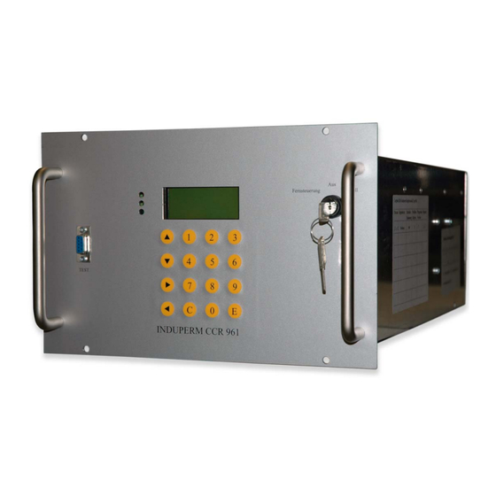
CCR961 MANUAL-GB 3.3 Operating Description Fernsteuerung Manuell TEST INDUPERM CCR 961 1. LED 2. Communication port 3. Arrow keys 4. LCD display 5. Key switch 6. The keys 0-9 + E & C 1. LED: RED (top) – YELLOW (in the middle) – GREEN (bottom) RED: A flashing red LED indicates that the regulator is in either ‘manual’... - Page 15 CCR961 MANUAL-GB If the green light is off for more than 1-5 seconds (adjustable), the step back-indication to the remote control will disappear. 2. On the communication port the oscilloscope or the PC can be connected to read out values from the regulator.
-
Page 16: The Menu's
CCR961 MANUAL-GB Press the E key to get into the adjusting mode. The key is moreover used for acknowledging. The 0 key is used to resetting any alarms. The key switch must be in the OFF position. The most frequent adjustments are described in the Step-by-Step instruction. 3.4 The menu’s There are more menu areas: Normal menu (no access code needed) with the menu’s N1 –... -
Page 17: Power Transformer
CCR961 MANUAL-GB 3.5 Power Transformer Standard sizes are as follows: 2,2 - 3 – 5 – 7,5 – 10 – 12,5 – 15 – 20 – 25 – 30 - 35kVA. The Transformers are, as standard, available for 230V or 400V. For all types larger than 20 kVA, the standard is 400V. -
Page 18: Ccr Installation
CCR961 MANUAL-GB 4 CCR installation 4.1 Unpacking the CCR shipment The CCR’s are supplied on a pallet, and covered in a plywood box. Remove the screws in the top and bottom of the plywood box, and the box can be lifted off the CCR pallet, and folded. - Page 19 CCR961 MANUAL-GB CCR front view Version B2:01-07-2015...
- Page 20 CCR961 MANUAL-GB Comments: Remote connection for RS485 can be by means of terminals or RJ45 plugs Input power cable dimension must be according to calculated max. input current Series circuit cables must be connected by means of cable shoes, and these are normally included in the delivery (mounted on lightning arrestors) Version B2:01-07-2015...
-
Page 21: Commissioning
CCR961 MANUAL-GB 5 Commissioning 5.1 Preparation Commissioning and adjustment normally have to be certified in a protocol. This protocol can be made by means of the serial interface on front of the CCR together with a Monitor Program, or it can be done by hand on, by reading values in the display. -
Page 22: Control Of Settings In Each Menu
CCR961 MANUAL-GB 5.2 Control of settings in each menu. 1. The CCR is entered into User Mode (from Normal menu 1), by pressing: >E< Enter Code for User Mode With > < (arrow right) the menus are controlled/corrected as follows: Menu Menu Default... - Page 23 CCR961 MANUAL-GB The CCR is entered into Factory Mode: >E< Enter code for Factory Mode With > < (arrow right) the menus are controlled/corrected as follows: Menu Menu Default Settings for circuits Settings Comments Name Value with Uout-max for other <...
-
Page 24: Step By Step Adjustments
CCR961 MANUAL-GB 5.3 Step by Step adjustments Operation and adjustments can be performed in different menus, please consult 961.002 for more details: Normal Menu (no code) with the menus N1 – N7: Normal CCR operation and data read-out User Menu (User code) with the menus U1 – U26: Standard user adjustments Factory Menu (Factory code) with the menus F1 –... - Page 25 CCR961 MANUAL-GB 3.1 Alarm acknowledge A current alarm can be a minimum (Imin) or a maximum (Imax) alarm, and each of these alarms will always switch-off the CCR. The CCR can only be switched-on again, when the actual alarm have been acknowledged. Other types of alarms, LAME or ISO, needs no acknowledgement as the CCR is not switched-off, and the alarms will automatically disappear when the alarm condition disappear.
- Page 26 CCR961 MANUAL-GB 3.4 Adjustment of number of intensity steps The Key switch is turned to position ”Manual” Press ”E” Enter the code for User Menu Press ”E” Press 11 times to the display shows ”Max no. of steps” ...
- Page 27 CCR961 MANUAL-GB Press 24 times to see ”Calibration of watch” in the display Press and the value for ”Hours” will start flashing Use the push-buttons 0 – 9 to enter the desired value for hour ...
- Page 28 CCR961 MANUAL-GB Press >E< 4 times until ” ^^^^” is shown in the display. Press -push buttons to choose the XXXX term Press >E< Press -push buttons to select the Z1 value Press >E< Press -push buttons to select the Z2 value ...
- Page 29 CCR961 MANUAL-GB ASCII Code: ( ASCII: opening parenthesis ) ASCII: closing parenthesis * ASCII: asterisk + ASCII: plus sign - ASCII: hyphen-minus . ASCII: period 0 ASCII: digit zero 1 ASCII: digit one 2 ASCII: digit two 3 ASCII: digit three 4...
- Page 30 CCR961 MANUAL-GB X ASCII: Latin Capital Letter X Y ASCII: Latin Capital Letter Y Z ASCII: Latin Capital Letter Z ` ASCII: spacing grave a ASCII: Latin Small Letter A b ASCII: Latin Small Letter B c ASCII: Latin Small Letter C d...
- Page 31 CCR961 MANUAL-GB See, that the display seems to be working normally (no flashing) The CCR module is switched-on in step 1, while observing the current in display. If the module seems to be working, the other steps are tested. ...
- Page 32 CCR961 MANUAL-GB Adjustments: Minimal procedure 1. The Key switch is set in position Manual 2. >E< 3. Enter code for user menu 4. >E< 5. Press >5< to start of learn procedure 6. Confirm ”All lamps OK?” by pressing >E< 7.
- Page 33 CCR961 MANUAL-GB Manuel correction in table with values for L / Ua. If the CCR is not able to perform a satisfying Learn procedure, or if you want to modify one or more values, the following procedure must be followed: Typical failures could be three horizontal lines in the display when a high percentage of lamps in a circuit are faulty, or the display of 1 faulty lamp, when you know that all lamps are Ok.
- Page 34 CCR961 MANUAL-GB I we increase the value 100 in table 0 for step 1, the limit for showing 1 faulty lamp will be increased. If the value is changed from 100 to 120, the limit for 1 faulty lamp will be changed from 176 to 186.
- Page 35 CCR961 MANUAL-GB 3.13 Control of transformer tapping Selection of the correct tapping on the output transformer can be based on a number of different criteria’s, such as expected variations on the mains supply etc. See the special document for more details.
- Page 36 CCR961 MANUAL-GB Version B2:01-07-2015...
-
Page 37: Remote Control
CCR961 MANUAL-GB 6 Remote Control 6.1 Standard RS485 The Mainboard includes all hardware and software for direct communication with a remote control system via RS485. The connection in the cubicle is as standard a set of terminals (-XX1) or a set of RJ45 connectors. Description of the RS485 communication protocol: General information: 19200 Baud, 8bit, no parity, 1 stop bit... - Page 38 CCR961 MANUAL-GB Byte 10-12: Iout analog decimal value 0 - 999 Byte 13-15: Lamp analog decimal value 0 - 999 Byte 16-18: Uout analog decimal value 0 - 999 Byte 19-21: ISO analog decimal value 0 - 999 Byte 22-23: CRC hexadecimal figure between 00 and FF Byte 24: Stop character *...
- Page 39 CCR961 MANUAL-GB Connections on terminals –XX1 for RS485 based remote control communication with the above described protocol. In the lower part of the picture is shown that, upon request, the terminals –XX1 can be exchanged to two nos. RJ45 connector houses, mounted on the board 961.745 Version B2:01-07-2015...
-
Page 40: Redundant Profibus
CCR961 MANUAL-GB 6.2 Redundant Profibus When a Profibus communication interface to the remote control system is required, the CCR Module will have a Redundant Profibus Board added internally, and this will then communicate with the CCR Main board in a RS485 protocol. The connections in the CCR cubicle is a set of terminals (-XX1). - Page 41 CCR961 MANUAL-GB FROM master IM184 Port Step bit 0 Step bit 1 Step bit 2 Status req. if = 1 cancel step info and set "tx status" Master bit positive edge trig !! Set time = 12.00 if = 1 set ccr time to 12.00 (noon) 0=tx status 1=tx analog analog pointer 0 (Iout=11H, Lamp=31H, Uout=51, E=71H)
- Page 42 CCR961 MANUAL-GB Explanations to the Profibus protocol. Port PA and PB is receiving the information from MASTER, while port PC and PD delivers the signals to MASTER. Bit PA-7, Status req. can be set to 1, to enable a request of tx status or tx analog without sending a step command at the same time.
- Page 43 CCR961 MANUAL-GB PD: 00100000 remote Step = 2 (Emin1 alarm, Emin2 alarm (Emin = ISO)) Profibus master will send flg. data bit to CCR: PA: 00000010 step 2 PB: 00000001 master, Status req. Profibus module will send flg. data bit to master: PC: 00000010 step 2 PD: 00100110...
- Page 44 CCR961 MANUAL-GB U-out: Step = 2 Profibus master will send flg. data bit to CCR: PA: 00000010 step 2 PB: 01010001 master, tx analog value type 2 ~ Uout Profibus module will send flg. data bit to master: PC: 00110000 48 ~ Uout = 0.48KV PD: 10100000 analog value type 2 ~ Uout...
-
Page 45: Parallel Control
CCR961 MANUAL-GB 6.3 Parallel control When a parallel interface is required, a separate parallel interface board is placed in the CCR cubicle, and this board will communicate with the CCR module via the RS485 serial bus. The latest parallel version is shown below: Version B2:01-07-2015... - Page 46 CCR961 MANUAL-GB The connections to the Parallel Interface board is done via the connectors J4, J5 and J6. These connectors are designed for max. 1mm2 flexible wire. If heavier wire is used we can offer a solution with 25 nos. terminals for 2,5mm2 cable. This row of terminals is mounted in the front of the CCR for easy access and is shown below.
-
Page 47: Ethernet Ip Addressable
CCR961 MANUAL-GB 6.4 Ethernet IP addressable The IP solution is similar to the solution for Parallel control, by mounting a special box in the CCR cubicle that will convert the IP communication to RS485 towards the CCR. The Protocol and set-up for this solution can be obtained in a separate document. Ethernet IP addressable Lan-com interface. -
Page 48: Dip-Switch Settings
CCR961 MANUAL-GB 6.5 Dip-switch settings There are dip switches on the Main Board and on the Profibus Board (only for Profibus solutions). The drawing below shows the setting of the dip-switches, both on the Main Board and on the Profibus Board. In solutions with a parallel remote control interface, the address on both Main Board and on the Parallel Board is normally set to 1. -
Page 49: Cut-Out Devices
CCR961 MANUAL-GB 7 Cut-Out devices 7.1 Standard FAA connector type The Cut-out device includes the following parts: - The Aluminum device with four nos. female FAA high Voltage connectors. Two of the plugs are connected to each end of the output transformer (S1 and S2 on terminals –XX4), and two are connected to ground. -
Page 50: Key Operated Safety Type
CCR961 MANUAL-GB 7.2 Key operated safety type When the key is turned the front of the Cut-out devise (with its high voltage connector) can be pulled out and turned 180° to change the function. THE CUT-OUT DEVICE MUST ONLY BE OPERATED WHEN THE CCR IS SWITCHED OFF! Version B2:01-07-2015... -
Page 51: Maintenance And Trouble Shooting
CCR961 MANUAL-GB 8 Maintenance and Trouble shooting 8.1 Regularly Control There is no direct demand for certain maintenance to be done on the CCR, but in the following is given a few recommendations, which could improve both MTBF, lifetime of the equipment as well as safety for maintenance personnel. -
Page 52: List Of Possible Failures
CCR961 MANUAL-GB 8.3 List of possible failures Failure Cause Correction Open circuit Repair circuit Many faulty lamps (open secondary sides Change lamps Imin on SIT) Cut-out device activated Set to normal position CCR module failure Change module Thyristor unit shorted Change module or Thyristor Imax Too much load change in series circuit... - Page 53 CCR961 MANUAL-GB List of spares Pos. Description 40A CCR Module 230/400V Profibus 961060 110A CCR Module 230/400V Profibus 961070 60A CCR Module 230/400V Profibus 961080 60A CCR Module 230/400V RS-485 961085 40A CCR Module 230/400V RS 485 961090 110A CCR Module 230/400V RS 485 961100 Additional coil for ISO box 961121 (Uout > 2KV) 961105 ISO box for 961, 42V (ISO-Interval) 961121 ISO box for 961,42V,Ver.2 (ISO-continuosly) 961124 Mainboard 961 V4:120707 961505 Profibus Board 961 961515 Memoryboard til 961 961535 Trigger Board 961 V4...
Need help?
Do you have a question about the CCR 961-SW4.00 and is the answer not in the manual?
Questions and answers