Table of Contents
Advertisement
Quick Links
Advertisement
Table of Contents

Summary of Contents for FLOW metrix Safsonic P
- Page 1 Safsonic P Handheld Ultrasonic Flow meter User Manual Safmag House P.O.Box 17143 Int Tel.: +27(0)312060630 498 Sydney Road Congella SA Tel.: 086 110 6028 Congella South Africa, 4013 enquiries@flowmetrix.co.za Durban Reg. No. CK 1986/11597/23 www.flowmetrix.co.za...
-
Page 2: Table Of Contents
CONTENT 1. Introduction ..........................1 1.1 Preface ....................... 1 1.2 Main Features ..................... 1 1.3 Principle of Measurement ..................2 1.4 Packing List (Standard Configuration) ..............2 1.5 Parts Identification....................3 1.6 Typical Applications ..................... 4 1.7 Data Integrity and Built-in Time-Keeper ............... 4 1.8 Product Identification-ESN .................. - Page 3 4. How To ............................23 4.1 How to judge if the instrument works properly ............ 23 4.2 How to judge the liquid flowing direction ............23 4.3 How to change between units systems .............. 24 4.4 How to select a required flow rate unit ............... 24 4.5 How to use the totalizer multiplier ..............
- Page 4 6.3 the Protocol....................... 34 6.4 Protocol Prefix Usage ..................36 7. Service ............................38 Appendix ............................40 1. Sound speed data of liquid (unit: m/s)..............40 2. Sound speed data of solid (unit: m/s)..............40 3. Sound speed in water at atmosphere pressure ............ 41...
-
Page 5: Introduction
1. Introduction 1.1 Preface Welcome to handheld ultrasonic flow meter that has been manufactured with patent technologies and is equipped with more functions and advanced performance than our previous versions. The ultrasonic flow meter has been upgraded based on the previous ultrasonic flow meter which is still the main product line of the company. -
Page 6: Principle Of Measurement
1.3 Principle of Measurement The ultrasonic flow meter is designed to measure the fluid velocity of liquid within a closed conduit. The transducers are a non-contacting, clamp-on type, which will provide benefits of non-fouling operation and easy installation. The transit time flow meter utilizes two transducers that function as both ultrasonic transmitters and receivers. -
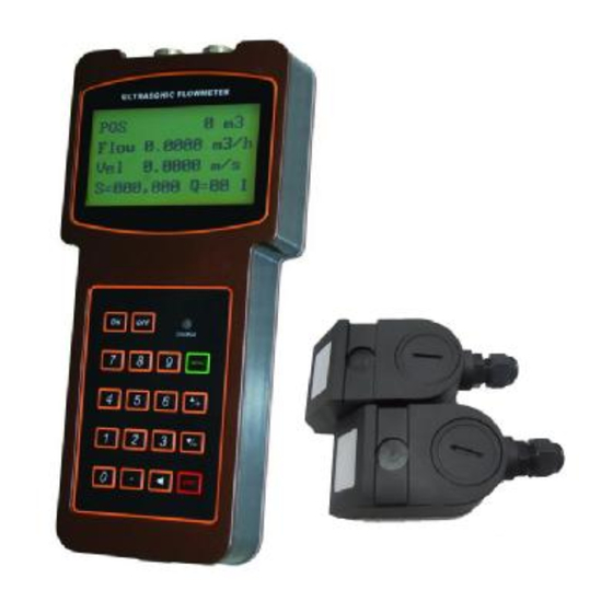
Page 7: Parts Identification
Name QTY (pcs) Main Unit Medium transducer Transducer cable 2*5m Data wire AC adapter Coupling grease Belt stretcher Tape Carrying case 1.5 Parts Identification Top View Bottom View ß---- AC/DC recharging adapter Instruction Manual... -
Page 8: Typical Applications
Transducer cable: RS232 interface cable 1.6 Typical Applications The ultrasonic flow meter can be virtually applied to a wide range of measurements. A variety of liquid applications can be accommodated: ultra-pure liquids, potable water, chemicals, raw sewage, reclaimed water, cooling water, river water, plant effluent, etc. Because the instrument and transducers are non-contacting and have no moving parts, the flow meter can not be affected by system pressure, fouling or wear. -
Page 9: Technical Specification
1.9 Technical Specification Linearity 0.5% Repeatability 0.2% Accuracy ±1% of reading at rates>0.2 mps Response Time 0-999 seconds, user-configurable Velocity ±32 m/s Pipe Size 20mm-6000mm Totalizer 7-digit totals for net, positive and negative flow respectively Liquid Types Virtually all liquids Setup values Modification Lockout. -
Page 10: Starting Measurement
2. Starting Measurement 2.1 Built-in Battery The ultrasonic flow meter can operate either from the built-in Ni-H rechargeable battery, which will last over 12 hours of continuous operation when fully recharged, or from an external AC/power supply from the battery charger. The battery charging circuits employ a scheme of constant-current and constant-voltage. -
Page 11: Keypad
parameters configured last time by the user or by the initial program. The flow measurement program always operates in the background of the user interface. This means the flow measurement will keep on running regardless of any user menu window browsing or viewing. Only when the user enters new pipe parameters will the flow meter change measurement to the new parameter changes. -
Page 12: Menu Windows
2.4 Menu Windows The user interface of this flow meter comprises about 100 different menu windows that are numbered by M00, M01, M02 … M99. There are 2 methods to enter certain menu window: (1) Direct going/entering. The user can press the MENU key followed by two-digit number keys. - Page 13 2.5 Steps to Configure the Parameters The following parameters need to be configured for a proper measurement: Pipe outer diameter Pipe wall thickness Pipe materials (for non-standard pipe materials*, the sound speed for the material must be configured too) *Standard pipe materials and standard liquids refer to those with the sound parameters that have already been programmed into software of the flow meter, therefore there is no need to configure them Liner material and its sound speed and thickness, if there is any liner.
-
Page 14: Transducers Mounting Allocation
The first-time users may need some time to get familiar with the operation. However, the user friendly interface of the instrument makes the operation quite easy and simple. Before long, the user will configure the instrument with very little key pressing, since the interface allows the user to go to the desired operation directly without any extra steps. - Page 15 Up s t r e a m Do wn s t r e a m Pi p i n g Co n f i g u r a t i o n Di me n s i o n Di me n s i o n a n d L u p L d n...
-
Page 16: Transducers Installation
2.7 Transducers Installation The transducers used by the series ultrasonic flow meter are made of piezoelectric crystals ceramic plate; both for transmitting and receiving ultrasonic signals through the wall of liquid piping system. The measurement is realized by measuring the traveling time difference of the ultrasonic signals. -
Page 17: V-Method Installation
2.7.2 V-method Installation V-method installation is the most widely mode for daily measurement with pipe inner diameters ranging from 15 mm to 400 mm. It is also called reflective mode. 2.7.3 Z-method Installation Z-method is commonly used when the pipe diameter is above 200mm. For insertion transducers, Z method is usually selected and used. -
Page 18: W-Method Installation
2.7.4 W-method Installation W-method is usually used on plastic pipes with a diameter from 15mm to 50mm. 2.7.5 N-method Installation N-method is used for small pipe size. But W-method has more often used than N-method. Thus, N-method is rarely used method in fact. 2.8 Installation Checkup Through the checkup of the installation, one can: check the receiving signal strength, the signal quality Q value, the traveling time difference of the signals, the estimated liquid... -
Page 19: Signal Strength
2.8.1 Signal Strength Signal strength indicates the amplitude of receiving ultrasonic signals by a 3-digit number. [000] means there is no signal detected and [999] refers to the maximum signal strength that can be received. Although the instrument works well if the signal strength ranges from 500 to 999, stronger signal strength should be pursued, because a stronger signal means a better result. -
Page 20: Time
2.8.4 Time Ratio between the Measured Total Transit Time and the Calculated Time This ratio would be used to check the transducer installation. If the pipe parameters are entered correctly and the transducers are installed properly, the value for this ratio should be in the range of 100±3. -
Page 21: Menu Window Details
3. Menu Window Details 3.1 Menu Windows Arrangement The ultrasonic flow meter supplies various of menus to meet user’s requests as below: M00~M09 windows for the display of the flow rate, velocity, date time, totalizers, battery voltage and estimated working hours for the battery. M10~M29 windows for entering the pipe parameter. - Page 22 Display NET totalizer, flow rate, velocity, signal strength, signal quality and working status Display date and time, flow rate, signal strength, signal quality and working status Display date and time, velocity, signal strength, signal quality and working status Display the wave shape of the receiving signal Dispay the battery terminal voltage and its estimated lasting time Display the all the detailed working status, signal strength, signal quality Display today’s total flow, velocity, signal strength, signal quality and...
- Page 23 Window for entering the fluid sonic velocity only for non-standard liquids Window for entering the viscosity of the non-standard liquids Window for selecting the proper transducers There are 14 different types of transducers for selection. If the user-type-transducers are used, 4 user type wedge parameters, which will be prompted by the software, should be entered following.
- Page 24 (2) Restore the instrument to the default parameters as the manufacturer did by pressing the dot key followed by the backspace key. Take care or make note on the parameters before doing the restoration Press-a-key-to-run or to stop totalizer for easier calibration Language selection option.
- Page 25 The users can employ the ESN for instrumentation management RS-232 setup. Baud rate can be 75 to 115200 bps M63-66 Not used for the ultrasonic flow meter. Input the frequency range for the frequency output. The biggest range is 0Hz-9999Hz. Default value is 1-1001 Hz Enter a flow rate value that corresponds to lower frequency Enter a flow Rate value that corresponds to higher frequency LCD display backlight control.
- Page 26 the transducer installation should be checked again. Displays total transit time and delta time(transit time difference) Displays the Reynolds number and the pipe factor used by the flow rate program. Not used for the ultrasonic flow meter. Not used for the ultrasonic flow meter. Command to record the pipe parameters entered by the user either to the built-in data logger or to RS-232C serial interface Command to record the diagnostic information either to the built-in data...
-
Page 27: How To
4. How To 4.1 How to judge if the instrument works properly Enter into M08, If ‘R’ is displayed on the screen, the instrument is working properly, If 'E' is displayed, the current loop output is over-ranged. Increasing the range setting in M57 will make the 'E' letter disappear. -
Page 28: How To Change Between Units Systems
4.3 How to change between units systems Use menu window M30 for the selection of unit system in English or Metric system. 4.4 How to select a required flow rate unit Use menu window M31 to select the flow unit first and then the timing unit. 4.5 How to use the totalizer multiplier Use window M33 to select a proper totalizer. -
Page 29: How To Use The Damper
instrument with default values except “instrument factor” and “network identification number” parameter 4.9 How to use the damper The damper acts as a filter for a stable reading. If ‘0’ is entered in window M40, that means there is no damping. A bigger number brings a more stable effect. But bigger damper numbers will prevent the instrument from acting quickly. -
Page 30: How To Use The System Locker
4.13 How to use the system locker The system locker provides a means of preventing inadvertent configuration changes or totalizer resets. When the system is locked, menu window browsing can be done without affecting any change, but any modifications are prohibited. The system can be locked without a password or with a 1 to 4 digit password. -
Page 31: How To Use The Frequency Output
4.15 How to use the Frequency Output There is a Frequency Output in all the series flow meters. This frequency output signal, which represents the flow rate, is intended to connect with other instruments. The Frequency Output is totally user-configurable. Generally, four parameters should be configured for the setups. - Page 32 4.17 How to produce an alarm signal There are 2 types of hardware alarm signals that are available with this instrument. One is the Buzzer, and the other is the OCT output. Both for the Buzzer and OCT output the triggering sources of the event include the following: There is no receiving signal There is poor signal received.
-
Page 33: How To Use The Built-In Buzzer
(5) Select item '6. Alarm #1' in M78 (6) Select item '6. Alarm #1' in M79. 4.18 How to use the built-in Buzzer The built-in buzzer is user-configurable. It can be used as an alarm. Use M77 for setups. 4.19 How to use the OCT output The OCT output is ON/OFF type. -
Page 34: How To Use The Working Timer
4.22 How to use the Working Timer Use the working timer to check the time that has passed with a certain kind of operation. For example, use it as a timer to show how long a fully-charged battery will last. Under M72, press ENT key and then select YES to reset the timer. -
Page 35: Troubleshooting
5.Troubleshooting 5.1 Power-on Error Displays and Counter-Measures The ultrasonic flow meter provides an automatic power-on diagnosis for the hardware problems. When any message (with the power on) in the following table displays, counter-measures should be taken. Error message Causes Counter-measures ROM Testing Error (1)Power on again Segment... -
Page 36: Other Problems And Solutions
(4)Pipe liners thick. (5)Transducer cords are not properly connected Hardware Error Hardware problem Contact the factory (1)Poor signal detected (2)Transducers installed (1)Relocate measuring improperly place (3)Too much fouling PoorSig Detected (2)Clean the spot (4)The pipe liners are too (3)Check the cords thick. - Page 37 (value) has a satisfactory value? The problems are likely caused by the user who has used the ‘Set Zero’ function on this non-standstill flowing pipe. To solve this problem, use the ‘Reset Zero’ function on menu window M43. The displayed flow rate is much lower or much higher than the actual flow rate in the pipe under normal working conditions.
-
Page 38: Communication Protocol
6. Communication Protocol 6. 1 General The ultrasonic flow meter integrates a standard RS-232 communication interface and a complete set of communication protocols that are compatible with that of the Fuji’s ultrasonic flow meter. 6.2 Interface Pin-out Definition for battery recharge, positive input not used OCT output not used... - Page 39 M@(CR)*** Send a key value as if a key is pressed LCD(CR) Return the current window display FOdddd(CR) Force the FO output with a frequency in dddd Hz ESN(CR) Return the ESN for the instrument Dddddddd(CR)(LF) RING(CR) Handshaking Request by a MODEM OK(CR) Response from a MODEM No action...
-
Page 40: Protocol Prefix Usage
6.4 Protocol Prefix Usage Prefix P The prefix P can be added before any command in the above table to have the returning data followed with two bytes of CRC check sum, which is the adding sum of the original character string. - Page 41 6.5 Codes for the Keypad The codes for the keypad should be used when the instrument is connected with other terminals that operate the instrument by transmitting the ‘M’ command along with the keypad code. By this function, remote operation of this instrument can be realized, even via the Internet.
-
Page 42: Service
7. Service 7.1 Warranty The products manufactured by Flowmetrix SA are warranted to be free from defects in materials and workmanship for a period of one year from the date of shipment to the original purchaser. Flowmetrix SA obligation should be limited to restoring the meter to normal operation or replacing the meter, at Flowmetrix SA choice, and shall be conditioned upon receiving written notice of any alleged defect within 10 days after its discovery. - Page 43 Take notice that the cost for repairing can only be determined after receipt and inspection of the instrument. A quotation will be sent to the customer before proceeding with the service. Important Notice for Product Return Before returning the instrument for warranty repair or service, please read the following carefully: 1.
-
Page 44: Appendix
Appendix 1. Sound speed data of liquid (unit: m/s) Liquids Sound speed Liquids Sound speed Water (20℃) 1482 Glycerin 1923 Water (50℃) 1543 Petrol 1250 Water (75℃) 1554 66# Petrol 1171 Water (100℃) 1543 80# Petrol 1139 Water (125℃) 1511 0# Diesel 1385 Water (150℃) -
Page 45: Sound Speed In Water At Atmosphere Pressure
3. Sound speed in water at atmosphere pressure Unit: t (Deg C) v (m/s) 1402.3 1496.6 1542.5 1555.1 1407.3 1499.2 1543.5 1555.0 1412.2 1501.8 1544.6 1554.9 1416.9 1504.3 1545.5 1554.8 1421.6 1506.7 1546.4 1554.6 1426.1 1509.0 1547.3 1554.4 1430.5 1511.3 1548.1 1554.2 1434.8...
Need help?
Do you have a question about the Safsonic P and is the answer not in the manual?
Questions and answers