
Related Manuals for Pentax EPK-i


Summary of Contents for Pentax EPK-i
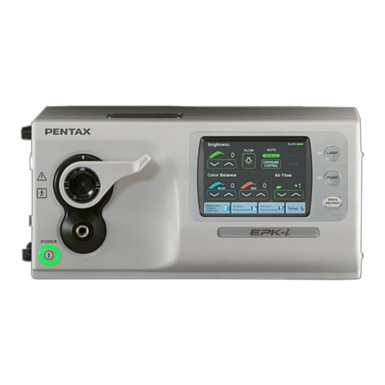
- Page 1 SERVICE MANUAL (Version 03) High-end Video Processor PENTAX EPK-i Medical Instrument Division / Service Technical Group MNL-045-03 / May 16, 2008...
-
Page 2: Table Of Contents
3) This Service Manual voids preceding "New Product Repair Guide" for the same model, if any. 4) Upon request, PENTAX will provide qualified service personnel with further information to service this product provided that the requested information needed within the range of... -
Page 3: Specifications
Automatic / Manual Brightness control Adjustable by +/- 5 steps each Auxiliary lamp 3W White LED (IEC60825-1) PENTAX Color Video Endoscope i-series and K-series Scope compatibility (K-series with Y/C output) Color correction Red and Blue each adjustable by +/- 5 steps each Adjustable automatically with “White Bal”... -
Page 4: General Explanations
1) High Definition image> High Definition images can be created with “Mega Scope 90i” which has a mega pixel CCD. The 90i scope provides the image data in digital signal to the EPK-i. The EPK-i can process the image signal without converting the analog signal. The EPK-i has a DVI (Digital Visual Interface) output port. -
Page 5: Functions
12) Processor ID>The processor model name “EPK-i” and its serial number have been stored as ID. These information must be necessary for the LAN environment. - Page 6 The 12 bit YCbCr signal is processed by enhancing or changing color with the front panel operation with the FPGA (U2). The processed YCbCr image signal is converted in to 10 bit RGB signal with the DSP (U2), and sent to the FPGA (U39).
- Page 7 4)-2 Rotary shutter control> To obtain a stiller frozen image, it is necessary to control an exposure time of light. It is accomplished by adjusting the hole on Rotary shutter (M4). The parts related to Rotary shutter consist of Rotary shutter (M4), Space motor (M6), Photo interrupter (PI1) and Shutter (M3). These are controlled with Peripheral Board (G700).
-
Page 8: Configuration (Main Parts)
Bypass Board (P700) Switching Power Supply (PS1) Igniter (IGN1) Lamp Power Supply (LU1) Lamp Interlock Switch (SW2) Mechanical Block Photo-1 EPK-i Main parts Rotary Shutter Iris Motor (M1) Main Motor (M4) Rotary Shutter Rotary Shutter Hole Control Motor (M6) Iris... -
Page 9: Electrical Safety Test
5. Precaution - Important 1) General You have to take utmost care to follow the general rules and practice for safety in servicing electrical medical equipment. 2) Power off before servicing For electrical safety, make sure to disconnect the power cable before opening the cover. 3) Route of electrical wire Be sure to keep the original routes of the electrical wires and the original positions of the cores. - Page 10 A way of replacing the lamp bulb and reusing the heat sink is described below. Important: 1) This job must be done by a person who has got the service training for the EPK-i. 2) The IR cut filter cannot be reused, must be replaced together with the lamp bulb. A spoiled filter may cause heat injury due to intensive light through the scope.
- Page 11 6) Reset the lamp life meter with the following procedures a) to i). a) Power on the EPK-i, press the “Menu” key of the exclusive keyboard to show the menu cabinet. Note: The menu cabinet will appear on the monitor that has been selected with “SD Monitor” or “HD Monitor” of “Keyboard Menu Output”...
- Page 12 ST-7022 Photo-4 Air flow & pressure meter 2) Turn on the EPK-i and wait until the system is ready. Then tap “Set up” button on the touch panel (Refer to Photo-5 Left). 3) Tap “Printer” button on the next screen (Refer to Photo-5 Middle).
- Page 13 5) Confirm if the touch panel has changed in the next screen as shown in Photo-6 Left. Page buttons Photo-6 Jig mode on touch screen 6) Enter key command “Ctrl+Alt+Contrast enhance” (with the ordinary keyboard, “Ctrl+Alt+F7”) to show “PASSWORD?” prompt on the CRT monitor (Refer to Photo-7). e x c a l i b u r Photo-7 Password operation 7) Answer “PASSWORD?”...
- Page 14 Photo-8 Processor Adjust Menu Photo-9 Pump Level Adjustment 11) Detach the air flow meter and attach the air pressure meter to the EPK-i (Refer to Photo-4). 12) Select “Level-1” and record the adjusted value and the measured air pressure value.
- Page 15 6.3 Iris 6.3.1 Iris replacement 1) The iris unit is located underneath Lamp Power Supply (LU1). Thus you need to remove Lamp Power Supply first with the following procedures: a) Remove Cove for power supply. b) Remove Lamp Power Supply (LU1). c) Remove Lamp Power Supply Tray by unscrewing the three screws.
- Page 16 RT14 RT13 TP52 TP31 TP53 TP32 Photo-14 Peripheral Board (G700) 6.4 Peripheral Board (G700) After Peripheral Board (G700) is replaced, the following adjustments are necessary. 6.4.1 Pump air flow adjustment Perform “6.2.2. Pump air flow adjustment”. 6.4.2 Iris adjustment Perform “6.3.2. Iris position adjustment”. - 14 -...
- Page 17 Caution: Pay attention to the connection between the extension card and Mother Board (E700), the extension card and Process Board (H700). 2) Connect a VGA monitor to the DVI port of the EPK-i. Note: 1)VGA monitor is necessary to be connected for the VGA port termination.
-
Page 18: Version
2) System file “33UH071-xx.rbf” (The adequate version file is provided by PENTAX. “xx” version number) <Procedures> 1) Connect the USB memory to the USB port and turn on the EPK-i and wait until the system is ready. Then tap “Set up” button on the touch panel (Refer to Photo-16 Left). - Page 19 11) After the Updating finishes, message “Complete” appears on the next screen (Photo-19 Right). Note: If the Updating has failed, message “Complete” will not appear. In this case tap “Quit” button and repeat the procedures from 6). 12) Turn OFF the EPK-i. Message “Complete” Tap ”Start” button Tap “Quit”...
-
Page 20: Dielectric Strength Test
Important: After opening the cover of the unit for repair, the electrical safety test is indispensable. 7.1 Dielectric strength test Caution: 1) Be sure to keep away from the equipment while the high voltage is being applied to the EPK-i. 2) This test is one kind of destructive tests. Multiple tests may damage the EPK-i. -
Page 21: Leakage Current Test
5) Turn off the EPK-i and change the polarity of the AC power by reversing the AC plug. Caution: Surely turn off the EPK-i before the polarity of the AC input is switched. Because the EPK-i has a protect function against momentary power down, the DC power supply unit may not work when the power has been turned off and on momentarily. -
Page 22: Trouble Shooting
8. Trouble shooting Symptom CHECK ACTION Check the fuses in the fuse box located above the AC inlet. If they have been brown, you need to find a part Fuse that may cause the excessive load by disconnecting Power does not turn parts one by one. -
Page 23: Wiring Diagram
9. Wiring Diagram CONTROL PANEL BACK PANEL BLOCK CARD CAGE BLOCK C501 CR10 B508 L700 I/O-1 Board C542 E700 CN38 RGB*2,Y/C*2,Video Mother Board Mark Tube Inverter F700 B510 DIMM Position CR24 H700 SBC Board B521 O700 Process Board CR14 B522 C545 COM1 Video...
Need help?
Do you have a question about the EPK-i and is the answer not in the manual?
Questions and answers