Table of Contents
Advertisement
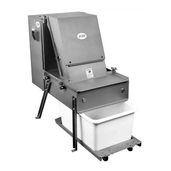
FROZEN MEAT CHIPPER
Operating Manual and Parts List
Applicable on Machines Starting with Serial No. 10200
Biro Designed
+
MODEL FBC-4800SS
STAINLESS STEEL
IMPORTANT NOTICE
This Manual contains important
safety instructions which must
be strictly followed when using
this equipment.
Biro Built
+
FBC-4800
029-5-07-17
029-10-05-16
PTCT
Advertisement
Table of Contents

Summary of Contents for BIRO FBC-4800SS
- Page 1 MODEL FBC-4800SS STAINLESS STEEL FROZEN MEAT CHIPPER Operating Manual and Parts List Applicable on Machines Starting with Serial No. 10200 Biro Designed Biro Built IMPORTANT NOTICE This Manual contains important safety instructions which must be strictly followed when using PTCT FBC-4800 this equipment.
-
Page 3: Table Of Contents
TABLE OF CONTENTS Page NOTICE TO OWNERS AND OPERATORS ......... 1 SAFETY TIPS . -
Page 5: Notice To Owners And Operators
Manual. Warnings related to your personal safety are indicated by: Warnings related to possible damage are indicated by: BIRO also has provided warning labels on the equipment. If any warning label or Manual be- comes misplaced, damaged, or illegible, please contact your nearest Distributor or BIRO directly for a replacement. -
Page 6: Safety Tips
This Machine BEFORE Cleaning or Servicing. · NEVER Leave Machine Unattended While Operating. · PROMPTLY REPLACE Any Worn or Illegible Warning Labels. · ALWAYS Read Operation and Service Manual BEFORE Operating, Cleaning, or Servicing. · USE ONLY BIRO Parts and Accessories Properly Installed. -
Page 7: Installation
UNCRATING AND SET UP 1. Read this Manual thoroughly before installation and operation. Do not proceed with installation and operation if you have any questions or do not understand anything in this Manual. Contact your local Distributor, or BIRO FIRST. - Page 8 No. 10 WIRE if the distance from the machine to electrical box is 25 feet or less. Over 25 feet a MINIMUM OF No. 8 WIRE is to be used. (9) The BIRO Manufacturing Company is not responsible for permanent wiring, connection or installation. NOTE TO OWNER AND ELECTRICIAN: IF THIS MACHINE IS NOT CORD...
-
Page 10: Operation
OPERATION MOVING SHUTTLE WITH SHARP CHIPPING BLADES TO AVOID SERIOUS PERSONAL INJURY · ONLY Properly Trained Personnel Should Use This Equipment. · ALWAYS Keep Hands Clear of Sharp Chipping Blades and Other Moving Parts. · NEVER Operate With Product Chute Cover in the Open Position. ·... -
Page 11: Trouble Shooting Machine Operation
B. TROUBLE SHOOTING MACHINE OPERATION 1. Machine is not chipping properly. Check the following items: A. Product block may be frozen too hard (temperature should be 15 to 25 degrees). B. Product block may be too soft. C. Either the Guillotine Knife (Item No. 51380) or the Runner Blades (Item No. 51379) may be dull or broken. D. -
Page 12: Maintenance
· NEVER Bypass, Alter, or Modify This Equipment in Any Way From Its Original Condition. · PROMPTLY REPLACE Any Worn or Illegible Labels. · USE ONLY GENUINE BIRO Parts and Accessories Properly Installed. LUBRICATION 1. SLIDE RODS: Lubricate daily or after each cleaning with a good grade food oil. -
Page 13: Cleaning
Electrical Components. · ALWAYS Thoroughly Clean Equipment at Least Daily. CLEANING THE BIRO FROZEN BLOCK CHIPPER: 1. Turn “OFF”, unplug machine from power source, and perform lockout/tagout procedures. 2. Lift Chute Cover until notch in Chute Cover Support is in line with bracket on the side of the chute. -
Page 14: Parts Diagrams
RECOMMENDED FLOOR ANCHOR SUPPLIED -16 ´ 1½² EXPANSION ANCHORS FOR EACH (2) FLOOR CHOCK, FIGURE No. 17... - Page 15 PARTS LIST For: SANITARY TIN MACHINES starting with Serial No. 3100 to Serial No. 5297 & For: STAINLESS STEEL MACHINES starting with Serial No. 10200 IMPORTANT: ALWAYS ADVISE SERIAL NUMBER WHEN ORDERING PARTS FIG. NO. ITEM NO. DESCRIPTION HHS129S Hex Head Screw, -13 ´...
- Page 17 PARTS LIST IMPORTANT: ALWAYS ADVISE SERIAL NUMBER WHEN ORDERING FIG. NO. ITEM NO. DESCRIPTION 51382 Slide Rod 51547 Front Bearing Bar Assembly w/Bearings 51503 Front Slide Bearings HHS135S Hex Bolt, -13" ´ 2 ", SS LW30S Lock Washer, ", SS 51340 Runner Blade Retainer FHS36S...
-
Page 18: Runner And Guillotine Blade Replacement
RUNNER BLADE AND GUILLOTINE BLADE REPLACEMENT PROCEDURE 1. Remove the slide assembly hex head mounting bolts (3 ea.) 2. Remove Item No. 51549 slide assembly from the machine. 3. Place on workbench. 4. Remove the runner support hex head bolts (4 ea.) 5. - Page 19 No. 51549 Slide Assembly Complete With Blades and Without Bearing Bars...
- Page 20 INSTALLATION INSTRUCTIONS ALTERNATE GROVE GEAR REDUCER REPLACING MORSE GEAR REDUCER · ALWAYS Turn Off, Unplug From Power Source and Perform Lockout/Tagout Procedures to the Machine Before Any Service is Performed. REMOVAL A. Remove Item No. 51575 Drive Cover Door. B. Remove four bolts holding the Item No. 50690 Pushbutton box to the Item No. 50757 Drive Cover and let box hang free.
- Page 21 INSTALLATION A. Put the four ½-13 ´ 1¾ bolts and lock washers in the mounting plate first. Attach the mounting plate to the Gear Reducer (Grove) using the four -14 ´ 1¾ bolts and lock washers. B. Mount the Gear Reducer and Mounting Plate combination to the machine frame and tighten the four ½-13 bolts.
- Page 22 LUBRICATION FOR GROVE GEAR REDUCER 1. Factory Filling The speed reducers are oil filled at the factory to the proper level for the standard mounting position. The oil level should be checked and adjusted (if necessary) prior to operation, using the oil level plug provided and while the unit is oriented in its operating position.
- Page 23 51074G GEAR REDUCER LUBRICATION AND MAINTENANCE LUBRICANTS FOR 51074G GEAR REDUCER WORM GEAR REDUCERS The precision-made gears and bearings in Grove Gear Speed Reducers require high-grade lubricants of the proper viscosity to maintain trouble-free performance. For best results, use lubricants on the following chart for worm gear reducers.
- Page 24 No. 51074G GROVE GEAR REDUCER PARTS DIAGRAM Item No. Description Item No. Description 51074G-1 Gear Housing 51074G-18 Output bearing (cup & cone) 51074G-19 Hex head cap screw 51074G-2 Pipe plug 51074G-20 Single output shaft 1 dia. 51074G-3 Vent plug 51074G-22 Gear spacer 51074G-5 Input cover...
-
Page 25: Morse Gear Reducer Diagram & Lubrication
MORSE GEAR REDUCER 51074 — 1 Housing 51074 — 8 Bearing Input 51074 — 15 Key Gear 51074 — 22 Cap Screw 51074 — 2 Motor Flange 51074 — 9 Bearing Input 51074 — 16 Key Output 51074 — 23 Lock Washer 51074 —... -
Page 26: Old And New Style Blades And Operator's Notes Operator's Notes
Due to replacement of old style slide assemblies with the new style slide assemblies on the early Model FBC-4800SS BIRO Frozen Block Chippers, it has become necessary that we ask you to order your runner blades and guillotine knives by Style/Item Number. -
Page 27: Operator's Signature Page
OPERATOR’S SIGNATURE PAGE WARNING READ AND UNDERSTAND THIS ENTIRE MANUAL BEFORE SIGNING BELOW MY SIGNATURE ATTESTS THAT I HAVE COMPLETELY READ AND UNDERSTAND THIS MANUAL. I REALIZE THAT THIS MACHINE, IF OPERATED CARELESSLY, CAN CAUSE SERIOUS INJURY TO MYSELF AND OTHERS. SUPERVISOR’S NAME (PRINT) SIGNATURE... -
Page 28: Limited Warranty
The warranty card must be returned to The Biro Manufacturing Company for proper registration. If no warranty card is returned to BIRO, the warranty period will begin from the date the machine was originally shipped from the factory.
Need help?
Do you have a question about the FBC-4800SS and is the answer not in the manual?
Questions and answers