Table of Contents
Advertisement
Advertisement
Table of Contents

Summary of Contents for Caswell CAD-0205
- Page 1 CAD-0205 Series Communication Appliance Users Manual Revision: 1.4 This certificate of conformity of CAD-0205 series with actual required safety standards in accordance with 89/366 ECC-EMC Directive and LVD 73/23 ECC This product meets all safety requirements per UL60950 standard.
-
Page 2: Table Of Contents
Hard drive Install ..................11 Thermal Pad Install ................11 Remove and Install DIMM ..............12 Remove and Install CF card ..............14 2.10 Use a Client Computer ................15 Chapter 3 BIOS Setting ................. 17 CAD-0205 Series User’s Manual... -
Page 3: Chapter 1 Introduction
Introduction About This Manual This manual contains all required information for setting up and using the CAD-0205 series. CAD-0205 provides the essential platform for delivering optimal performance and functionality in the entry communications appliance market segment. This manual should familiarize you with CAD-0205 operations and functions.CAD-0205-3421 series provide up to 4 on-board Ethernet... -
Page 4: Board Layout
Board Layout Figure 1-1 Board Layout of CAD-0205 M/B System Block Diagram Pineview-M Onboard VGA Pin header ICH8M CF Socket BIOS/Firmware 2xSATA PCI-E x1 slot Mini PCIe slot PCI-E PCI-E PCI-E PCI-E GbE-0 GbE-1 GbE-2 GbE-3 82583V 82583V 82583V 82583V... -
Page 5: Product Specification
A semi-cutting hole for wireless antenna 40W, 12V power adapter Dimension 182x150x40mm Storage temp.: -20°C to 75°C Environmental Operating temp.: 0°C to 35°C.Fanless requirements Humidity: 10 to 90% RH non-condensing CAD-0205 Series User’s Manual... -
Page 6: Chapter 2 Getting Started
Chapter 2 Getting Started This section describes how the hardware installation and system settings should be done. Included Hardware The following hardware is included in package: CAD-0205 Communication Appliance System Board One null serial port cable AC-DC Adapter ... -
Page 7: Hardware Configuration Setting
2.3.1 CAD-0205 System 2.3.2 CAD-0205 System Board Jumper In general, jumpers on CAD-0205 system board are used to select options for certain features. Some of the jumpers are configurable for system enhancement. The others are for testing purpose only and should not be altered. To select any option, cover the jumper cap over (Short) or remove (NC) it from the jumper pins according to the following instructions. -
Page 8: Location Of Jumpers
+5V & +12V Power Connector (Only Output) J10,J11 SATA connector USB connector J13~J16 RJ45 connector Console Port DC Power Jack CMOS Clear Header JP4,JP5 By-pass and normal mode SMB Header JP13 MCU Programming Header HDD LED +Power LED By-pass LED CAD-0205 Series User’s Manual... - Page 9 J5:KB+MS Header Definition Signal Name Signal Name Mouse DAT Keyboard DAT Mouse CLOCK Keyboard CLOCK J9:+5V & +12V Power Connector (Only Output) Signal Name VDD_12V VDD_5V JP1:CMOS Clear Function 1-2 Short Normal Operation 2-3 Short Clear CMOS Contents CAD-0205 Series User’s Manual...
-
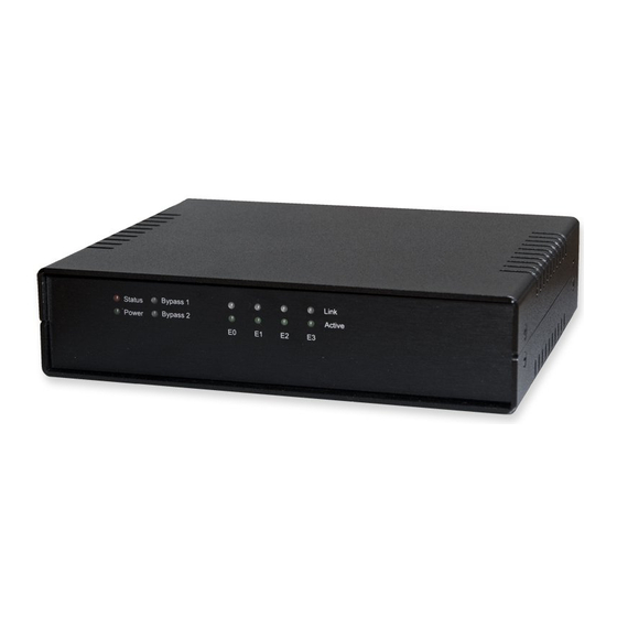
Page 10: The Chassis
The system is integrated in a 1U desktop chassis (Fig. 2-1, Fig. 2-2). On the front panel you will find a Power / HDD / Ethernet LED. Fig. 2-1 Front view of the chassis Fig. 2-2 Rear view of the chassis CAD-0205 Series User’s Manual... - Page 11 There are four cables connect from bottom cover to board connector. (FAN cable; GND cable SATA cable; SATA power cable) Please remove these cables first then remove bottom cover. Using a tweezers can help to pull out the cable CAD-0205 Series User’s Manual...
-
Page 12: Hard Drive Install
Hard drive Install The CAD-0205 system has supported SATA HDD function; please follow steps to install SATA HDD drive. 1. Use 4 screws to secure the drive into bottom cover 2. Use 1 screw to secure the GND cable into the hard drive 3. -
Page 13: Remove And Install Dimm
Please make sure the thermal pad is cover over the chip Remove and Install DIMM Follow these steps to upgrade RAM module: 1. Obliquity inserts the DIMM into the socket and depresses DIMM until the retaining clips back in place CAD-0205 Series User’s Manual... - Page 14 Follow these steps to remove a DIMM: 1. Pull the retaining clips of DIMM socket simultaneously to unlock the DIMM 2. Remove the DIMM from the socket CAD-0205 Series User’s Manual...
-
Page 15: Remove And Install Cf Card
Insert the Compact Flash Card (Fig. 2-3) into the CF interface (Fig. 2-4). Fig. 2-3 Compact Flash Card Fig. 2-4 Insert Compact Flash Card into the CF interface The completed installation of Compact Flash Card is shown as Fig. 2-4 Fig. 2-4 Completion of Compact Flash Card connection CAD-0205 Series User’s Manual... -
Page 16: Use A Client Computer
2.10 Use a Client Computer Connection Using Hyper Terminal To access CAD-0205 via the console, Hyper Terminal is one of many choices. Follow the steps below for the setup: Note: Terminal software may need to update for correct console output. - Page 17 Turn on the power of CAD-0205 system, after following screen was shown: This is the end of this section. If the terminal did not port correctly, please check the previous steps. CAD-0205 Series User’s Manual...
-
Page 18: Chapter 3 Bios Setting
BIOS setup utility hot keys can be used at any time during the setup navigation process. These keys include <F1>, <F10>, <Enter>, <ESC>, <Arrow> keys, and so on. Control Keys Function The Up and Down <Arrow> keys allow you to select a setup item or ↑↓Up /Down sub-screen. CAD-0205 Series User’s Manual... - Page 19 The Plus and Minus <Arrow> keys allow you to change the field value of a particular setup item. For example: Date and Time. Plus/ Minus The <Tab> key allows you to select setup fields. CAD-0205 Series User’s Manual...
- Page 20 Advanced BIOS Setup Select the Advanced tab from the setup screen to enter the Advanced BIOS Setup screen. You can select any of the items in the left frame of the screen, such as SuperIO CAD-0205 Series User’s Manual...
- Page 21 You can use this screen to select options for the Super I/O settings. Use the up and down <Arrow> keys to select an item. Use the <Plus> and <Minus> keys to change the value of the selected option. The settings are described on the following pages. The screen is shown below. CAD-0205 Series User’s Manual...
- Page 22 Select the serial port you want to use for console redirection. You can set the value for this option to either COM1 or COM2. Serial Port Mode Select the baud rate you want the serial port to use for console redirection. USB Configuration CAD-0205 Series User’s Manual...
- Page 23 You can use this screen to select options for the CPU Configuration. Use the up and down <Arrow> keys to select an item. Use the <Plus> and <Minus> keys to change the value of the selected option. CAD-0205 Series User’s Manual...
- Page 24 From the Bypass Function Setting screen, press <Enter> to use the up and down <Arrow> keys to options normal or non_normal mode. This feature requires use with a jumper to switch non_normal_bypass or non_normal_open mode, please refer the page.8 <Location of Jumpers> The screen is shown below. CAD-0205 Series User’s Manual...
- Page 25 OEM logo. The Optimal and Fail-Safe default setting is Enabled. Add-On ROM Display Mode Set this option to display add-on ROM (read-only memory) messages. The Optimal and Fail-Safe default setting is Force BIOS. An example of this is a SCSI BIOS or VGA CAD-0205 Series User’s Manual...
- Page 26 Select the Exit tab from the setup screen to enter the Exit BIOS Setup screen. You can display an Exit BIOS Setup option by highlighting it using the <Arrow> keys. All Exit BIOS Setup options are described in this section. The Exit BIOS Setup screen is shown below. CAD-0205 Series User’s Manual...
- Page 27 The Fail-Safe settings are designed for maximum system stability, but not maximum performance. Select the Fail-Safe Setup options if your computer is experiencing system configuration problems. Select Load Fail-Safe Defaults from the Exit menu and press <Enter>. CAD-0205 Series User’s Manual...
Need help?
Do you have a question about the CAD-0205 and is the answer not in the manual?
Questions and answers