Table of Contents
Advertisement
Quick Links
Advertisement
Chapters
Table of Contents

Summary of Contents for Medonic M16C-US
- Page 1 Medonic M-series...
-
Page 2: Table Of Contents
Contents ..............................3 REFACE Introduction ........................... 3 1: S ...................... 5 ECTION AFETY NSTRUCTIONS Section Overview ........................... 5 1.1 Intended Use ..........................5 1.2 Safety Instruction ........................6 1.3 Biohazards ..........................6 1.4 Emergency Procedure ......................7 1.5 Warning Signs in Manual ....................... 7 1.6 Signs on Equipment ......................... - Page 3 7: C ........................59 ECTION ALIBRATION Section Overview ......................... 59 7.1 Preparations before calibration ................... 59 7.2 Calibration ..........................60 8: C & T ..............64 ECTION LEANING AINTENANCE RANSPORT Section Overview ......................... 64 8.1 Daily Cleaning ........................64 8.2 Monthly Cleaning ........................65 8.3 Six (6) Month Cleaning ......................
-
Page 4: P Reface
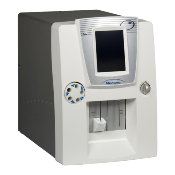
Preface Introduction Instrument Medonic M-Series 3-part hematology analyzer produced by Boule Medical for description human application. Serial number Serial number is located on the rear of the instrument. Figure 1.1 Figure 1.1 Figure 1.2 Software version The software version is displayed when starting up the instrument... - Page 5 User Definable Settings Operator requirements The following operator requirements must be fulfilled before operating the Medonic M-Series hematology system. Basic skills in a laboratory environment. Basic skills in hematology. Awareness of IVD (EU)/FDA (US) requirements regarding laboratory equipment.
-
Page 6: S Ection 1: S Afety I Nstructions
Warning Signs in Manual Signs on Equipment 1.1 Intended Use Description The Medonic M-Series is a fully automatic hematology analyzer intended for in vitro diagnostic testing of human blood samples under laboratory conditions. Operator Operator must have basic laboratory skills and be aware of good laboratory Requirements practice. -
Page 7: Safety Instruction
1.2 Safety Instruction Boule incorporates safety features within the instrument in order to protect the Description operator from injury, the instrument from damage and the test results from inaccuracies. Restrictions In order to insure the safety of the operator and instrument follow the instruction below: ... -
Page 8: Emergency Procedure
Handle any exposure according to established laboratory protocol biohazardous material regulations. The instructions for analyzer decontamination and disposal can be found on the Medonic home page, www.medonic.se under support. 1.4 Emergency Procedure In case of If there are any obvious signs of malfunction such as smoke or liquid leaking... -
Page 9: Signs On Equipment
1.6 Signs on Equipment Signs placed on the instrument define areas that need special attention or areas Description that contain danger. See IVD Symbol Table on page 9. Signs on equipment Figure 1.3 Figure 1.4 Figure 1.5 Figure 1.6... - Page 10 Batch code Serial number Catalogue number Manufacturer Authorised* Fragile, handle with Representative in the Biological Risks Use by care European Community In vitro diagnostic Lower limit of Upper limit of Temperature medical device temperature temperature limitation CONTROL L 16 CONTROL N 16 Consult instructions Low control, 16 Normal control, 16...
-
Page 11: S Ection 2: I Nstallation
Section 2: Installation Section Overview Introduction This section describes how to unpack and install the Medonic M-Series instrument. Contents This section contains the following topics: Topic See Page Unpacking / Operating Placement and Environment Installation Checklist and Menu Analyzer Cable, Interface, and Printer Connections... -
Page 12: Unpacking / Operating Placement And Environment
2.1 Unpacking / Operating Placement & Environment (continued) The following procedures must be followed exactly. Boule has no responsibility in case of faulty or erroneous installation. Important Installation/ The instrument should be placed in a laboratory environment according to the Operating guidelines below: ... -
Page 13: Installation Checklist And Menu
2.2 Installation Checklist and Menu Description Follow the quick Installation Checklist and Installation Menu step by step for best installation results. For more detail on each step refer to Sections 2.3 – 2.6. Installation Checklist Complete Unpacking / Operating Placement and Environment instructions in Section 2.1. Connect the power adapter to the back of the analyzer, but do not plug it into an electrical socket. - Page 14 2.2 Installation Checklist and Menu (continued) Step Action Press Step 2 [ENTER REAGENT BARCODES]. Press and hold Scan barcode 1 and then barcode 2 on the Diluent container. ( the ACTIVE or ON button each time a barcode is scanned.) o If using a Combination pack, following instruction for scanning in Diluent container.
-
Page 15: Analyzer Cable, Interface, And Printer Connections
2.3 Analyzer Cable, Interface, and Printer Connections Description All connections are located on the rear panel of the instrument. The connections available are as stated below: Figure 2.8 Number Part Function USB host ports Connects analyzer to USB devices. Electronic Sensors Connects Reagent level sensors to analyzer. -
Page 16: Reagent Installation
Supported Hemolyzing reagent and Isotonic Diluent, hereafter referred to as Lyse and Reagents Diluent. (Specifically designed by Boule for the Medonic M-Series system.) This section describes placement of reagent containers. Location of It is recommended that both the Diluent and the Lyse reagents are placed at Reagent the instrument level or below. - Page 17 2.4 Reagent Installation (continued) Step Insert The reagent level sensors into the corresponding reagent containers. Figure 2.10 Waste Connect the waste tubing to the analyzer. Place the other end of the waste tubing directly into the drainage system or into a waste container, following local regulations.
- Page 18 2.4 Reagent Installation (continued) Step Action Select MENU tab. Press [REAGENT SETUP] and then press [ENTER NEW REAGENTS]. Scan in barcodes on reagent containers, when all barcodes are entered a screen will display that reagent barcodes have been accepted. Figure 2.11 Figure 2.12 Return to MAIN Menu and press [ADVANCED].
-
Page 19: Changing Reagents
2.5 Changing Reagents Description The interlocked reagent system displays indicator and warning messages to alert the operator when reagents are running low and need to be changed. When this occurs perform the following: Step Action Select [MENU] to access the Main menu and then select [REAGENT SETUP]. Select [ENTER NEW REAGENT]. -
Page 20: Power Supply
2.6 Power Supply Electrical shock hazard. Installation of external electrical equipment such as CVT must only be carried out by authorized service engineers. Violating this might result in Warning injuries and/or loss of life and/or erroneous parameter results. In case of Symptom Solution High transient... -
Page 21: S Ection 3: G Eneral O Verview
Section 3: General Overview Section Overview Introduction This section contains general information about the instrument and optional accessories. Contents This section contains the following topics: Topic See Page General Instrument Overview System Menu System Flow Sample Volume, Throughput, and Parameters 3.1 General Instrument Overview Instrument Overview... -
Page 22: Menu Structure
3.2 Menu Structure Flowchart 3.1 Main Menu Structure Select Analysis Profile New Sample 11 possibilities of Analysis profiles ID_______ ¤ Next Main Menu ¤ 1,2,3..CE.. ¤ Prev Set Profile > New Sample > < ¤ Next Profile Sampling Device > (optional) ¤... - Page 23 3.2 Menu Structure (continued) Flowchart 3.2 Advanced Menu Structure Calibration Whole Blood > Predilute > Capillary Device > Closed Tube Device > Calibration Log > Exit < Maintenance Prime System ¤ Clean Orifice ¤ Fill System ¤ Cleaning Menu > Empty System ¤...
-
Page 24: System Flow
3.3 System Flow This section contains the system flow concerning standby and cleaning cycles. Description Flowchart 3.3 System Flow After 15 minutes* Screen Saver Mode** After 2 hours* Before 2 hours* In Standby Press anywhere on Mode screen to view screen Press anywhere on screen to view screen Press [EXIT]... -
Page 25: Sample Volume, Throughput, And Parameters
3.4 Sample Volume, Throughput, and Parameters Description The Medonic M-Series is a fully automated cell counter reporting up to 16 parameters. Autoloader: ≤ 300 µl Sample volume Cap Piercer: ≤ 250 µl MPA: ≤ 20 µl Open Tube: ≤ 110 µl ... -
Page 26: S Ection 4: I Nstrument S Etup
Section 4: Instrument Setup Section Overview Introduction This section covers the initial configuration needed to customize the instrument settings. Contents This section contains the following topics: Topic See Page Menu Selection Initial Setup Advanced Setup Reagent Setup User Interface 4.1 Menu Selection ... -
Page 27: Initial Setup
4.2 Initial Setup Initial setup of the instrument, except date and time, has been factory set to Initial Setup default values for the average Boule users. However, other user definable formats may be preferred, details are provided below. Setting up The date/time function is shown on all samples and printouts and should date/time always be setup correctly. -
Page 28: Advanced Setup
4.2 Initial Setup (continued) Setting up Change of display language is performed by following the instructions below: language Step Action Start by pressing [ADVANCED] from the MENU tab. Press [SETUP]. Press [SETUP MENU 2]. Press [REGIONAL SETUP], a list of local settings will be displayed. Press [MORE] until language button is displayed. - Page 29 4.3 Advanced Setup (continued) Follow the instruction below for interfacing analyzer to different printer types. Select Printer Type To connect printer see Section 2.3) Step Action Start by pressing [ADVANCED] from the MENU tab. Press [SETUP] and then [PRINT SETUP] to enter the Print Setup menu. Press [MORE] to view Printer type.
- Page 30 4.3 Advanced Setup (continued) Select Serial port sets the output port for sample data, select from the following: 2 = USB device port, 3 = USB memory stick, or 4 = USB RS232 serial port adapter Select USB vendor and product ID sets the USB identity for the analyzer. ...
- Page 31 4.3 Advanced Setup (continued) Keyboard Setup To setup the keyboard follow manufacturer instruction for setup and plug (optional) into analyzer keyboard port. See Section 2.3 for details. Step Action Start by pressing [ADVANCED] from the MENU tab. Press [SETUP], then [SETUP MENU 2]. Press [REGIONAL SETUP], and then [MORE].
-
Page 32: Reagent Setup
This section describes the functions of the reagent setup menu and how to access reagent statistics. Reagent Input The Medonic M-Series System is interlocked with specified Boule reagents for (Enter New optimal performance. The reagent containers must be identified by the Reagents) instrument before analysis of samples can begin. - Page 33 4.4 Reagent Setup (continued) Reagent statistics can be viewed in two ways: View Reagent Step Action Start by pressing [REAGENT SETUP] from the MENU tab. On the lower left-hand side of the Reagent Setup Menu, both the remaining cycles for Diluent and Lyse are displayed. (It is important to remember that cycles include analyses, wash cycles, background counts, primes, exit standbys, etc.) Figure 4.10...
-
Page 34: User Interface
4.5 User Interface Description This section describes the functions of available menus in the instrument that have not been described in any other section of this manual. Analysis Profile It shall be possible for authorized operators to customize analysis profiles. See following menu options: Step Action... - Page 35 4.5 User Interface (continued) To change background mode setting of the profile press [MISC. SETUP], choose [BACKGROUND MODE PROFILE] button, choose [X] or [ ] to activate or deactivate, and then [OK] to save. By enabling this setting, the current profile will behave like the factory default BACKGROUND profile (i.e.
- Page 36 > Product Brands > Medonic > Support > Downloads > Public > Documents. 1. Cheng C, Chan J, Cembrowski G, van Assendelft O. Complete Blood Count Reference Normal Range Interval Diagrams Derived from NHANES III: Stratification by Age, Sex, and Race...
-
Page 37: S Ection 5: S Ample A Nalysis
Section 5: Sample Analysis Section Overview Introduction This section covers the sample analysis routine, including how to analyze a sample in the five different modes offered in the Medonic M-Series. This section contains the following topics: Contents Topic See Page... -
Page 38: Startup Sequence
5.1 Preparations before Analysis (continued) The sample in the micropipette can be analyzed directly after collection and Handling of capillary blood for optimal results not longer than 10 minutes from collection. samples For capillary samples collected in Microtainer tubes follow the “Handling of venous blood samples”... - Page 39 5.2 Startup Sequence (continued) Step Action When complete the background count results are displayed. If the results are acceptable (see table for accepted background values according to section 5.3) , scan in the barcode on control vial and follow directions on the display to begin the second step of the startup sequence.
-
Page 40: Background Count
5.3 Background Count Background The following sequence is performed to check that the background count is low Check enough to run a sample. It is recommended to run a background check at the beginning of each shift. Step Action From the main screen press [NEW SAMPLE]. Press [NEXT PROFILE] or [PREV PROFILE] to scroll to Background. -
Page 41: Analyzing The Sample (Open Tube)
5.4 Sample Identification (continued) Step Action From the main screen press [NEW SAMPLE] or begin sample aspiration, which automatically opens NEW SAMPLE menu. Press numerical keys to enter sample ID or scan in the ID barcode from the sample tube. Press sample ID2 if a second ID is needed. Press [NEXT PROFILE] or [PREV PROFILE] to scroll to desired profile. - Page 42 5.5 Analyzing the Sample (Open Tube) (continued) Step Action Choose List, Sample, or Main menu to begin sample analysis. Analyzer must be in one of these operation modes to aspirate. Aspirate the sample through the aspiration probe by gently inserting aspiration probe into the sample tube, and then press the whole blood start plate behind the left aspiration probe.
-
Page 43: Analyzing The Sample (Pre-Dilution Procedure)
5.5 Analyzing the Sample (Open Tube) (continued) The instrument now switches to the sample analysis screen. Figure 5.13 Figure 5.14 In first screen displayed above Sample ID and profile can still be added. Approximately 30 seconds after aspiration the display switches to that in Figure 5.14 and no further ID entry is possible. - Page 44 5.6 Analyzing the Sample (Pre-dilute procedure) (continued) Time limitations Pre-dilute procedures are generally less precise than open and closed tube procedures and results may vary depending on local laboratory procedures and conditions. Blood cells may shrink and/or swell during the time between mixing in the beaker and the actual analysis, resulting in compromised values of MCV, MPV and the distribution between lymphocytes/mid-cells/ granulocytes (with indirect effect on calculated parameters, e.g.
-
Page 45: Analyzing The Sample (Micro Pipette Adapter, Mpa)
5.6 Analyzing the Sample (Pre-dilute procedure) (continued) Pre-dilute Start by selecting pre-diluted sample beaker and follow the procedure below: procedure Step Action Choose List, Sample, or Main menu to begin sample analysis. Analyzer must be in one of these operation modes to aspirate. Aspirate the pre-diluted sample through the pre-dilute aspiration probe by pressing and holding the pre-dilute start plate behind the right-side aspiration probe until aspiration starts. - Page 46 5.7 Analyzing the Sample (Micro Pipette Adapter, MPA) (continued) Collection Samples can be analyzed using the MPA from both venous and capillary blood methodology specimens. For venous collection, see Section 5.1 and steps at the end of this section for details of sample handling and preparation.
- Page 47 5.7 Analyzing the Sample (Micro Pipette Adapter, MPA) (continued) Step Action Always use gloves when in contact with potentially biohazardous materials. After puncture, wipe away the first drop of blood with a clean tissue or gauze pad. (First drop of blood often contains excess tissue fluid.) Warning When second drop forms, aspirate the sample as shown below, being careful to only allow the tip of the micropipette to touch the drop of blood (not the...
-
Page 48: Analyzing The Sample (Cap Piercing Device)
5.7 Analyzing the Sample (Micro Pipette Adapter, MPA) (continued) Venous collection sample preparation Step Action Follow sample preparation in Section 5.1. Use the micropipette holder to grasp a micropipette. (Holding the micropipette towards one end or the other, instead of in the middle, is best for filling and insertion.) Tilt sample vial at a 45 degree angle until blood is near the lip of the vial, but does not overflow. -
Page 49: Analyzing The Sample (Autoloader)
5.8 Analyzing the Sample (Cap Piercing Device) (continued) Step Action Figure 5.22 Figure 5.23 Always use gloves when in contact with potentially biohazardous materials. Caution should be applied when handling the cap piercer. Handling and operation by unauthorized personnel may result in injury. ... - Page 50 5.9 Analyzing the Sample (Autoloader) (continued) Step Action Menu Figure 5.24 Samples can also be analyzed without identification, but then only the sequence numbers will be present on the worklist. Selecting To select a different profile type for a sample press [SET PROFILE TYPE] in Profile Type Sampling Device ID Input display, select desired profile, and then press [OK].
- Page 51 5.9 Analyzing the Sample (Autoloader) (continued) Emergency Emergency (STAT) samples can be analyzed after the Sampling Device has Sample Analysis been started or during Sampling Device ID entry. There are several ways to analyze an emergency sample. Step Action Emergency sample can be analyzed through OT, pre-dilute, or MPA mode. ...
- Page 52 5.9 Analyzing the Sample (Autoloader) (continued) Follow the procedure below to operate the Sampling Device. Starting Sampling Device Step Action Unlock the center piece by turning it counterclockwise and lightly pulling it away from analyzer. Load the vacuum tube samples by placing the capped end towards outer edge of sample wheel and fitting it into designated slot.
-
Page 53: Results
5.10 Results This section describes the information that can be obtained from the sample Description analysis results. After sample After a sample has been analyzed the result information can be viewed in the analyze following three screen displays: Sample View 1 WBC histogram Total WBC count and differential values... - Page 54 5.10 Results (continued) Sample View 3 Normal Range display Sample results with sample results. Green bar = Results within Range Information Indicator – When highlighted user can press button to display system information messages. Red bar = Results Out-of-Range Press to print current sample analysis.
-
Page 55: Section Overview
Section 6: Quality Control (QC) and Blood Control Memory Section Overview Introduction The Medonic M-Series is equipped with a QC memory capable of displaying and printing Xb and Levey Jennings plots. Contents This section contains the following topics: Topic See Page... - Page 56 Using installed barcode reader, scan the Control ID from the blood control vial label or manually enter in barcode. Aspirate the blood control and wait for the results. The Medonic M-Series will identify this ID and match the results with the previously defined control assay values.
-
Page 57: Levey-Jennings Plots
6.1 Quality Control (QC) (continued) Press the [SAMPLE] or [LIST] buttons to display the selected samples. Once samples are displayed they can also be printed out in a Monthly QC summary report. After the control lot (profile) has been selected the Monthly QC button will become active. - Page 58 6.2 Levey-Jennings Plots (continued) Displaying and To display and print the L-J plots, follow the instructions below: printing L-J Plots Step Action Enter the QC menu and press [VIEW CON/CAL]. Scan the barcode label on the blood control tube, with the barcode reader, select control from Select Con/Cal Sample Menu, or manually enter in value.
-
Page 59: Initialization And Use Of Xb Function
6.3 Initialization and Use of Xb Function Description The Xb function in the Medonic M-Series follows strictly the Bull algorithm for the parameters MCV, MCH and MCHC. These parameters should not drift as a function of time within a large patient population. The recommended range setting is ±... -
Page 60: S Ection 7: C Alibration
See Page Preparations before calibration Calibration 7.1 Preparations before calibration It is recommended that the performance of the Medonic M-Series system is Before Calibration checked daily with certified controls authorized by Boule. Analyze control blood once in the open tube mode and compare results with the assigned values prior to calibration. -
Page 61: Calibration
7.2 Calibration Input Calibrator Follow the instruction in Section 6.1 Quality Control to access the QC menu Assay Values and to input Control/Calibrator Assay Values from the Assay sheet. Whole Blood The following instructions calibrate Open Tube, Cap Piercer, and Sampling Calibration Device modes. - Page 62 7.2 Calibration (continued) Scroll through parameter screens by using the [NEXT] button and verify that the CVs for the following parameters are within the stated limits: Parameter OT/CT CV% MPA/PD CV% < 2.2 < 3.2 < 1.8 < 1.8 < 5.8 <...
- Page 63 7.2 Calibration (continued) Authorized operator can update or change calibration factor by inputting the Authorization Code [2576]. Figure 7.3 Perform steps 9-12 for RBC, MCV, PLT, HGB, WBC, and MPV parameters. To move to the next parameter press [NEXT]. It is recommended to not change preset calibration factors for RDW%. If necessary, please contact local distributor or Boule service technician for procedure.
- Page 64 7.2 Calibration (continued) To calibrate pre-dilute follow Steps 1-17 above except select Pre-dilute Calibration [CALIBRATION] and then choose [PREDILUTE] instead of Whole Blood calibration in Step 6 and use pre-dilute mode for analysis. (See Section 5.6 for details on pre-dilute sample analysis.) Closed tube Device The closed tube device is calibrated with the calibration of the Open Tube Calibration...
-
Page 65: S Ection 8: C Leaning , M Aintenance & T Ransport
Section 8: Cleaning, Maintenance & Transport Section Overview Introduction This section contains information that is crucial for maintaining, transporting and storing the Medonic M-Series. Contents This section contains the following topics. Topic See Page Daily Cleaning Monthly Cleaning Six (6) Month Cleaning Re-location of instrument (within the laboratory) Short Term Shutdown (<12h) -
Page 66: Monthly Cleaning
8.2 Monthly Cleaning This section describes the cleaning procedure to be used to secure the correct Description function of the instrument on a monthly basis. Cleaning The Monthly Cleaning procedure takes approximately 10 minutes, instructions procedure are as follows: Step Action Clean the aspiration probes using an alcohol wipe. -
Page 67: Six (6) Month Cleaning
8.3 Six (6) Month Cleaning To increase the life of internal tubing in the instrument, the following cleaning Description procedure is strongly recommended. Press [ADVANCED] from Main menu, then press [MAINTENANCE], and Cleaning Procedure then press [CLEANING MENU] to enter the Cleaning Menu. ... -
Page 68: Re-Location Of Instrument (Within The Laboratory)
Power on unit. Perform Prime. Verify Background. It is recommended that the performance of the Medonic M-series system is checked with certified blood controls authorized by Boule. 8.5 Short Term Shutdown (<12h) This section describes the procedure when transporting or shutting down the Description instrument for a shorter period of time (<... - Page 69 8.5 Short Term Shutdown (<12h) (continued) The instrument should be transported in temperature conditions between 5 Guidelines for transport to 32 ºC (41 to 90 ºF) Humidity should be less than 80%. > 8.6 Re-packaging and Long Term Shutdown ( 12h) Description This section describes the procedure when transporting or shutting down the...
-
Page 70: Permanent Shut-Down And Storage
WEEE symbol (as given in the margin) and there is a procedure to allow waste collection and recycling of the equipment at the end of it’s life cycle. The instructions for decontamination can be found on the Medonic home page www.medonic.se under User Support. -
Page 71: S Ection 9: P Arameter And S Ystem I Nformation M Essages
Section 9: Parameter and System Information Messages Section Overview Introduction The Medonic M-Series has several parameter and system information messages related to the measured parameters and the instrument. These messages alert the operator of possible pathologic samples and parameter value and instrument errors. -
Page 72: System Information Messages
Note: If various HF, HH, HL, or HN Indicators repeatedly appear check High Altitude Compensation, mode may need to be changed to Moderate or Maximum compensation in higher elevations. A more detailed description can also be found in the User Definable Settings document, which can be located at www.medonic.se > Support > Downloads > Public > Documents. - Page 73 Out-of-linear range indicators (WBC, HGB, RBC, PLT) The sample can be diluted and rerun, and then the AL – Result is above The result is above linear range. dilution factor can be linearity multiplied with the result to calculate the correct value. BL –...
-
Page 74: Parameter Limitations Of Automated Blood Cell Counters
Air bubbles – run prime The time for the liquid meniscus to pass from the cycle lower to the upper detector is unreasonably short. Air bubbles – run prime Air bubbles were detected by the start detector in cycle the measuring tubes. Run a “Prime cycle”, before Possible orifice blockage: The liquid meniscus in the measuring tube never... - Page 75 9.3 Parameter Limitations (continued) MCV / HCT Limitations As HCT is the product of MCV x RBC, any erroneous result in MCV and/or RBC will produce an equal error in the HCT parameter. Limitation Description Red Blood Cell Agglutination of RBC may produce an erroneous MCV value and therefore a false HCT. Agglutination An excessive number of WBCs might cause interference within the RBC population and therefore a false MCV value.
- Page 76 9.3 Parameter Limitations (continued) RBC Limitations The red blood cell dilution contains all the cellular elements of the blood: RBC, WBC, and PLT. Platelets are not counted since the size falls below the discriminator threshold. Leukocytes are included in the RBC count, but since the ratio of RBCs to WBCs is approximately 1000:1, the introduced WBC count is almost negligible.
- Page 77 Chemotherapy Cytotoxic and immunosuppressive drugs may increase the fragility of the leuko- cytes, which may cause falsely low WBC counts. Cryoglobulins Increased levels of cryoglobin may cause elevated levels of WBC, RBC or PLT counts as well as HGB. Cryoglobulins may be associated with myeloma, carcinoma, leukemias, macroglobulinemia, lymphoproliferative disorders, metastatic tumors, autoimmune disorders, infections, idiopathic disease, aneurism, pregnancy, thromboembolic phenomena, diabetes, etc.
-
Page 78: S Ection 10: T Echnology
Parameter Definitions 10.1 Measuring Principles Description This section describes the measuring principles of the Medonic M-Series. General The measuring principles of the Medonic M-Series are based on impedance Measuring and spectrophotometry principles. Principles Whole Blood The number of cells for determining RBC and WBC values are counted from a... -
Page 79: Counting Time Rbc & Wbc
10.1 Measuring Principles (continued) The measured volume drawn through the aperture is 270 µl (Manufacturer Measured Volumes calibrated). Based on the assumption made above, the system will count (Example) 270*125 = 33,750 pulses, which is equivalent to 5.0x10 cells/µl in the concentrated blood. -
Page 80: Wbc Differentials
10.3 WBC Differentials The Medonic M-Series uses a floating discriminator technology which Description performs a mathematical calculation to estimate the best separation between 3 populations of white blood cells (lymphocytes, granulocytes and mid cell fractions). Floating After the analyzing process, the instrument finds two main modes Discriminator (Granulocyte Peak and Lymphocyte Peak) within the total distribution. -
Page 81: Photometric Method – Hgb Hemoglobin
10.4 Photometric Method – HGB Hemoglobin The hemoglobin is determined from the same dilution as the WBC. For each sample a blank is measured as a reference, this means that any drift in reagent-, (Hemoglobin Concentration) cuvette-absorption, or diode is eliminated. The photometer system consists of a photodiode, a cuvette with a length of 15 mm and a filter at a wavelength of 535 nm (bandwidth 20 nm). - Page 82 10.5 Parameter Definitions (continued) Platelets are defined (for the purpose of discrimination) as cells in a range from PLT (Platelets) 2.5fl to the discriminator level that is either set on a fixed volume or 'floating' and determined by the software on each sample. The setting of the upper discriminator is done in the setup menu.
-
Page 83: S Ection 11: S Pecifications
Section 11: Specifications Section Overview Introduction This section describes the specifications for the Medonic M-Series and its parameters. Contents This section contains the following topics: Topic See Page General Short List of Specifications Parameter Ranges Reagent and Reagent Consumption 11.1 General Description This section describes the Medonic M-Series and its parts in general. -
Page 84: Short List Of Specifications
11.2 Short List of Specifications Specifications (Short) Measuring principle, RBC, WBC, PLT Impedance Measuring principle HGB Photometer, Cyanide free method 535nm ±5nm Programmable WBC Discriminator Sampling system Closed shear valve Parameters reported RBC, MCV, HCT, PLT, MPV, HGB, MCH, MCHC, WBC, RDW%, LYM abs, MID abs, GRAN abs, LYM%, MID%, GRAN% Size distributions printed for... -
Page 85: Parameter Ranges
0.00 – 14.00 x10 15.0 – 250.0 fL 0 - 1999 x10 0.0 – 35.0 g/dL Correlation was performed, using an Advia 120 and Medonic CA620 as Correlation references. Data derived from 965 normal and abnormal fresh blood samples. Parameter... -
Page 86: Reagents And Reagent Consumption
11.4 Reagents and Reagent Consumption Description This section describes the reagent consumption for the Medonic M-Series depending on a sample per day calculation. Use only Boule authorized reagents. Erroneous results and damage may occur Supported Reagents if other reagents are used. -
Page 87: S Ection 12: T Roubleshooting
Section 12: Troubleshooting Section Overview Introduction This section contains information needed to troubleshoot the Medonic M-Series instrument. Contents This Section contains the following topics: Topic See Page Communication Issues General Information Displays Warning Displays Aspiration Issues Troubleshooting Other Issues 12.1 Communication Issues... - Page 88 12.1 Communication Issues (continued) 1. The Printer is connected to the 1. The printer has timed out. instrument and on, but not 2. Printer paper may need to be activated. refilled. 2. Verify that printer is not in 3. Incorrect setup for information standby or offline.
-
Page 89: General Information Displays
12.1 Communication Issues (continued) 1. Make sure that the Send with 1. Serial output Ack. problem. Ack. has been selected. 2. Verify that computer is turned on and connected to the analyzer. 3. Verify that computer’s receiving program is active. 12.2 General Information Displays Description This section contains information regarding general information displays. - Page 90 12.2 General Information Displays (continued) Instrument will enter Standby mode The instrument is in the process of The system is in Standby. Press in 2 minutes. Press [CANCEL] to going into Standby. Please wait. [EXIT STANDBY] to activate the return to instrument menu. instrument.
- Page 91 12.2 General Information Displays (continued) Diluent Dispense Informational Displays The instrument is preparing to The instrument is now dispensing 4.5 The instrument is exiting dispense dispense diluent. Dispose of first ml of diluent. Please wait. function. Please wait. dispense for best results. Cycle In Progress Informational Display The instrument is priming the The instrument is filling the system.
- Page 92 12.2 General Information Displays (continued) The instrument is cleaning the Open Every twelve hour the instrument The system has finished the count of Tube probe (needle). Please wait. performs a wash of the system. cells and displays the results. The During wash cycle the instrument can analysis cycle in not yet completed, not be used for performing an...
- Page 93 12.2 General Information Displays (continued) Reagent and Control Informational Displays Instrument displays this notice to Instrument displays this notice to Instrument displays this notice when inform operator that Diluent reagent inform operator that Lyse reagent will reagent container or containers need will soon need to be changed.
-
Page 94: Warning Displays
12.3 Warning Displays Warning displays appear after a function has been performed incorrectly or to Warning Displays inform the operator that further action is needed to complete the desired task. The warning display describes the situation and instructs the operator on next step or function to resolve issue. - Page 95 12.3 Warning Displays (continued) Reagent Warning Displays The regular 12 hour wash has not The reagent container or containers This message is displayed if reagent been performed. Check if reagent are empty. Check if the containers are container or containers are empty containers are empty and if the empty and if level sensors and reagent when coming out of Standby.
- Page 96 12.3 Warning Displays (continued) Barcode Warning Displays No more space is available to scan Assay Value Input failed. The Assay Reagent barcode scanning failed. in new assay values. Follow the sheet or order of scanning in the Barcode printing or order of recommendation or manually delete barcodes may have been incorrect.
- Page 97 12.3 Warning Displays (continued) Capillary Device Warning Displays The MPA was opened during an The MPA was opened during a cycle The MPA holder was opened during inappropriate time. It is or analysis. Re-insert holder, and an inappropriate menu. The MPA recommended to perform a prime follow suggested recommendation.
- Page 98 12.3 Warning Displays (continued) OT wash device was touched while Incorrect authorization code was A counting error has been detected in sampling device was running. See entered. See calibration section in User’s Manual for entry of correct Sampling Device mode. Verify that Section 5.9 if emergency sample tubes are in correct position and analysis is needed.
-
Page 99: Aspiration Issues
12.3 Warning Displays (continued) Assay Value Input failed. The Assay The barcode scanned in is not sheet or order of scanning in the recognized as a control sample in the barcodes may have been incorrect. system. Verify that control sample is Verify that setups on the instrument being scanned in. -
Page 100: Troubleshooting Other Issues
12.5 Troubleshooting Other Issues See Troubleshooting Flowchart in Appendix A for other possible issues that Description may arise. Areas on Flowcharts highlighted in dark grey should only be performed by service technician or authorized personnel. Indication Error Indications error codes are specific instrument situations that in most cases Codes need the attention of the operator or might need service action. -
Page 101: Index
INDEX Normal ranges ................33, 35, 70 Advanced menu ....17, 25, 26, 27, 28, 29, 30, 33, 35, 59, 60, 65, 66, 67 Analysis profile ..................33, 34 Open Tube ......17, 24, 36, 40, 41, 42, 50, 59, 60, 63, 82, 83, 95 Aspiration issues ................ -
Page 102: Appendix A
Appendix A DF or DP ERRORS Check for the following: 1. Level detector connection to back of analyzer are tight. 2. Leakage under instrument. 3. Level detector inserted correctly into container. 4. No pinch or kink in reagent tubing. 5. Check Diluent container level. 6. - Page 103 Discordant Results Verify that sample is mixed correctly and tube Questions to ask: has correct ratio of blood 1. Was sample collected and handled properly? to anticoagulant. 2. Was the same sample used for both in-house and outside lab analysis? 3.
- Page 104 Display Issues Usual Cause: 1. Keypad flex-cable loose 2. Static electricity 3. Power Outage/Lightening Verify/determine with clinic if power surge was noted Turn off analyzer with On/Off switch and then turn back on. All highlighted areas of flowchart are to be performed by trained in- house technician ONLY.
- Page 105 HIGH BACKGROUND COUNTS Initial Procedure: 1. Check Diluent Lot Number and expiration date. 2. Check age of Diluent (i.e. when was it opened?) 3. Check that level detectors are placed correctly on the reagent containers and firmly tightened on back of analyzer. 4.
- Page 106 Noise Issues Usual Cause: 1. Bad electrical outlet in clinic 2. Power Outage/Lightening Go to user manual Is SE flag for SE message present? explanation Perform [Noise Test], under Connect cables Service Menu Are the values for the Are any Noise Test: cables loose on back RBC Ampl = 0...
- Page 107 TU or TL ERRORS Re-analyze sample (system cleans and rinses the orifice automatically when error is generated) All highlighted areas of flowchart TU/TL flag? DONE are to be performed by trained in- house technician ONLY. Perform a Prime, then a DONE background count Re-analyze...
-
Page 108: Appendix B
Appendix B (This page will not be translated from English). This product uses some software which are distributed under the GPL and/or the LGPL licences. Accordingly, Boule Medical AB makes the source code (including changes made by Boule Medical AB) for the following GPL and/or LGPL licensed software available: U-boot, Linux Kernel, Busybox, Liblockfile, Lockfile-progs, Udev, (Linux) Kbd, Mtdutils, Ghostscript, Ghostscript-Fonts, Gutenprint, Glibc. - Page 109 Medonic M-series Boule Medical AB Domnarvsgatan 4 SE-163 53 Spånga Sweden Phone +46 8 744 77 00 Fax +46 8 744 77 20 E-mail: info@boule.se web: www.boule.se...
Need help?
Do you have a question about the M16C-US and is the answer not in the manual?
Questions and answers