Table of Contents
Advertisement
Advertisement
Table of Contents

Related Manuals for M-tech Legend IV


Summary of Contents for M-tech Legend IV
-
Page 3: Table Of Contents
Table of Contents Introduction SECTION 1 Features SECTION 2 Controls and Rear Panel SECTION 3 Installation SECTION 4 4.1 - Antenna installation 4.2 - Power installation 4.3 - Basic operations to be carried out before using your set for the fi rst time 4.4 - Adjustment of SWR (Standing Wave Ratio) Operation SECTION 5... -
Page 4: Introduction
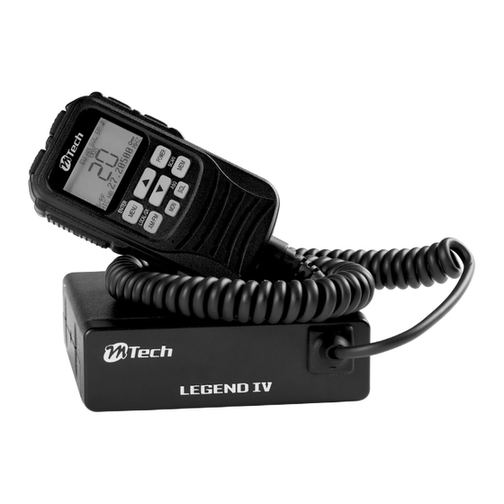
This document is the operating guide for the CB Transceiver LEGEND IV. Included in your package If any of these items are missing or damaged, immediately contact your place of purchase. LEGEND IV CB radio Microphone and hook Cable Mounting bracket, mic hanger, knobs, and mounting hardware NOTES! NOTES! You must use a CB antenna (sold separately) with this radio. -
Page 5: Features
Features Function LCD Display • AM/FM Mode select • Memory (Memory Channel) • Emergency CH9 / CH19 Mode • All Channel Scan • Memory Channel Scan • Roger Beep • Key Beep • Key Lock • TOT (Trasmit Time Out Timer) •... -
Page 6: Controls And Rear Panel
Controls and Rear Panel Controls *These drawings are just for reference, and do not reflect the final product. 1. Power 2. Volume 3. Squelch 4. Display 5. Channel selector 6. AM/FM and LO/DX MEM and SCAN 8. LOCK 10. CH 9 / 19 11. -
Page 7: Installation
Installation Where and how to mount your mobile CB radio You should choose the most appropriate setting from a simple • and practical point of view. Your CB radio should not interfere with the driver or the passengers. • Remember to provide for the passing and protection of different •... -
Page 8: Antenna Installation
4.1 Antenna installation a. Choosing your antenna • For CB radios, the longer and matched antenna is the better results. b. Mobile antenna • Must be fixed to the vehicle where there is a maximum of metallic surface (ground plane), away from windscreen mountings. •... -
Page 9: Power Installation
4.2 Power installation a. Choosing your antenna Your LEGEND IV is protected against an inversion of polarities. Your equipment must be supplied with a continued current of DC.12V Ⓐ . 1. Check that the battery is of 12 volts. 2. Locate the positive and negative terminals of the battery ⊕ is red and ⊖... -
Page 10: Operation
Operation * Drawing is just for reference. LCD Display Layout A. Memory Channel G. Roger Beep M. High Cut B. Configuration H. R.F Gain N. Signal Bar/Power C. Channel I. CTCSS/DCS code O. Emergency Channel D. Mode J. Key Lock P. -
Page 11: S/Rf Meter
* Drawing is just for reference. Element of LCD Contents of the Indicator 5.4 S/RF Meter SRF meter indicate the receiving signal strength in RX mode. The SRF meter is used as RF power indicator in TX mode. SRF meter indicators are 7 steps from 1 (weak) to 7 (strong) 5.5 Channel Select Push or push and hold up/down keys. -
Page 12: Mem/Scan
* Drawing is just for reference. Element of LCD Contents of the Indicator 5.8 MEM/SCAN a) MEM (short push) Those function are memorized when memory command is done : Mode AM/FM , Channel number and CTCSS or DCS. MEM Store (8 memories) 1. -
Page 13: Micro Plug Rj45
* Drawing is just for reference. Element of LCD Contents of the Indicator 5.11 Micro Plug RJ45 The plug is located on the front panel of the transceiver and makes the setting of the equipment into the dashboard easier. Push 1, pull 2 to remove 5.12 TRANSMISSION a) PTT Press to transmit a message, TX is displayed and... - Page 14 * Drawing is just for reference. Element of LCD Contents of the Indicator Memory Scan Push the MENU key to select MEMO SCAN setting. Current setting is displayed. Push up/down keys to select the On or Off. Vox Sensitivity Level The VOX Sensitivity Level allows the adjustment of the microphone for an optimum transmission quality.
- Page 15 * Drawing is just for reference. Element of LCD Contents of the Indicator Speaker Select the receiving audio speaker. Push the MENU key to select Audio path setting. Current setting is displayed. Push up/down keys to select the main speaker or MIC speaker or both main and MIC speaker.
-
Page 16: Confi Guration (Confi Guration: Eu;Pl;D,Ec;Uk)
* Drawing is just for reference. Element of LCD Contents of the Indicator LCD Contrast The Contrast function changes the contrast (from 1 to 10) the characters. Push the MENU key to select Contrast setting. Current setting is displayed. Push up/down keys to select the contrast. -
Page 17: Specifi Cations
№ MENU Item Effective Selectable Item Default BACK LIGHT GREEN CYAN BLUE RED GREEN COLOUR PINK DIMMER OFF 1 to 9 LCD CONTRAST 1 to 10 b. ENTER (long push 2 seconds) Push and hold ENTER (MENU) key or push PTT key to complete the setting and exit the MENU mode. -
Page 18: Glossary
Glossary Technical Vocabulary Amplitude Modulation Citizen's Band Channel Continuous Wave Long Distance Liaison Dual Watch Frequency Modulation Greenwich Meantime High Frequency Low Frequency Lower Side Band Receiver Single Side Band Standing Wave Ratio Short Wave Listening Short Wave Transmitter Ultra High Frequency Upper Side Band Very High Frequency NORMS... -
Page 19: Frequency List
Frequency List 8.1 CONFIG 1 Frequency List (EU Confi guration) CONFIG 1 / EUROPE 40 CH FM (4W), 40 CH AM (4W) CH № Frequency (MHz) AM RX AM TX FM RX FM TX ⃝ ⃝ 4W ⃝ ⃝ 4W 26.965 ⃝... -
Page 20: Confi G2 Frequency List (Pl Confi Guration)
8.2 CONFIG 2 Frequency List (PL Confi guration) CONFIG 2 / POLAND -5KHz 40 CH FM (4W), 40 CH AM (4W) CH № Frequency (MHz) AM RX AM TX FM RX FM TX ⃝ ⃝ 4W ⃝ ⃝ 4W 26.960 ⃝... -
Page 21: Confi G3 Frequency List (D Confi Guration)
8.3 CONFIG 3 Frequency List (D Confi guration) CONFIG 3 / GERMANY 80 CH FM (4W), 40 CH AM (4W) CH № Frequency (MHz) AM RX AM TX FM RX FM TX ⃝ ⃝ 4W ⃝ ⃝ 4W 26.965 ⃝ ⃝... - Page 22 CONFIG 3 / GERMANY 80 CH FM (4W), 40 CH AM (4W) CH № Frequency (MHz) AM RX AM TX FM RX FM TX ✕ ✕ ⃝ ⃝ 4W 26.565 ✕ ✕ ⃝ ⃝ 4W 26.575 ✕ ✕ ⃝ ⃝ 4W 26.585 ✕...
-
Page 23: Confi G4 Frequency List (Ec Confi Guration)
8.4 CONFIG 4 Frequency List (EC Confi guration) CONFIG 4 / CEPT 40 CH FM (4W) CH № Frequency (MHz) AM RX AM TX FM RX FM TX ✕ ✕ ⃝ ⃝ 4W 26.965 ✕ ✕ ⃝ ⃝ 4W 26.975 ✕... -
Page 24: Confi G5 Frequency List (Uk Confi Guration)
8.5 CONFIG 5 Frequency List (UK Confi guration) CEPT FREQUENCY MODE CONFIG 5 / EC 40 CH FM (4W) CH № Frequency (MHz) AM RX AM TX FM RX FM TX ✕ ✕ ⃝ ⃝ 4W 26.965 ✕ ✕ ⃝ ⃝... - Page 25 ENGLAND FREQUENCY MODE CONFIG 5 / EN 40 CH FM (4W) CH № Frequency (MHz) AM RX AM TX FM RX FM TX ✕ ✕ ⃝ ⃝ 4W 27.60125 ✕ ✕ ⃝ ⃝ 4W 27.61125 ✕ ✕ ⃝ ⃝ 4W 27.62125 ✕...
-
Page 26: Tones
Tones CTCSS Tons List № Frequency (Hz) № Frequency (Hz) № Frequency (Hz) 103.5 162.2 67.0 107.2 167.9 71.9 110.9 173.8 74.4 114.8 179.9 77.0 118.8 186.2 79.7 123.0 192.8 82.5 127.3 203.5 85.4 131.8 210.7 88.5 136.5 218.1 91.5 141.3 225.7 94.8... -
Page 27: Declaration Of Conformity
Declaration of Conformity I here by declare that the product LEGEND IV, CB Radio satisfi es all the technical regulations applicable to the product within the scope of Radio Equipment and Telecommunications Terminal Equipment (R&TTE) Directive 1999/5/EC: ETSI EN 300 135-2 (V1.2.1, 2008-2), ETSI EN 300 433-2 (V1.3.1, 2011-07) ETSI EN 301 489-13 (V1.2.1, 2002-8), ETSI EN 301 489-1 (V1.9.2, 2011-09) - Page 28 This user manual is subject to change according to M-Tech Dynamic Corporation Limited without notice. Printed in China...
Need help?
Do you have a question about the Legend IV and is the answer not in the manual?
Questions and answers